EP4503084A1 - Mécanisme de fonctionnement bidirectionnel pour dispositif de commutation et ensemble de dispositif de commutation - Google Patents
Mécanisme de fonctionnement bidirectionnel pour dispositif de commutation et ensemble de dispositif de commutation Download PDFInfo
- Publication number
- EP4503084A1 EP4503084A1 EP23210567.6A EP23210567A EP4503084A1 EP 4503084 A1 EP4503084 A1 EP 4503084A1 EP 23210567 A EP23210567 A EP 23210567A EP 4503084 A1 EP4503084 A1 EP 4503084A1
- Authority
- EP
- European Patent Office
- Prior art keywords
- driving member
- driving
- operation handle
- switching device
- rotate
- Prior art date
- Legal status (The legal status is an assumption and is not a legal conclusion. Google has not performed a legal analysis and makes no representation as to the accuracy of the status listed.)
- Pending
Links
Images




Classifications
-
- H—ELECTRICITY
- H01—ELECTRIC ELEMENTS
- H01H—ELECTRIC SWITCHES; RELAYS; SELECTORS; EMERGENCY PROTECTIVE DEVICES
- H01H71/00—Details of the protective switches or relays covered by groups H01H73/00 - H01H83/00
- H01H71/10—Operating or release mechanisms
- H01H71/50—Manual reset mechanisms which may be also used for manual release
- H01H71/56—Manual reset mechanisms which may be also used for manual release actuated by rotatable knob or wheel
-
- H—ELECTRICITY
- H01—ELECTRIC ELEMENTS
- H01H—ELECTRIC SWITCHES; RELAYS; SELECTORS; EMERGENCY PROTECTIVE DEVICES
- H01H21/00—Switches operated by an operating part in the form of a pivotable member acted upon directly by a solid body, e.g. by a hand
- H01H21/02—Details
- H01H21/18—Movable parts; Contacts mounted thereon
- H01H21/22—Operating parts, e.g. handle
-
- H—ELECTRICITY
- H01—ELECTRIC ELEMENTS
- H01H—ELECTRIC SWITCHES; RELAYS; SELECTORS; EMERGENCY PROTECTIVE DEVICES
- H01H3/00—Mechanisms for operating contacts
- H01H3/02—Operating parts, i.e. for operating driving mechanism by a mechanical force external to the switch
-
- H—ELECTRICITY
- H01—ELECTRIC ELEMENTS
- H01H—ELECTRIC SWITCHES; RELAYS; SELECTORS; EMERGENCY PROTECTIVE DEVICES
- H01H21/00—Switches operated by an operating part in the form of a pivotable member acted upon directly by a solid body, e.g. by a hand
- H01H21/02—Details
- H01H21/04—Cases; Covers
-
- H—ELECTRICITY
- H01—ELECTRIC ELEMENTS
- H01H—ELECTRIC SWITCHES; RELAYS; SELECTORS; EMERGENCY PROTECTIVE DEVICES
- H01H21/00—Switches operated by an operating part in the form of a pivotable member acted upon directly by a solid body, e.g. by a hand
- H01H21/02—Details
- H01H21/18—Movable parts; Contacts mounted thereon
- H01H21/36—Driving mechanisms
-
- H—ELECTRICITY
- H01—ELECTRIC ELEMENTS
- H01H—ELECTRIC SWITCHES; RELAYS; SELECTORS; EMERGENCY PROTECTIVE DEVICES
- H01H3/00—Mechanisms for operating contacts
- H01H3/32—Driving mechanisms, i.e. for transmitting driving force to the contacts
-
- H—ELECTRICITY
- H01—ELECTRIC ELEMENTS
- H01H—ELECTRIC SWITCHES; RELAYS; SELECTORS; EMERGENCY PROTECTIVE DEVICES
- H01H31/00—Air-break switches for high tension without arc-extinguishing or arc-preventing means
- H01H31/02—Details
-
- H—ELECTRICITY
- H01—ELECTRIC ELEMENTS
- H01H—ELECTRIC SWITCHES; RELAYS; SELECTORS; EMERGENCY PROTECTIVE DEVICES
- H01H71/00—Details of the protective switches or relays covered by groups H01H73/00 - H01H83/00
- H01H71/10—Operating or release mechanisms
-
- H—ELECTRICITY
- H01—ELECTRIC ELEMENTS
- H01H—ELECTRIC SWITCHES; RELAYS; SELECTORS; EMERGENCY PROTECTIVE DEVICES
- H01H71/00—Details of the protective switches or relays covered by groups H01H73/00 - H01H83/00
- H01H71/10—Operating or release mechanisms
- H01H71/50—Manual reset mechanisms which may be also used for manual release
- H01H71/56—Manual reset mechanisms which may be also used for manual release actuated by rotatable knob or wheel
- H01H2071/565—Manual reset mechanisms which may be also used for manual release actuated by rotatable knob or wheel using a add on unit, e.g. a separate rotary actuator unit, mounted on lever actuated circuit breakers
Definitions
- the present disclosure relates to a bidirectional operation mechanism for a switching device and a switching device assembly.
- the external handle drives the closing operation and the opening operation of the internal contact system, and the handle also has the function of state indication.
- a small number of automatic operation mechanisms can be realized by adding the function of driving module, but this driving mode generally directly drive the handle, and the indication function of opening and closing needs an additional device to realize.
- the bidirectional operation mechanism is installed to the switching device and includes: a housing; an operation handle, rotatably installed to the housing, capable of rotating between a closed position and an open position, and indicating the closed position and the open position; a first driving member, rotatably installed to the housing, fixedly connected to the operation handle and capable of rotating together with the operation handle; a second driving member, rotatably installed to the housing, operatively connected to the first driving member on one hand, and operatively connected to the switching device on the other hand, upon an external force acting on the operation handle to drive the operation handle rotate between the closed position and the open position, the operation handle drives the first driving member to rotate together, so that the first driving member abuts against and drives the second driving member to rotate, thereby enabling the switching device to perform a closing operation and an opening operation, upon the switching device performing the closing operation and the opening operation under an action of a driving force of the switching device itself, the switching
- a transmission member pivotally arranged on the second driving member and capable of pivoting between an abutting position and a disengaged position
- a trigger member pivotally arranged on the second driving member and capable of pivoting between a locked position and an unlocked position under an action of an electromagnet associated with the trigger member, in the locked position of the trigger member, the trigger member is located on a pivoting path of the transmission member along the first direction, is able to abut against the transmission member in the abutting position and prevent the transmission member from pivoting in the first direction, upon the transmission member being in the disengaged position, the trigger member does not abut against the transmission member, the first direction corresponds to a rotating direction of the operation handle from the closed position to the open position, in the unlocked position of the trigger member, the trigger member is not located on the pivoting path of the transmission member along the first direction and does not abut against the transmission member.
- the trigger member in the closed position, abuts against the transmission member, and upon an external force acting on the operation handle to drive the operation handle to rotate from the closed position to the open position, the transmission member pivots from the abutting position to the disengaged position, and a driving force of the first driving member is not transmitted to the second driving member;
- the first driving member includes a protrusion extending toward the second driving member
- the second driving member includes a groove
- the protrusion of the first driving member extends into the groove
- the protrusion is configured to abut against the transmission member
- the first driving member rotates in the first direction, causing the transmission member to pivot from the abutting position to the disengaged position without abutting against the trigger member, after the first driving member rotating by a predetermined angle, the protrusion of the first driving member abuts against one end of the groove and pushes the second driving member to rotate in the first direction, so that the switching device performs the opening operation.
- the trigger member includes a first mating feature and the transmission member includes a second mating feature, in the locked position of the trigger member, upon the transmission member pivoting in the first direction, the second mating feature of the transmission member will abut against the first mating feature of the trigger member, thus being blocked by the trigger member.
- the first mating feature and the second mating feature are in the form of hooks.
- the first driving member rotates in a second direction, causing the protrusion of the first driving member to push the transmission member from the disengaged position to the abutting position, and after the first driving member rotating for a predetermined angle, the transmission member pivots to the abutting position to abut against the trigger member, and then the first driving member continues to rotate in the second direction to drive the second driving member to together rotate in the second direction through the transmission member and the trigger member, so that the switching device performs the closing operation.
- the second driving member rotates in the first direction, at this time, the trigger member is in the locked position and the transmission member is in the abutting position, so that the trigger member and the transmission member abut against each other, so that a driving force of the second driving member is transmitted to the first driving member, so that the first driving member also rotates in the first direction, thereby driving the operation handle to rotate from the closing position to the open position.
- one end of the operation handle spring is operatively connected to the operation handle, and the other end of the operation handle spring is fixed to the housing, and is configured such that, in a case that the operation handle is driven by the second driving member to rotate from the closed position to the open position, upon the second driving member rotating in place, the operation handle spring passes through a dead point position, the first driving member continues to rotate in the first direction, so that the protrusion pushes the transmission member to pivot in the second direction from the abutting position to the disengaged position, and disengage from abutment with the trigger member.
- the second driving member rotates in the second direction, at this time, the trigger member is in the locked position and the transmission member is in the disengaged position, one end of the groove of the second driving member abuts against the protrusion of the first driving member, and a rotation of the second driving member pushes the first driving member to rotate in the second direction, so that the operation handle rotates from the open position to the closed position.
- the operation handle spring passes through the dead point position, the first driving member continues to rotate in the second direction, so that the protrusion pushes the transmission member to pivot in the first direction from the disengaged position to the abutting position, and abuts against the trigger member in the locked position.
- the transmission member includes a pivoting part and a first leg and a second leg extending from the pivoting part, and the protrusion of the first driving member extends between the first leg and the second leg and abuts against the first leg and the second leg.
- the transmission member includes a pivoting part and a single leg extending from the pivoting part, and one end of a torsion spring is fixedly connected to the pivoting part of the transmission member and the other end of the torsion spring is fixedly connected to the second driving member, and the torsion spring is configured to keep the protrusion of the transmission member and the first driving member in contact all the time,
- the electromagnet associated with the trigger member is configured to receive an electrical signal of the switching device for tripping operation, so as to drive the trigger member to pivot from the locked position to the unlocked position, and then the second driving member rotates in the first direction, upon the operation handle being blocked and being not able to rotate, the transmission member is pushed by the protrusion of the first driving member to rotate in the first direction, and the protrusion of the first driving member relatively moves in the groove of the second driving element.
- the return spring stores energy along with a rotation of the second driving member in the first direction, after the second driving member rotates in place, in a case that the operation handle is released, the first driving member and the operation handle rotate together in the first direction under an action of the return spring.
- a first sensor arranged at a side of the first driving member and is configured that, in the closed position of the operation handle, the first driving element excites the first sensor, and the first sensor is communicatively connected to an electronic switch of the switching device, and upon the operation handle driving the first driving member to leave the closed position, the first driving member deactivates the first sensor, so that the first sensor sends an opening warning signal to the electronic switch.
- a second sensor arranged at another side of the first driving member opposite to the side, and is configured that, in the open position of the operation handle, the first driving member excites the second sensor, and the second sensor is communicatively connected to the electronic switch of the switching device, and upon the operation handle driving the first driving member to rotate from the open position to the closed position, the first driving member deactivates the second sensor, so that the second sensor sends a closing warning signal to the electronic switch.
- the first sensor and the second sensor are selected from microswitches, hall sensors and grating sensors.
- the present disclosure also provides a switching device assembly, the switching device assembly includes a switching device and the bidirectional operation mechanism as described above, the bidirectional operation mechanism is installed to the switching device.
- the feasible embodiments within the protection scope of this disclosure may have fewer components, other components not shown in the accompanying drawings, different components, components arranged differently or components connected differently, etc.
- two or more components in the drawings may be implemented in a single component, or a single component shown in the drawings may be implemented as a plurality of separate components.
- the bidirectional operation mechanism of the present disclosure can be installed on a switching device, which includes but not limited to a circuit breaker, a contactor, a solid-state circuit breaker and a disconnector.
- the bidirectional operation mechanism is configured to be able to operate in both a forward direction and a reverse direction.
- the operation handle is manually operated to cause the switching device to open and close.
- the bidirectional operation mechanism being operated in the reverse direction, that is, upon the switching device itself being electrically operated to open and close, the opening operation and the closing operation of the switching device can cause the operation handle to rotate, thus indicating the opening and closing.
- the bidirectional operation mechanism includes a housing 1, an operation handle 2, a first driving member 3 and a fourth driving member 4, which are all rotatably installed to the housing 1.
- the bidirectional operation mechanism also includes a transmission member 5 and a trigger member 6.
- the operation handle 2 is fixedly connected to the first driving member 3, so that both of them can rotate at the same time.
- the operation handle 2 drives the first driving member 3 to rotate, and the first driving member 3 is able to drive the second driving member 4 to rotate through the transmission member 5 and the trigger member 6.
- the opening operation or the closing operation of the switching device drives the second driving member 4 to rotate, and the second driving member 4 is able to drive the first driving member 3 to rotate through the transmission member 5 and the trigger member 6.
- a transmission member 5 of an embodiment is shown, and Fig. 14 shows a transmission member 5' of another embodiment.
- the structures of the two transmission members are different, the functions that the two transmission members of the two embodiments can achieve are exactly the same.
- the transmission member is capable of pivoting between an abutting position and a disengaged position, and the trigger member is capable of rotating between a locked position and an unlocked position.
- the transmission member In the abutting position, the transmission member abuts against the trigger member in the locked position; in the disengaged position, the transmission member disengages from the trigger member in the locked position, and in the unlocked position of the trigger member, the transmission member does not abut against the trigger member.
- the trigger member is in the locked position, and only upon the switching device being tripped, the trigger member pivots to the unlocked position.
- the trigger member In the locked position of the trigger member, the trigger member is located on a pivot path of the transmission member along the first direction ( a rotating direction from the closed position to the open position), and is able to abut against the transmission member in the abutting position and prevent the transmission member from pivoting in the first direction, and the trigger member is not located on the pivot path of the transmission member along the first direction and does not abut against the transmission member.
- both the transmission member and the trigger member can transmit a driving force between the first driving member and the second driving member.
- a driving force of the switching device e.g., electric drive, realized by electromagnetic coil, etc.
- the transmission member 5 is shown to include a pivoting part 51, a first leg 52 and a second leg 53 which extend from the pivoting part.
- the first driving member 3 includes a protrusion 31 extending toward the second driving member 4, the protrusion 31 extends between and abuts against the first leg 52 and the second leg 53, and the second driving member 4 includes a groove 41, and the protrusion 31 also extends into the groove 41.
- the trigger member 6 has a first mating feature 61
- the transmission member 5 has a second mating feature 54
- the second mating feature 54 of the transmission member is able to abut against the first mating feature 61 of the trigger member.
- the first mating feature and the second mating feature are in the form of hooks, but it should be understood by those skilled in the art that there are other mating features as long as the trigger member and the transmission member can be abutted.
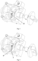
- Fig. 1 shows that the operation handle is in the closed position.
- the transmission member 5 is in the abutting position
- the trigger member 6 is in the locked position
- the transmission member 5 abuts against the trigger member 6.
- the first driving member 3 Upon an external force acting on the operation handle to drive the operation handle to rotate in the first direction (i.e. a counterclockwise direction) from the closed position to the open position, the first driving member 3 also rotates in the first direction, so that the transmission member pivots from the abutting position to the disengaged position without abutting against the trigger member.
- the first driving member 3 rotates in the first direction, so that the protrusion 31 pushes the first leg 52, and the transmission member 5 pivots to the disengaged position in a second direction (i.e., a clockwise direction) opposite to the first direction, so as to disengage from the abutment with the trigger member 6.
- a second direction i.e., a clockwise direction
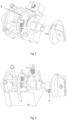
- the protrusion 31 of the first driving member abuts against one end of the groove, as illustrated by Fig. 2 , and pushes the second driving member 4 to rotate in the first direction, and finally reaches the position shown in Fig. 3 , so that the switching device performs the opening operation.
- the first driving member 3 rotates in the second direction, so that the protrusion of the first driving member pushes the transmission member from the disengaged position to the abutting position.
- the first driving member 3 rotates in the second direction, so that the protrusion 31 pushes the second leg 53, and the transmission member pivots in the first direction, and reaches the position shown in Fig. 4 .
- the transmission member 5 abuts against the trigger member 6 and is blocked by the trigger member.
- the continued rotation of the first driving member 3 in the second direction drives the second driving member to rotate together in the second direction through the transmission member and the trigger member, so that the switching device performs the closing operation.
- the second driving member 4 rotates in the first direction.
- the trigger member is in the locked position and the transmission member is in the abutting position, so that the trigger member and the transmission member abut against each other, a driving force of the second driving member 4 is transmitted to the first driving member 3, so that the first driving member 3 also rotates in the first direction, thereby driving the operation handle to rotate from the closed position to the open position, and reach the position shown in Figs. 5 and 6 .
- the second driving member 4 has been rotated in place, but the first driving member 3 and the operation handle 2 have not been rotated in place.
- an operation handle spring 7 is fixedly connected to the operation handle 1, and the other end of the operation handle spring 7 is fixed to the housing 2.
- the operation handle spring 7 is configured that upon the second driving member 4 rotating in place, the operation handle spring passes through the dead point position, the first driving member continues to rotate in the first direction, so that the protrusion pushes the second leg 53 of the transmission member 5 to pivot in the second direction from the abutting position to the disengaged position, disengage from the abutment with the trigger member, and finally reach the open position shown in Fig. 3 .
- the second driving member 4 rotates in the second direction.
- the trigger member is in the locked position and the transmission member is in the disengaged position
- one end of the groove 41 of the second driving member abuts against the protrusion 31 of the first driving member, and the rotation of the second driving member pushes the first driving member to rotate in the second direction, so that the operation handle rotates from the open position to the closed position, and reaches the position shown in Figs. 7 and 8 .
- the second driving member has been rotated in place, however, the first driving member and the operation handle have not been rotated in place.
- the operation handle spring passes through the dead point position, the first driving member 3 continues to rotate in the second direction, so that the protrusion pushes the transmission member to pivot from the disengaged position to the abutting position in the first direction, and abut against the trigger member in the locked position.
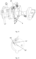
- Fig. 9 shows that, during s tripping period, the switching device is tripped under the action of a tripper of the switching device itself.
- the electromagnet 62 associated with the trigger member 6 is configured to receive an electrical signal of tripping operation of the switching device, press the trigger member 6 through a pressing member 63, so that the trigger member 6 pivots from the locked position to the unlocked position.
- the operation handle cannot rotate due to accidents, then, the tripping operation of the switching device drives the second driving member 4 to rotate in the first direction, causing the protrusion to push the second leg 53 of the transmission member 5, so that the transmission member rotates in the first direction, and the protrusion of the first driving member relatively moves in the groove of the second driving member, thus reaching the position as illustrated by Fig. 10 .
- the trigger member 6 can return to the locked position under the action of a return spring 63.
- One end of the return spring 63 is fixedly connected to the second driving member, and the other end of the return spring 63 is fixedly connected to the trigger member.
- a return spring 7 is also arranged between the first driving member 3 and the second driving member 4, upon the switching device performing a tripping operation, if the blocking of the operation handle disappears after reaching the position as shown in Fig. 10 , the first driving member and the operation handle can rotate together in the first direction under the action of the return spring 7.
- the bidirectional operation mechanism may also include a first sensor 8, which is arranged at a side of the first driving member and configured that, in the closed position of the operation handle, the first driving member excites the first sensor.
- the first sensor is communicatively connected to an electronic switch of the switching device, and upon the operation handle driving the first driving member to leave the closed position, the first driving member deactivates the first sensor, so that the first sensor sends an opening warning signal to the electronic switch.
- the bidirectional operation mechanism also includes a second sensor 9, which is arranged on the other side of the first driving member opposite to the side, and is configured that, in the open position of the operation handle, the first driving member excites the second sensor, the second sensor is communicatively connected to the electronic switch of the switching device, and upon the operation handle driving the first driving member to rotate from the open position to the closed position, the first driving member deactivates the second sensor, so that the second sensor sends a closing warning signal to the electronic switch.
- a second sensor 9 which is arranged on the other side of the first driving member opposite to the side, and is configured that, in the open position of the operation handle, the first driving member excites the second sensor, the second sensor is communicatively connected to the electronic switch of the switching device, and upon the operation handle driving the first driving member to rotate from the open position to the closed position, the first driving member deactivates the second sensor, so that the second sensor sends a closing warning signal to the electronic switch.
- the first sensor and the second sensor may be provided.
- the sensor can be in the form of a microswitch, as illustrated by the accompanying drawings, but the sensor can also be a hall sensor, a grating sensor and other forms.
- the configuration of the first sensor and the second sensor is particularly beneficial upon the switching device is a solid-state circuit breaker.
- Fig. 14 shows a transmission member 5' of another embodiment, the transmission member 5'includes a pivoting part 51' and a single leg 52'.
- One end of a torsion spring 53' is fixedly installed to the pivoting part 51' and the other end of the torsion spring 53' is fixedly installed to the second driving member 4.
- the torsion spring 53' is configured to keep the transmission member 5' in contact with the protrusion of the first driving member all the time, that is, the torsion spring 53' applies a force to drive the transmission member 5' to rotate toward the protrusion of to make the transmission member, after the protrusion of the first driving member rotates, the force of the torsion spring 53' drive the protrusion to rotate, so as to keep the contact between the transmission member and the protrusion.
- the transmission member 5' of this embodiment has the same function as the above-mentioned transmission member 5, and only the transmission member 5' during operation will be briefly described below.
- the protrusion 31 of the first driving member abuts against the single leg 52', so as to keep the transmission member 5' in the abutting position and abutting against the trigger member in the locked position.
- the protrusion 31 disengages from the abutment with the single leg 52', so that the transmission member 5' pivots to the disengaged position under the action of the torsion spring 53'.
- the protrusion Upon manually moving from the open position to the closed position, the protrusion abuts against the single leg 52' to make the transmission member overcome the elastic force of the torsion spring 53', pivot to the abutting position, and abut against the trigger member in the locked position.
- the single leg 52' Upon being electrically driven to move from the closed position to the open position, the single leg 52' abuts against the protrusion 31 and pushes the first driving member to rotate, after the operation handle spring passes through the dead point position, the protrusion continues to rotate, so that the transmission member pivots from the abutting position to the disengaged position under the action of the torsion spring 53'.
- one end of the groove of the second driving member abuts against the protrusion and pushes the protrusion, after the operation handle spring passes through the dead point position, the protrusion pushes the single leg 52' to overcome the elastic force of the torsion spring 53' and drive the transmission member to pivot to the abutting position.
- the present disclosure also provides a switching device assembly, which comprises the bidirectional operation mechanism and the switching device 10.
- the switching device can be any form of switch.
- the second driving member of the bidirectional operation mechanism is connected to the switching device by any suitable transmission mechanism, so that the switching device can perform opening operation and closing operation.
- suitable transmission mechanism those skilled in the art can design it according to their needs, and it is not the focus of the present disclosure, so it will not be described here.
- the second driving member can be driven by the first driving member to realize the opening operation and closing operation of the switching device, and the first driving member can also be driven by the second driving member to realize accurately indication of the opening position and the closed position by the operation handle, and during this process, the functions of pre-triggering alarm and free tripping can be realized.
Landscapes
- Driving Mechanisms And Operating Circuits Of Arc-Extinguishing High-Tension Switches (AREA)
- Mechanisms For Operating Contacts (AREA)
Applications Claiming Priority (1)
| Application Number | Priority Date | Filing Date | Title |
|---|---|---|---|
| CN202310953065.7A CN119446806A (zh) | 2023-07-31 | 2023-07-31 | 用于开关设备的双向操作机构及开关设备组件 |
Publications (1)
| Publication Number | Publication Date |
|---|---|
| EP4503084A1 true EP4503084A1 (fr) | 2025-02-05 |
Family
ID=88839537
Family Applications (1)
| Application Number | Title | Priority Date | Filing Date |
|---|---|---|---|
| EP23210567.6A Pending EP4503084A1 (fr) | 2023-07-31 | 2023-11-17 | Mécanisme de fonctionnement bidirectionnel pour dispositif de commutation et ensemble de dispositif de commutation |
Country Status (3)
| Country | Link |
|---|---|
| US (1) | US20250046545A1 (fr) |
| EP (1) | EP4503084A1 (fr) |
| CN (1) | CN119446806A (fr) |
Cited By (1)
| Publication number | Priority date | Publication date | Assignee | Title |
|---|---|---|---|---|
| EP4664500A1 (fr) * | 2024-04-15 | 2025-12-17 | Schneider Electric Industries SAS | Mécanisme de fonctionnement pour dispositif de commutation et ensemble de dispositif de commutation |
Citations (3)
| Publication number | Priority date | Publication date | Assignee | Title |
|---|---|---|---|---|
| DE4312428C1 (de) * | 1993-04-19 | 1994-11-03 | Kloeckner Moeller Gmbh | Handbetätigungsvorrichtung für gekapselte elektrische Schaltgeräte |
| GB2279810A (en) * | 1993-07-03 | 1995-01-11 | Kloeckner Moeller Gmbh | A lockable rotary drive for a circuit breaker |
| US20230154702A1 (en) * | 2020-07-20 | 2023-05-18 | Huawei Digital Power Technologies Co., Ltd. | Rotary switch |
-
2023
- 2023-07-31 CN CN202310953065.7A patent/CN119446806A/zh active Pending
- 2023-11-17 EP EP23210567.6A patent/EP4503084A1/fr active Pending
- 2023-11-21 US US18/515,431 patent/US20250046545A1/en active Pending
Patent Citations (3)
| Publication number | Priority date | Publication date | Assignee | Title |
|---|---|---|---|---|
| DE4312428C1 (de) * | 1993-04-19 | 1994-11-03 | Kloeckner Moeller Gmbh | Handbetätigungsvorrichtung für gekapselte elektrische Schaltgeräte |
| GB2279810A (en) * | 1993-07-03 | 1995-01-11 | Kloeckner Moeller Gmbh | A lockable rotary drive for a circuit breaker |
| US20230154702A1 (en) * | 2020-07-20 | 2023-05-18 | Huawei Digital Power Technologies Co., Ltd. | Rotary switch |
Cited By (1)
| Publication number | Priority date | Publication date | Assignee | Title |
|---|---|---|---|---|
| EP4664500A1 (fr) * | 2024-04-15 | 2025-12-17 | Schneider Electric Industries SAS | Mécanisme de fonctionnement pour dispositif de commutation et ensemble de dispositif de commutation |
Also Published As
| Publication number | Publication date |
|---|---|
| CN119446806A (zh) | 2025-02-14 |
| US20250046545A1 (en) | 2025-02-06 |
Similar Documents
| Publication | Publication Date | Title |
|---|---|---|
| CN207966888U (zh) | 一种漏电断路器 | |
| JPH0210622A (ja) | 補助トリップ装置 | |
| EP0546166A1 (fr) | Coupe-circuit a telecommande | |
| CN107424879B (zh) | 一种剩余电流脱扣机构及断路器 | |
| US5982258A (en) | Tripping device for a circuit breaker equipped with an electrical fault indication | |
| EP4503084A1 (fr) | Mécanisme de fonctionnement bidirectionnel pour dispositif de commutation et ensemble de dispositif de commutation | |
| CN111681930A (zh) | 断路器 | |
| CN112967910A (zh) | 断路器的操作机构 | |
| CN104508788A (zh) | 用于保护线路的电气装置的辅助致动装置 | |
| KR970004581B1 (ko) | 제어모듀울 및/또는 신호모듀울에 결합가능한 보호장치 | |
| CN118448224A (zh) | 一种塑壳断路器的磁通脱扣器复位结构 | |
| CA2783232C (fr) | Dispositif de commutation electrique et mecanisme connexe de declenchement secondaire | |
| EP1487002A2 (fr) | Dispositif électrique d'actionnement à distance | |
| EP3292558B1 (fr) | Appareil de commutation électrique et ensemble déclencheur associé | |
| CN219106038U (zh) | 一种操作机构和断路器 | |
| CN206774474U (zh) | 一种剩余电流脱扣机构及断路器 | |
| CN109545630B (zh) | 一种断路器附件的操作机构、断路器附件及组合式断路器 | |
| CN221766578U (zh) | 用于开关设备的操作机构及开关设备组件 | |
| CN223140697U (zh) | 一种分励脱扣器及其与断路器的拼接结构 | |
| US20250323000A1 (en) | Operation mechanism for switching device and switching device assembly | |
| US3070682A (en) | Automatic trip indicator and lockout for circuit breakers | |
| CN210608965U (zh) | 电动机起动器 | |
| US20260081088A1 (en) | Remote control breakers | |
| EP4495968A1 (fr) | Module de verrouillage pour dispositif électrique et contacteur comprenant le module de verrouillage | |
| CN222530259U (zh) | 断路器二合一机械连锁装置及开关柜 |
Legal Events
| Date | Code | Title | Description |
|---|---|---|---|
| PUAI | Public reference made under article 153(3) epc to a published international application that has entered the european phase |
Free format text: ORIGINAL CODE: 0009012 |
|
| STAA | Information on the status of an ep patent application or granted ep patent |
Free format text: STATUS: THE APPLICATION HAS BEEN PUBLISHED |
|
| AK | Designated contracting states |
Kind code of ref document: A1 Designated state(s): AL AT BE BG CH CY CZ DE DK EE ES FI FR GB GR HR HU IE IS IT LI LT LU LV MC ME MK MT NL NO PL PT RO RS SE SI SK SM TR |
|
| STAA | Information on the status of an ep patent application or granted ep patent |
Free format text: STATUS: REQUEST FOR EXAMINATION WAS MADE |
|
| 17P | Request for examination filed |
Effective date: 20250714 |