EP4503089A1 - Dispositif d'analyse - Google Patents
Dispositif d'analyse Download PDFInfo
- Publication number
- EP4503089A1 EP4503089A1 EP22933891.8A EP22933891A EP4503089A1 EP 4503089 A1 EP4503089 A1 EP 4503089A1 EP 22933891 A EP22933891 A EP 22933891A EP 4503089 A1 EP4503089 A1 EP 4503089A1
- Authority
- EP
- European Patent Office
- Prior art keywords
- pore
- vacuum
- sealing plug
- vacuum pump
- plug
- Prior art date
- Legal status (The legal status is an assumption and is not a legal conclusion. Google has not performed a legal analysis and makes no representation as to the accuracy of the status listed.)
- Pending
Links
Images


Classifications
-
- H—ELECTRICITY
- H01—ELECTRIC ELEMENTS
- H01J—ELECTRIC DISCHARGE TUBES OR DISCHARGE LAMPS
- H01J37/00—Discharge tubes with provision for introducing objects or material to be exposed to the discharge, e.g. for the purpose of examination or processing thereof
- H01J37/02—Details
- H01J37/18—Vacuum locks ; Means for obtaining or maintaining the desired pressure within the vessel
-
- H—ELECTRICITY
- H01—ELECTRIC ELEMENTS
- H01J—ELECTRIC DISCHARGE TUBES OR DISCHARGE LAMPS
- H01J49/00—Particle spectrometers or separator tubes
- H01J49/02—Details
- H01J49/04—Arrangements for introducing or extracting samples to be analysed, e.g. vacuum locks; Arrangements for external adjustment of electron- or ion-optical components
- H01J49/0495—Vacuum locks; Valves
-
- H—ELECTRICITY
- H01—ELECTRIC ELEMENTS
- H01J—ELECTRIC DISCHARGE TUBES OR DISCHARGE LAMPS
- H01J49/00—Particle spectrometers or separator tubes
- H01J49/02—Details
- H01J49/10—Ion sources; Ion guns
- H01J49/16—Ion sources; Ion guns using surface ionisation, e.g. field-, thermionic- or photo-emission
- H01J49/165—Electrospray ionisation
- H01J49/167—Capillaries and nozzles specially adapted therefor
-
- H—ELECTRICITY
- H01—ELECTRIC ELEMENTS
- H01J—ELECTRIC DISCHARGE TUBES OR DISCHARGE LAMPS
- H01J49/00—Particle spectrometers or separator tubes
- H01J49/02—Details
- H01J49/24—Vacuum systems, e.g. maintaining desired pressures
-
- H—ELECTRICITY
- H01—ELECTRIC ELEMENTS
- H01J—ELECTRIC DISCHARGE TUBES OR DISCHARGE LAMPS
- H01J49/00—Particle spectrometers or separator tubes
- H01J49/26—Mass spectrometers or separator tubes
- H01J49/34—Dynamic spectrometers
- H01J49/42—Stability-of-path spectrometers, e.g. monopole, quadrupole, multipole, farvitrons
- H01J49/4205—Device types
- H01J49/421—Mass filters, i.e. deviating unwanted ions without trapping
-
- H—ELECTRICITY
- H01—ELECTRIC ELEMENTS
- H01J—ELECTRIC DISCHARGE TUBES OR DISCHARGE LAMPS
- H01J2237/00—Discharge tubes exposing object to beam, e.g. for analysis treatment, etching, imaging
- H01J2237/18—Vacuum control means
- H01J2237/188—Differential pressure
-
- H—ELECTRICITY
- H01—ELECTRIC ELEMENTS
- H01J—ELECTRIC DISCHARGE TUBES OR DISCHARGE LAMPS
- H01J49/00—Particle spectrometers or separator tubes
- H01J49/02—Details
- H01J49/04—Arrangements for introducing or extracting samples to be analysed, e.g. vacuum locks; Arrangements for external adjustment of electron- or ion-optical components
- H01J49/0404—Capillaries used for transferring samples or ions
Definitions
- the present invention relates to an analyzer such as a mass spectrometer.
- the mass spectrometer includes an ion source that ionizes a sample, a separation unit that separates ions according to the mass, and a measurement unit that measures the separated ions.
- a component in a sample is ionized into ions that can be electromagnetically separated, and the ions are introduced into the separation unit.
- the separation unit is configured in a vacuum chamber to ensure an ion range and separates ions according to a mass-to-charge ratio.
- the intensity of the ions separated according to the mass is detected using an electron multiplier.
- the vacuum chamber is divided into a plurality of rooms and is differentially evacuated for each of the rooms.
- the front-stage vacuum chamber accommodates the separation unit and is connected to a dry roughing pump.
- the rear-stage vacuum chamber accommodates the separation unit or the measurement unit and is connected to a main turbomolecular pump.
- An iontophoresis electrode is provided between a container accommodating the ion source and the vacuum chamber.
- a counter plate that generates an electric field is provided on the side of the container accommodating the ion source.
- a pore through which the container accommodating the ion source and the vacuum chamber communicate with each other penetrates the iontophoresis electrode.
- the ions generated from the sample by the ion source are introduced into the vacuum chamber through the pore due to a potential difference between the ion source and the counter plate or due to a pressure difference between the container accommodating the ion source and the vacuum chamber.
- the sensitivity of the detection of the ions is improved when the introduction amount of ions into the measurement unit accommodated in the vacuum chamber increases.
- the pore formed in the iontophoresis electrode has high flow path resistance. By increasing the hole diameter of the pore, the flow path resistance is reduced, and thus an increase in the introduction amount of ions is expected. It should be noted that, when the hole diameter of the pore increases, the inflow amount of gas also increases, and thus the vacuum degree of the vacuum chamber decreases.
- the high vacuum degree can be implemented by a vacuum pump having a high exhaust rate.
- the vacuum pump having a high exhaust rate is a large device and requires a high device cost.
- a countermeasure of increasing the hole diameter of the pore and increasing the number of vacuum pumps is taken.
- PTL 1 discloses a vacuum pump isolation valve including a pilot valve.
- the pilot valve When a backing pump starts, the pilot valve is closed, and the vacuum pump isolation valve is blocked from the discharge/exhaust side of the backing pump (refer to paragraph 0030).
- the pilot valve is opened, and the vacuum pump isolation valve is exposed to the discharge/exhaust side of the backing pump (refer to paragraph 0031).
- PTL 2 discloses an atmospheric pressure ionization mass spectrometer where a leak valve is provided in an intermediate pressure portion.
- a vacuum pump that evacuates the intermediate pressure portion and a vacuum pump that evacuates an analyzing unit stop the leak valve is opened, and inert gas is introduced into the intermediate pressure portion.
- the leak valve is provided instead of a vacuum holding valve provided in a second porous electrode portion or a butterfly valve provided in an upper portion of a turbomolecular pump.
- PTL 3 discloses a vacuum apparatus including a valve that is opened and closed by interlocking to prevent breakage of a vacuum pump.
- a turbomolecular pump is protected by hardware interlocking of instantaneously closing valves on the exhaust side and the aspiration side when a dry pump stops during rotation of the turbomolecular pump.
- PTL 4 discloses an exhaust apparatus including a turbomolecular pump and a motor-operated valve.
- a motor-operated valve provided between a roughing pump and an exhaust port of a turbomolecular pump and a motor-operated valve provided between the turbomolecular pump and a chamber are closed when blackout occurs.
- a turbomolecular pump used as the vacuum pump stops after gradually slowing down from the full rotation at several ten thousands of rpm and continuing to rotate for several tens of minutes.
- the turbomolecular pump is limited in working pressure range and is generally used in combination with a roughing vacuum pump.
- blackout occurs, exhaust on the exhaust side of the turbomolecular pump by the roughing vacuum pump also stops. Therefore, a load on the blade of the vacuum pump increases.
- the probability of the damage of the vacuum pump by blackout is not that high.
- replacement is necessary, and enormous device cost is required.
- the use of an uninterruptible power supply device is also considered.
- the uninterruptible power supply device is added, the entire size of the analyzer increases, and the facility cost also increases. Therefore, in order to protect the vacuum pump of the analyzer when blackout occurs, a countermeasure using a simple structure at a low cost is desired.
- the butterfly valve when the butterfly valve is provided in the upper portion of the turbomolecular pump, the problem of the device cost occurs.
- the roughing vacuum pump can also reduce a load on the main turbomolecular pump. Therefore, with the countermeasure of providing the butterfly valve against blackout, there is a problem in cost performance.
- the valve that is opened and closed by interlocking is provided on the aspiration side and the exhaust side of the turbomolecular pump.
- a pipe on the aspiration side or the exhaust side of the turbomolecular pump is provided with a relatively large inner diameter.
- an increase in flow path resistance is not negligible.
- the effective exhaust rate decreases.
- a problem that the power consumption increases due to the operation of the valve itself or a problem that the entire size of the device increases occurs.
- the motor-operated valve is provided between the roughing pump and the exhaust port of the turbomolecular pump or between the turbomolecular pump and the chamber.
- the motor-operated valve is provided on the aspiration side or the exhaust side of the turbomolecular pump as in PTL 3
- the effective exhaust rate decreases.
- a problem that the power consumption increases due to the operation of the motor-operated valve itself or a problem that the entire size of the device increases occurs.
- an object of the present invention is to provide an analyzer where the inflow amount of gas into a vacuum pump when power feeding to the vacuum pump stops can be reduced with a simple structure.
- an analyzer including: a charged particle generation source that generates charged particles; a vacuum chamber of which an inside is evacuated; a pore through which the charged particles are introduced into the vacuum chamber from the charged particle generation source; a vacuum pump that is connected to the vacuum chamber; and a sealing plug that is capable of sealing the pore, and in which when power application to the vacuum pump stops, the sealing plug seals the pore.
- the present invention provides an analyzer where the inflow amount of gas into a vacuum pump when power feeding to the vacuum pump stops can be reduced with a simple structure.
- Fig. 1 is a diagram illustrating a configuration of an analyzer according to an embodiment of the present invention.
- an analyzer 100 includes an ion source (charged particle generation source) 2 that generates ions (charged particles), a vacuum chamber 16, 19, 28 of which the inside is evacuated, and a vacuum pump 18, 22.
- the analyzer 100 includes a sealing plug 41 that can seal a first pore 7 (introduction hole) through which ions generated from the ion source 2 are introduced from the ion source 2 into the vacuum chamber 16.
- Fig. 1 illustrates a mass spectrometer including the ion source 2 using electrospray ionization (ESI) as the analyzer 100.
- ESI electrospray ionization
- a component in a sample solution 1 is analyzed by mass spectrometry.
- a pressure type that operates due to a difference in air pressure and its own weight is provided.
- the ion source 2 ionizes a sample in the sample solution 1 to generate ions. Ions 4 generated by the ion source 2 are emitted into an ion source container 9.
- the ion source 2 is fixed to the ion source container 9.
- the ion source container 9 is formed of, for example, metal such as an aluminum alloy or stainless steel.
- the ion source container 9 is in an atmospheric pressure atmosphere in the ESI.
- the vacuum chamber 16, 19, 28 is divided into a plurality of rooms.
- the vacuum chamber 16, 19, 28 is configured with a first differential evacuation chamber 16, a second differential evacuation chamber 19, and an analysis chamber 28.
- the ion source container 9 and the first differential evacuation chamber 16 are separated by an iontophoresis electrode 6.
- the first pore 7 penetrates the center thereof.
- the ion source container 9 and the first differential evacuation chamber 16 communicate with each other through the first pore 7.
- the first differential evacuation chamber 16 and the second differential evacuation chamber 19 are separated by a first porous electrode 15.
- a second pore penetrates the center thereof.
- the first differential evacuation chamber 16 and the second differential evacuation chamber 19 communicate with each other through the second pore.
- the second differential evacuation chamber 19 and the analysis chamber 28 are separated by a second porous electrode 20.
- a third pore penetrates the center thereof.
- the second differential evacuation chamber 19 and the analysis chamber 28 communicate with each other through the third pore.
- the vacuum pump 18, 22 is connected to the vacuum chamber 16, 19, 28.
- An aspiration side of a turbomolecular pump 22 is connected to the second differential evacuation chamber 19 and the analysis chamber 28.
- An aspiration side of a dry pump 18 is connected to the first differential evacuation chamber 16 and an exhaust side of the turbomolecular pump 22.
- the turbomolecular pump 22 is a pump where a blade collides with gas molecules to hit the gas molecules for evacuation. At an air pressure at which the amount of the gas molecules is large, a high load is applied to the blade, and thus the exhaust side is evacuated by the dry pump 18.
- the first differential evacuation chamber 16 accommodates an ion guide 11.
- the second differential evacuation chamber 19 accommodates an ion thermalizer 17.
- the analysis chamber 28 accommodates a mass filter 24.
- the ion guide 11, the ion thermalizer 17, and the mass filter 24 configure an ion analyzing unit that separates ions.
- the analysis chamber 28 accommodates a conversion dynode 30, a scintillator 31, and a photomultiplier tube 32.
- the conversion dynode 30, the scintillator 31, and the photomultiplier tube 32 configure an ion detection unit that detects ions.
- the capillary 3 sprays liquid droplets of the sample solution 1 into the ion source container 9.
- a tip portion of the capillary 3 is provided, for example, with an inner diameter of several tens to several hundreds of ⁇ m.
- the capillary 3 is electrically connected to a power supply (not illustrated).
- a positive voltage or a negative voltage of several kV is applied from the power supply to the capillary 3.
- the sample solution 1 is introduced into the sample introduction tube by a syringe pump (not illustrated) and enters the capillary 3. While being applied with a high voltage in the capillary 3, the sample solution 1 is sprayed into the ion source container 9.
- a nebulizer tube (not illustrated) can be provided.
- the nebulizer tube can be disposed concentrically with the capillary 3 to surround the periphery of the capillary 3.
- the nebulizer tube sprays inert gas such as nitrogen gas or argon gas.
- an auxiliary heating gas tube (not illustrated) can be provided.
- the auxiliary heating gas tube can be disposed concentrically with the nebulizer tube to surround the periphery of the nebulizer tube.
- the auxiliary heating gas tube sprays the heated inert gas such as nitrogen gas.
- the sample solution 1 is sprayed as liquid droplets from the tip portion of the capillary 3 into the ion source container 9.
- evaporation or collision of a solvent is promoted by the spraying of the inert gas.
- the size of an electric field on the surface of the liquid droplets increases.
- the repulsive force between charges exceeds the surface tension of the liquid droplets, the liquid droplets break up.
- the sprayed liquid droplets are miniaturized while repeating the breakage, and the ions 4 on a single molecular level are finally generated.
- an ESI ion source using electrospray ionization is provided as the ion source 2.
- ESI electrospray ionization
- positive and negative ions in a small amount of liquid can be detected.
- a polymer can be analyzed by mass spectrometry without fragmentation.
- a device using another ionization method may be provided as the ion source 2.
- Examples of the other ionization method include atmospheric pressure chemical ionization (APCI), chemical ionization (CI), and electron impact (EI).
- APCI atmospheric pressure chemical ionization
- CI chemical ionization
- EI electron impact
- an ECR (Electron Cyclotron Resonance) plasma ion source using a microwave an ECR (Electron Cyclotron Resonance) plasma ion source using a microwave, an ICP (Inductively Coupled Plasma) ion source, a Penning ion source, or a laser ion source may also be provided.
- ICP Inductively Coupled Plasma
- the iontophoresis electrode 6 is provided between the ion source container 9 and the first differential evacuation chamber 16.
- an upstream side is provided in a conical shape, and a downstream side is provided in a cylindrical shape.
- the first pore 7 is formed in the vicinity of a central axis of the iontophoresis electrode 6. The first pore 7 communicates with the ion source container 9 and the first differential evacuation chamber 16.
- the upstream side of the iontophoresis electrode 6 is covered with a counter plate 5.
- the counter plate 5 is provided in a conical shape.
- an opening having a diameter of several mm penetrates the center thereof.
- the opening of the counter plate 5 form a path of the ions 4 together with the first pore 7.
- the counter plate 5 is electrically connected to a power supply (not illustrated). A positive voltage or a negative voltage is applied from the power supply to the counter plate 5.
- the nebulized gas generated by the ion source 2 includes the ions 4 that are ionized from the sample, neutral particles other than ions, liquid droplets of the sample solution 1 that are not vaporized. These components are introduced from the ion source container 9 into the first pore 7 due to an electric field formed between the capillary 3 and the counter plate 5 or a pressure difference between the ion source container 9 and the first differential evacuation chamber 16.
- a gas flow path is formed between the counter plate 5 and the iontophoresis electrode 6.
- counter gas 8 flows from an inlet side of the first pore 7 to the inside of the ion source container 9.
- the counter gas 8 include inert gas such as nitrogen gas.
- the counter plate 5 or the iontophoresis electrode 6 is heated to a high temperature by a heater (not illustrated).
- the counter plate 5 or the iontophoresis electrode 6 is heated to, for example, about 200°C.
- the counter plate 5 or the iontophoresis electrode 6 is at the high temperature, liquid droplets of the sample solution 1 adjacent thereto are vaporized.
- the amount of the sample solution 1 attached to the counter plate 5 or the iontophoresis electrode 6 is reduced, and thus measurement error caused by carry-over of contamination can be reduced.
- the axis-shifted portion 10 includes a pore that communicates with the first pore 7 and the first differential evacuation chamber 16.
- the central axis of the pore of the axis-shifted portion 10 is decentered from the central axis of the first pore 7. Due to decentering, a collision wall is formed at a position intersecting with the central axis of the first pore 7.
- the pore of the axis-shifted portion 10 is offset from the collision wall opened.
- a heavy component such as the liquid droplets of the sample solution 1 can be separated from a light component such as ions.
- the heavy component collides with the collision wall and cannot pass through the axis-shifted portion 10, whereas the light component passes through the axis-shifted portion 10 and can flow into the first differential evacuation chamber 16.
- the first differential evacuation chamber 16 is evacuated by the dry pump 18. In the first differential evacuation chamber 16, a vacuum degree of approximately several hundreds of Pa is maintained during the operation of the dry pump 18. The first differential evacuation chamber 16 accommodates the ion guide 11.
- the upstream side can be configured with eight electrodes
- the downstream side can be configured with four electrodes.
- the central axis of the electrode group on the upstream side and the central axis of the electrode group on the downstream side can be decentered from each other in a direction orthogonal to a traveling direction of the ions. By providing an offset of approximately several mm, the neutral particles other than ions can be efficiently removed while allowing transmission of the predetermined ions 4.
- the ions 4 or the like focused in the first differential evacuation chamber 16 are introduced into the second differential evacuation chamber 19 through the second pore due to an electric field or a pressure difference.
- the second pore is provided as a through hole that penetrates the first porous electrode 15 provided in a flat shape.
- the second pore can be provided with a hole diameter of several mm.
- the first porous electrode 15 can be provided with a thickness of several mm.
- the second differential evacuation chamber 19 can be evacuated by the turbomolecular pump 22.
- the exhaust side of the turbomolecular pump 22 is evacuated by the dry pump 18.
- a vacuum degree of approximately several Pa is maintained during the operation of the turbomolecular pump 22.
- the second differential evacuation chamber 19 accommodates the ion thermalizer 17.
- the ion thermalizer 17 is configured with a multipolar electrode or the like, and the kinetic energy of the ions 4 are attenuated while the ions 4 are focused by the ion thermalizer 17.
- the multipolar electrode is formed of a round bar of metal, ceramic, or the like. High frequency voltages having opposite polarities are applied to electrode rods adjacent to each other. In addition, neutral gas such as helium or nitrogen is introduced. The ions 4 pass through a space surrounded by the electrode rods and are focused by an electric field while colliding with the neutral gas molecules. The kinetic energy of the ions 4 decreases due to the collision with the neutral gas molecules. Therefore, noise is reduced by spectral interference, and the sensitivity of a low-mass-number component is improved.
- the ions 4 or the like focused in the second differential evacuation chamber 19 are introduced into the analysis chamber 28 through the third pore due to an electric field or a pressure difference.
- the third pore is provided as a through hole that penetrates the second porous electrode 20 provided in a flat shape.
- the third pore can be provided with a hole diameter of several mm.
- the second porous electrode 20 can be provided with a thickness of several mm.
- the analysis chamber 28 can be evacuated by the turbomolecular pump 22.
- the exhaust side of the turbomolecular pump 22 is evacuated by the dry pump 18.
- a vacuum degree of approximately 10 -3 Pa is maintained during the operation of the turbomolecular pump 22.
- the analysis chamber 28 accommodates the mass filter 24, the conversion dynode 30, the scintillator 31, and the photomultiplier tube 32.
- the mass filter 24 is configured with a first mass filter 25, a collision chamber 26, and a second mass filter 27.
- the first mass filter 25 and the second mass filter 27 are configured with a multipolar electrode, and a high frequency voltage or a DC voltage is controlled.
- the collision chamber 26 is configured with a cell accommodating the multipolar electrode, and neutral gas such as helium or nitrogen is introduced.
- the first mass filter 25 transmits through only precursor ions having a specific mass-to-charge ratio (m/Z).
- the collision chamber 26 causes the precursor ions to collide with the neutral gas molecules.
- the precursor ions are cleaved at a portion having a weak chemical bond by collision-induced dissociation to dissociate the predetermined product ions.
- the second mass filter 27 transmits through only product ions having a specific mass-to-charge ratio (m/Z).
- the multiple mass filter 24 only the specific product ions dissociated from the precursor ions are separated.
- the influence of ions having an approximate mass other than the detection target can be excluded, and thus the product ions as the detection target can be quantitatively analyzed with high sensitivity.
- the product ions separated by the mass filter 24 are incident on the conversion dynode 30.
- the conversion dynode 30 is configured with a secondary electron multiplier electrode.
- the secondary electron multiplier electrode is in a vacuum atmosphere and is applied with a high voltage having a polarity different from that of the detection target ions. When the ions collide with the secondary electron multiplier electrode, secondary electrons are generated. With the conversion dynode 30, the secondary electrons can be generated from the product ions with high efficiency.
- the scintillator 31 converts electrons into light.
- the electrons generated from the conversion dynode 30 are converted into light by inverse photoemission spectroscopy using the scintillator 31.
- the detection signal of the product ions is converted from the secondary electrons into light.
- the photomultiplier tube 32 converts light into electrons and amplifies the electrons.
- the light converted by the scintillator 31 is converted into electrons by the photoelectric effect in the photomultiplier tube 32, and the electrons are amplified in a cascade manner by a plurality of electron multiplier electrodes.
- the analog signal of the amplified electrons is converted into a digital signal by an analog/digital converter 33.
- the detection result of the ions detected by the ion detection unit is displayed on a monitor 34 as a mass spectrum or the like.
- the mass spectrum includes information regarding the mass-to-charge ratio (m/Z) of the ions separated from the sample solution 1, the detection intensity of the ions, and the like.
- a plug hole 40 is provided in the iontophoresis electrode 6 to be connected to an intermediate portion of the first pore 7.
- One end of the plug hole 40 is opened to the intermediate portion of the first pore 7.
- Another end of the plug hole 40 is opened to the upper portion of the iontophoresis electrode 6.
- the sealing plug 41 that can seal the first pore 7 is inserted into the plug hole 40.
- the other end of the plug hole 40 is connected to a bypass pipe 43 through a vacuum joint 42 in the upper portion of the iontophoresis electrode 6.
- the other end of the bypass pipe 43 is connected to the analysis chamber 28 through the vacuum joint 42.
- As the bypass pipe 43 a resin pipe or a metal pipe where pressure resistance or flexibility is vacuum-compatible can be used.
- a vacuum valve 44 is provided in an intermediate portion of the bypass pipe 43.
- the sealing plug 41 is a pressure type that is opened and closed due to its own weight and a pressure difference formed through the bypass pipe 43.
- the pressure difference is formed between the first pore 7 and the analysis chamber 28 through the bypass pipe 43. Irrespective of whether power is applied to the vacuum pump 18, 22, the first pore 7 is at an intermediate pressure between the ion source container 9 in the atmospheric pressure atmosphere and the first differential evacuation chamber 16.
- the analysis chamber 28 is maintained at the maximum vacuum degree in the vacuum chamber 16, 19, 28.
- the sealing plug 41 falls from the inside of the plug hole 40 to the first pore 7 due to its own weight to close the first pore 7.
- the sealing plug 41 floats from the first pore 7 to the inside of the plug hole 40 due to the pressure difference formed through the bypass pipe 43 to open the first pore 7.
- the pressure increases in order of the first differential evacuation chamber 16, the second differential evacuation chamber 19, and the analysis chamber 28.
- the aspiration side of the vacuum pump 18, 22 is at a high pressure. Since an excessive pressure is applied to the blade of the vacuum pump 18, 22, the vacuum pump 18, 22 may be damaged.
- turbomolecular pump 22 is limited in working pressure range and is used in combination with the dry roughing pump 18.
- the exhaust side of the turbomolecular pump 22 is evacuated by the dry pump 18.
- blackout occurs, the evacuation by the dry pump 18 is also stopped. Therefore, a load on the blade of the turbomolecular pump 22 is likely to increase.
- the sealing plug 41 when power application to the vacuum pump 18, 22 is stopped, the first pore 7 can be sealed without power.
- the inflow of gas from the ion source container 9 to the first differential evacuation chamber 16 can be significantly reduced.
- the inflow amount of gas into the vacuum pump 18, 22 can be reduced with a simple structure. Even when power application to the vacuum pump 18, 22 stops, a load on the blade can be reduced. Therefore, the damage to the vacuum pump 18, 22 can be reduced, and the lifetime can be extended.
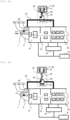
- Figs. 2A and 2B are diagrams illustrating an operation of the pressure type sealing plug in the analyzer.
- Fig. 2A illustrates a state of the vacuum pump 18, 22 during power application when power is fed to the analyzer 100.
- Fig. 2B illustrates a state of the vacuum pump 18, 22 during blackout when power feeding to the analyzer 100 stops.
- the pressure type sealing plug 41 can be configured to operate when the pressure difference formed through the bypass pipe 43 is switched by the vacuum valve 44.
- the plug hole 40 is provided in a structure that is bent in an L-shape.
- the plug hole 40 includes a section 40a that extends upward from the intermediate portion of the first pore 7, a section 40b that extends in the horizontal direction at an intermediate height, and a section 40c that extends upward from the intermediate height.
- the section 40a and the section 40b communicate with each other at a portion that is bent in an L-shape.
- the section 40b and the section 40c communicate with each other at a portion that is bent in an inverted L-shape.
- the hole diameter of the section 40a extending upward from the intermediate portion of the first pore 7 is the same as the outer diameter of the sealing plug 41.
- the hole diameter of the section 40b extending in the horizontal direction at an intermediate height is set to be less than the hole diameter of the section 40a extending upward from the intermediate portion of the first pore 7 or the outer diameter of the sealing plug 41.
- the hole diameter of the section 40c extending upward from the intermediate height is set not to interfere the passage of gas.
- the sealing plug 41 is inserted into the section 40a extending upward from the intermediate portion of the first pore 7.
- the sealing plug 41 in the section 40a extending upward from the intermediate portion of the first pore 7, the sealing plug 41 can be moved up and down due to the pressure difference and its own weight.
- the plug hole 40 can be opened to the intermediate portion of the first pore 7 while ensuring the connection of the bypass pipe 43 to the plug hole 40.
- the vacuum valve 44 has a function of stopping power application to switch the flow path of the bypass pipe 43 when blackout occurs.
- the vacuum valve 44 includes a valve element 45, a coil housing 46, a solenoid coil 47, a movable magnetic member 48, and a spring 49.
- the valve element 45 is movably provided, and includes a plurality of ports and a flow path through which the ports communicates with each other.
- the coil housing 46 accommodates the solenoid coil 47.
- the solenoid coil 47 is connected to a power supply (not illustrated), and generates an electromagnetic force by power application.
- the movable magnetic member 48 has magnetism and is provided to be movable by the electromagnetic force.
- a tip of the movable magnetic member 48 supports the valve element 45.
- a base of the movable magnetic member 48 is inserted into the solenoid coil 47 to advance to and retreat from the inside of the solenoid coil 47.
- the spring 49 elastically links the valve element 45 and the coil housing 46 to each other. The spring 49 biases the valve element 45 toward the coil housing 46 such that the valve element 45 is at a communication position where the valve element 45 communicates with the bypass pipe 43.
- the vacuum valve 44 is switchable between connection of the plug hole 40 and the analysis chamber 28 and connection of the plug hole 40 and a space in an atmospheric pressure environment in the flow path of the bypass pipe 43.
- the coil housing 46 two inlet ports and two outlet ports are provided.
- One inlet port is switched to be opened to and closed from the section on the analysis chamber 28 side of the bypass pipe 43.
- the other inlet port is switched to be opened to and closed from the space in the atmospheric pressure environment.
- One outlet port communicates with the one inlet port in the valve element 45, and is switched to be opened to and closed from the section on the plug hole 40 side of the bypass pipe 43.
- the other outlet port communicates with the other inlet port in the valve element 45, and is switched to be opened to and closed from the section on the plug hole 40 side of the bypass pipe 43.
- Fig. 2A when power is fed to the analyzer 100, power is applied to the solenoid coil 47.
- the solenoid coil 47 generates an electromagnetic force by power application, and aspirates and pulls up the movable magnetic member 48 with the electromagnetic force.
- the valve element 45 supported by the movable magnetic member 48 is maintained at the communication position where the valve element 45 communicates with the bypass pipe 43 against the biasing of the spring 49.
- the plug hole 40 and the analysis chamber 28 communicate with each other through the bypass pipe 43.
- the first pore 7 is at an intermediate pressure between the ion source container 9 and the first differential evacuation chamber 16.
- the analysis chamber 28 is maintained at a vacuum degree higher than that of the first differential evacuation chamber 16. Therefore, a portion of the plug hole 40 below the sealing plug 41 has a low vacuum degree close to the atmospheric pressure, and a portion of the plug hole 40 above the sealing plug 41 has a high vacuum degree.
- the plug hole 40 and the analysis chamber 28 do not communicate with each other through the bypass pipe 43, and the plug hole 40 is opened to the space in the atmospheric pressure environment.
- the first pore 7 is at an intermediate pressure between the ion source container 9 and the first differential evacuation chamber 16.
- air 50 flows from the space in the atmospheric pressure environment into the plug hole 40. Therefore, a portion of the plug hole 40 below the sealing plug 41 has a low vacuum degree close to the atmospheric pressure, and a portion of the plug hole 40 above the sealing plug 41 has a pressure close to the atmospheric pressure.
- the first pore 7 can be closed without power. Since the first pore 7 is closed, the inflow of gas into the aspiration side of the vacuum pump 18, 22 can be prevented.
- the sealing plug 41 penetrates into the first pore 7 without completely closing the first pore 7, the inflow rate of gas can be reduced to be lower than an allowable inflow rate when the turbomolecular pump 22 slows down. Therefore, a load on the blade of the vacuum pump 18, 22 can be reduced, and the vacuum pump 18, 22 can be protected.
- the sealing plug 41 is configured to operate due to a pressure difference between the ion source container 9 and the analysis chamber 28.
- the analysis chamber 28 is a space that is maintained at the maximum vacuum degree in the vacuum chamber 16, 19, 28. Therefore, when the bypass pipe 43 connects the plug hole 40 and the analysis chamber 28 to each other, the sealing plug 41 can easily float due to the pressure difference.
- the sealing plug 41 may be configured to operate due to a pressure difference between the ion source container 9 and the second differential evacuation chamber 19, or may be configured to operate due to a pressure difference between the ion source container 9 and the first differential evacuation chamber 16.
- the bypass pipe 43 may connect the plug hole 40 and the second differential evacuation chamber 19 or connect the plug hole 40 and the first differential evacuation chamber 16 to each other instead of the plug hole 40 and the analysis chamber 28.
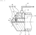
- Fig. 3 is a diagram illustrating a method of forming the plug hole in the analyzer.
- the plug hole 40 can be formed by drilling the iontophoresis electrode 6.
- the sections 40a, 40b, and 40c that communicate with each other at the bent portion can be formed.
- a through hole corresponding to the section 40a that extends upward from the intermediate portion of the first pore 7 a through hole corresponding to the section 40b that extends in the horizontal direction at an intermediate height, and a through hole corresponding to the section 40c that extends upward from the intermediate height are formed by turning.
- the sealing plug 41 is inserted into the section 40a extending upward from the intermediate portion of the first pore 7.
- a closing member 52 is pressed into each of the through holes, the plug hole 40 is formed.
- an appropriate material such as carbon steel or stainless steel can be used as long as heat resistance to a high temperature of about 200°C and the strength that can endure press fitting can be ensured.
- the iontophoresis electrode 6 can be formed of, for example, stainless steel.
- the iontophoresis electrode 6 and the first differential evacuation chamber 16 are airtightly sealed by an O-ring 51.
- the sealing plug 41 can be formed of metal such as carbon steel or stainless steel or ceramic such as silicon nitride. As long as the inflow rate of gas through the first pore 7 can be reduced to be lower than an allowable inflow rate when the vacuum pump 18, 22 slows down, the sealing plug 41 can be provided in an appropriate shape such as a spherical shape, a cylindrical shape, or a spindle shape. It should be noted that the sealing plug 41 needs to be provided in consideration of the weight of the sealing plug 41, a buoyancy force that is generated by the pressure difference formed through the bypass pipe 43, a frictional force with the inner wall of the plug hole 40, and the like.
- a buoyancy force F2 action on the sealing plug 41 is represented by F2 ⁇ 15.7 gf assuming that the vacuum degree of the lower portion of the sealing plug 41 during blackout is half of the atmospheric pressure.
- a frictional force F3 action on the sealing plug 41 is represented by F3 ⁇ 0.016 gf assuming that a frictional coefficient ⁇ between the sealing plug 41 and the inner wall of the plug hole 40 is 0.5. It is known that the frictional coefficient ⁇ increases even due to contact between different metals in a high vacuum degree.
- the sealing plug 41 can be provided such that the sealing plug 41 floats due to a pressure difference between the first pore 7 and the analysis chamber 28 during blackout at the assumed frictional coefficient ⁇ with the inner wall of the plug hole 40 and falls due to its own weight and a pressure difference between the first pore 7 and the atmospheric pressure during blackout.
- a small clearance may be formed between the sealing plug 41 and the inner wall of the plug hole 40.
- gas flows out from the first pore 7 to the analysis chamber 28.
- a clearance of about 10 ⁇ m or less is present between the sealing plug 41 and the inner wall of the plug hole 40, the outflow amount of gas can be reduced to be negligible.
- the sealing plug 41 can float due to a pressure difference during power feeding to the analyzer 100.
- an opening on the first pore 7 side of the plug hole 40 is provided on the upstream side where the ion source container 9 is present in the intermediate portion of the first pore 7.
- an opening on the first pore 7 side of the plug hole 40 is provided upstream of the iontophoresis electrode 6 provided in a conical shape.
- the pressure of the first pore 7 approaches the atmospheric pressure toward the upstream side where the ion source container 9 is present.
- the vacuum degree increases toward the downstream side where the first differential evacuation chamber 16 is present.
- the pressure difference formed through the bypass pipe 43 increases as the position of the plug hole 40 approaches the upstream side of the first pore 7, and thus the buoyancy force of the sealing plug 41 is easily ensured.
- the sealing plug 41 and the iontophoresis electrode 6 can also be formed of the same metal such as stainless steel.
- the hole diameter of the plug hole 40 increases during thermal expansion, gas may flow out from a clearance between the plug hole 40 and the sealing plug 41.
- the sealing plug 41 and the iontophoresis electrode 6 are formed of the same material, a difference in thermal elongation is reduced, and leakage of the gas can be prevented.
- the frictional coefficient ⁇ increases, and thus it is preferable to perform lubrication.
- a liquid lubricant may be applied to or a solid lubricant may be formed on the inner wall of the plug hole 40 in contact with the sealing plug 41.
- a kind having a low vapor pressure is preferable.
- perfluoropolyether such as FOMBLIN
- a fluorine-based lubricant such as polytetrafluoroethylene, or the like can be used.
- the solid lubricant molybdenum disulfide, tungsten disulfide, boron nitride, boric acid, polytetrafluoroethylene, chromium, silver, a lead alloy, or the like can be used.
- the solid lubricant can be formed by sputtering, ion plating, plating, or the like.
- mirror finishing for reducing the surface roughness may be performed on the inner wall of the plug hole 40 in contact with the sealing plug 41.
- mechanical polishing, electrolytic polishing, chemical polishing, or the like can be performed on the inner wall of the plug hole 40.
- Figs. 4, 5, and 6 are diagrams illustrating a structure example of the plug hole in the analyzer. Figs. 4, 5, and 6 correspond to an I-I line cross-sectional view of Fig. 3 .
- the diagram d2 of the sealing plug 41 can be set to be more than the hole diameter d1 of the first pore 7. That is, the hole diameter d3 of the plug hole 40 can be set to be more than the hole diameter d1 of the first pore 7.
- the height of a lower end of the sealing plug 41 can be set to be higher than the height of an upper end of the first pore 7 in a state where the sealing plug 41 floats.
- the plug hole 40 can form a stepwise wall around the first pore 7 in a traveling direction of the ions or the like transmitting through the first pore 7. In a portion where the plug hole 40 and the first pore 7 are connected, the flow of the ions or the like is likely to remain. In this location, foreign matter 54 is likely to be attached to the inner wall of the plug hole 40.
- the foreign matter 54 may be the ions 4 that are ionized from the sample or may be neutral particles or the like other than ions.
- the diagram d2 of the sealing plug 41 is set to be slightly more than the hole diameter d1 of the first pore 7. That is, it is preferable that the hole diameter d3 of the plug hole 40 is set to be slightly more than the hole diameter d1 of the first pore 7.
- a difference between the diameter d2 of the sealing plug 41 and the hole diameter d1 of the first pore 7 is preferably 1 mm or less, more preferably 500 ⁇ m or less, and still more preferably 100 ⁇ m or less.
- the diameter d2 of the sealing plug 41 is a length where the sealing plug 41 does not penetrate into the first pore 7 at normal temperature during thermal expansion.
- the height of the lower end of the sealing plug 41 is close to the height of the upper end of the first pore 7 in a state where the sealing plug 41 floats.
- a difference between the height of the lower end of the sealing plug 41 and the height of the upper end of the first pore 7 is preferably 5 mm or less and more preferably 1 mm or less.
- the amount of the foreign matter 54 attached to the inner wall of the plug hole 40 can be reduced. Therefore, a high analysis accuracy can be ensured. Even when the sealing plug 41 operates, a large amount of the foreign matter 54 does not peel off from the inner wall of the plug hole 40. Not only at the time of analysis restart after blackout but also in a state where power is fed to the analyzer 100, carry-over can be reduced.
- the sealing plug 41 can also be provided in a shape where a lower surface of the sealing plug 41 and an upper surface of the first pore 7 are substantially flush with each other in a floating state.
- the sealing plug 41 is provided in a cylindrical shape where the lower portion is cut out in a recessed shape.
- the lower portion of the sealing plug 41 is cut out in an arc shape at the same curvature as that of the first pore 7 in a cross-sectional view.
- a counterbore may or may not be provided in the bottom portion of the plug hole 40. From the viewpoint of reducing the remaining of the flow of the ions or the like, it is preferable that the counterbore is not provided.
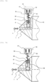
- Figs. 7A and 7B are diagrams illustrating an operation of an electromagnetic sealing plug in the analyzer.
- Fig. 7A illustrates a state of the vacuum pump 18, 22 during power application when power is fed to the analyzer 100.
- Fig. 7B illustrates a state of the vacuum pump 18, 22 during blackout when power feeding to the analyzer 100 stops.
- an electromagnetic type that is driven by an electromagnetic actuator 55 can also be provided.
- the plug hole 40 having a straight hole shape is connected to the first pore 7.
- One end of the plug hole 40 is opened to the intermediate portion of the first pore 7.
- Another end of the plug hole 40 is opened to the upper portion of the iontophoresis electrode 6.
- the sealing plug 41 supported by the electromagnetic actuator 55 is inserted into the plug hole 40 having a straight hole shape.
- the electromagnetic actuator 55 has a function of closing the first pore 7 with the sealing plug 41 by stopping power application during blackout.
- the electromagnetic actuator 55 includes a coil housing 56, a solenoid coil 57, a movable magnetic member 58, a spring 59, a shaft seal member 60, and an O-ring 61.
- the sealing plug 41 is fixed to one end of the movable magnetic member 58.
- the sealing plug 41 supported by the electromagnetic actuator 55 can be provided in an appropriate shape such as a spherical shape, a cylindrical shape, or a spindle shape.
- the coil housing 56 accommodates the solenoid coil 57.
- the solenoid coil 57 is connected to a power supply (not illustrated), and generates an electromagnetic force by power application.
- the movable magnetic member 58 has magnetism and is movable by the electromagnetic force.
- a tip of the movable magnetic member 58 is inserted into the plug hole 40 and supports the sealing plug 41.
- a base of the movable magnetic member 48 is inserted into the solenoid coil 57 to advance to and retreat from the inside of the solenoid coil 57.
- the spring 59 elastically links the coil housing 56 and the movable magnetic member 58 to each other. The spring 59 biases the movable magnetic member 58 toward the first pore 7 side such that the reaction force to the electromagnetic force is applied to the movable magnetic member 58.
- the shaft seal member 60 includes an opening in the upper portion of the plug hole 40.
- the shaft seal member 60 seals the plug hole 40 into which the movable magnetic member 58 is inserted in a state where the movable magnetic member 58 can advance and retreat.
- the O-ring 61 is accommodated in the shaft seal member 60.
- the O-ring 61 airtightly seals a slide portion with the movable magnetic member 58.
- the shaft seal member 60 or the O-ring 61 prevents leakage of gas through the plug hole 40.
- the sealing plug 41 supported by the electromagnetic actuator 55 closes the first pore 7.
- the sealing plug 41 supported by the electromagnetic actuator 55 is pulled up from the first pore 7 into the plug hole 40 due to the electromagnetic force of the electromagnetic actuator 55 to open the first pore 7.
- Fig. 7A when power is fed to the analyzer 100, power is applied to the solenoid coil 57.
- the solenoid coil 57 generates an electromagnetic force by power application, and aspirates and pulls up the movable magnetic member 58 with the electromagnetic force.
- the sealing plug 41 supported by the movable magnetic member 58 is pulled up from the first pore 7, is held in the plug hole 40, and opens the first pore 7.
- Fig. 7B when power feeding to the analyzer 100 stops, power application to the solenoid coil 57 stops.
- the solenoid coil 57 does not generate an electromagnetic force and does not pull up the movable magnetic member 58.
- the sealing plug 41 supported by the movable magnetic member 58 penetrates into the first pore 7 from the plug hole 40 and closes the first pore 7 according to the repulsive force of the spring 59 applied to the movable magnetic member 58.
- the electromagnetic actuator 55 has heat resistance.
- perfluoropolyether rubber such as VITON
- an fluorine-based elastomer such as polyvinylidene fluoride copolymer rubber
- the movable magnetic member 58, an adjacent portion to the movable magnetic member 58 and the coil housing 56, or a joined portion of the movable magnetic member 58 and the spring 59 has a highly heat-resistant structure.
- a heat-resistant material having a high thermal conductivity such as ceramic or a heat-resistant resin can be provided in an intermediate portion of the movable magnetic member 58, between the movable magnetic member 58 and the coil housing 56, or between the movable magnetic member 58 and the spring 59.
- the electromagnetic sealing plug 41 when power feeding to the analyzer 100 stops and power application to the vacuum pump 18, 22 stops, power application to the solenoid coil 57 also stops. Therefore, the first pore 7 can be closed without power. Since the first pore 7 is closed, the inflow of gas into the aspiration side of the vacuum pump 18, 22 can be prevented.
- the electromagnetic sealing plug 41 is limited in the disposition or the structure of the electromagnetic actuator 55 as compared to the pressure type sealing plug 41. However, the degree of freedom for designing the sealing plug 41 or the plug hole 40 increases.
- the present invention does not need to include all the configurations in the embodiment.
- a part of configurations in one embodiment may be replaced with other configurations, a part of configurations in one embodiment may be added to another embodiment, or a part of configurations in one embodiment may be omitted.
- the above-described analyzer 100 is a mass spectrometer.
- the analyzer including the sealing plug that can seal a pore through which charged particles are introduced into the vacuum chamber from the charged particle generation source is applicable to other analyzers as long as it includes a charged particle generation source that generates charged particles, a vacuum chamber of which an inside is evacuated, a pore through which the charged particles are introduced into the vacuum chamber from the charged particle generation source, a vacuum pump that is connected to the vacuum chamber.
- the other analyzer include a scanning electron microscope (SEM), a transmission electron microscope (TEM), and a focused ion beam (FIB) device.
Landscapes
- Chemical & Material Sciences (AREA)
- Analytical Chemistry (AREA)
- Physics & Mathematics (AREA)
- Engineering & Computer Science (AREA)
- Plasma & Fusion (AREA)
- Other Investigation Or Analysis Of Materials By Electrical Means (AREA)
Applications Claiming Priority (1)
| Application Number | Priority Date | Filing Date | Title |
|---|---|---|---|
| PCT/JP2022/016938 WO2023188410A1 (fr) | 2022-03-31 | 2022-03-31 | Dispositif d'analyse |
Publications (2)
| Publication Number | Publication Date |
|---|---|
| EP4503089A1 true EP4503089A1 (fr) | 2025-02-05 |
| EP4503089A4 EP4503089A4 (fr) | 2026-01-28 |
Family
ID=88200489
Family Applications (1)
| Application Number | Title | Priority Date | Filing Date |
|---|---|---|---|
| EP22933891.8A Pending EP4503089A4 (fr) | 2022-03-31 | 2022-03-31 | Dispositif d'analyse |
Country Status (5)
| Country | Link |
|---|---|
| US (1) | US20250226197A1 (fr) |
| EP (1) | EP4503089A4 (fr) |
| JP (1) | JP7693099B2 (fr) |
| CN (1) | CN118922911A (fr) |
| WO (1) | WO2023188410A1 (fr) |
Family Cites Families (7)
| Publication number | Priority date | Publication date | Assignee | Title |
|---|---|---|---|---|
| GB1497436A (en) * | 1975-03-11 | 1978-01-12 | Pye Ltd | Apparatus for the detection of volatile organic substance |
| JPS60113551U (ja) * | 1983-12-30 | 1985-08-01 | 株式会社島津製作所 | ガラス製ジエツト型分子セパレ−タ |
| JPH0668843A (ja) * | 1992-08-21 | 1994-03-11 | Hitachi Ltd | 大気圧イオン化質量分析計 |
| JPH09210965A (ja) * | 1996-01-31 | 1997-08-15 | Shimadzu Corp | 液体クロマトグラフ質量分析装置 |
| US7743790B2 (en) * | 2008-02-20 | 2010-06-29 | Varian, Inc. | Shutter and gate valve assemblies for vacuum systems |
| EP3324422B1 (fr) * | 2015-07-13 | 2019-08-07 | Shimadzu Corporation | Obturateur |
| GB2590351B (en) * | 2019-11-08 | 2024-01-03 | Thermo Fisher Scient Bremen Gmbh | Atmospheric pressure ion source interface |
-
2022
- 2022-03-31 CN CN202280093727.1A patent/CN118922911A/zh active Pending
- 2022-03-31 EP EP22933891.8A patent/EP4503089A4/fr active Pending
- 2022-03-31 JP JP2024511142A patent/JP7693099B2/ja active Active
- 2022-03-31 WO PCT/JP2022/016938 patent/WO2023188410A1/fr not_active Ceased
- 2022-03-31 US US18/850,757 patent/US20250226197A1/en active Pending
Also Published As
| Publication number | Publication date |
|---|---|
| WO2023188410A1 (fr) | 2023-10-05 |
| JPWO2023188410A1 (fr) | 2023-10-05 |
| JP7693099B2 (ja) | 2025-06-16 |
| CN118922911A (zh) | 2024-11-08 |
| US20250226197A1 (en) | 2025-07-10 |
| EP4503089A4 (fr) | 2026-01-28 |
Similar Documents
| Publication | Publication Date | Title |
|---|---|---|
| US7615765B2 (en) | Charged particle beam apparatus | |
| KR960012334B1 (ko) | 하전빔과 반응성가스를 사용해서 시료를 처리하는 방법 및 장치 | |
| CN103782364B (zh) | 带电粒子线装置、带电粒子线装置的调整方法及试样的检查或试样的观察方法 | |
| CN102792416A (zh) | 离子化装置及离子化分析装置 | |
| EP3291281B1 (fr) | Méthode pour transférer des ions | |
| US12176199B2 (en) | Ionization device and mass spectrometer | |
| US8063362B1 (en) | Ionic liquid membrane for air-to-vacuum sealing and ion transport | |
| US9666404B2 (en) | Charged particle source arrangement for a charged particle beam device, charged particle beam device for sample inspection, and method for providing a primary charged particle beam for sample inspection in a charged particle beam | |
| EP3776628B1 (fr) | Dispositif imr-ms | |
| CN104508791A (zh) | 环境扫描电子显微镜气体喷射系统 | |
| EP4503089A1 (fr) | Dispositif d'analyse | |
| CN114026671B (zh) | 质量分析装置 | |
| US20170347443A1 (en) | Ion Throughput Pump and Method | |
| JP4172561B2 (ja) | ガス分析装置 | |
| EP4362060A1 (fr) | Spectromètre de masse | |
| US12173712B2 (en) | Vacuum pumping system having a plurality of positive displacement vacuum pumps and method for operating the same | |
| WO2007102204A1 (fr) | Analyseur de masse | |
| JPH11162397A (ja) | イオンビーム照射装置 | |
| EP4730388A2 (fr) | Environnement de source d'électrons secs | |
| KR102587356B1 (ko) | 차동 진공 이온화 원 | |
| CN121075897A (zh) | 离子透镜组件、离子源、质谱仪以及质谱系统 | |
| JP2002042721A (ja) | イオン付着質量分析装置 | |
| CN121171876A (zh) | 一种基于辉光放电与四极杆质谱联用的分析仪器 | |
| KR20250176376A (ko) | 가스분석장치 및 이를 포함하는 기판처리시스템 | |
| CN120153308A (zh) | 用于分析样品的系统和方法 |
Legal Events
| Date | Code | Title | Description |
|---|---|---|---|
| STAA | Information on the status of an ep patent application or granted ep patent |
Free format text: STATUS: UNKNOWN |
|
| STAA | Information on the status of an ep patent application or granted ep patent |
Free format text: STATUS: THE INTERNATIONAL PUBLICATION HAS BEEN MADE |
|
| PUAI | Public reference made under article 153(3) epc to a published international application that has entered the european phase |
Free format text: ORIGINAL CODE: 0009012 |
|
| STAA | Information on the status of an ep patent application or granted ep patent |
Free format text: STATUS: REQUEST FOR EXAMINATION WAS MADE |
|
| 17P | Request for examination filed |
Effective date: 20240925 |
|
| AK | Designated contracting states |
Kind code of ref document: A1 Designated state(s): AL AT BE BG CH CY CZ DE DK EE ES FI FR GB GR HR HU IE IS IT LI LT LU LV MC MK MT NL NO PL PT RO RS SE SI SK SM TR |
|
| DAV | Request for validation of the european patent (deleted) | ||
| DAX | Request for extension of the european patent (deleted) | ||
| REG | Reference to a national code |
Ref country code: DE Ref legal event code: R079 Free format text: PREVIOUS MAIN CLASS: H01J0049240000 Ipc: H01J0049040000 |
|
| A4 | Supplementary search report drawn up and despatched |
Effective date: 20260102 |
|
| RIC1 | Information provided on ipc code assigned before grant |
Ipc: H01J 49/04 20060101AFI20251219BHEP Ipc: H01J 49/24 20060101ALI20251219BHEP Ipc: H01J 37/18 20060101ALI20251219BHEP |