EP4503120A1 - Feuille thermoconductrice - Google Patents
Feuille thermoconductrice Download PDFInfo
- Publication number
- EP4503120A1 EP4503120A1 EP23780595.7A EP23780595A EP4503120A1 EP 4503120 A1 EP4503120 A1 EP 4503120A1 EP 23780595 A EP23780595 A EP 23780595A EP 4503120 A1 EP4503120 A1 EP 4503120A1
- Authority
- EP
- European Patent Office
- Prior art keywords
- heat
- conductive sheet
- filler
- conductive
- anisotropic filler
- Prior art date
- Legal status (The legal status is an assumption and is not a legal conclusion. Google has not performed a legal analysis and makes no representation as to the accuracy of the status listed.)
- Pending
Links
Images
Classifications
-
- H—ELECTRICITY
- H05—ELECTRIC TECHNIQUES NOT OTHERWISE PROVIDED FOR
- H05K—PRINTED CIRCUITS; CASINGS OR CONSTRUCTIONAL DETAILS OF ELECTRIC APPARATUS; MANUFACTURE OF ASSEMBLAGES OF ELECTRICAL COMPONENTS
- H05K7/00—Constructional details common to different types of electric apparatus
- H05K7/20—Modifications to facilitate cooling, ventilating, or heating
- H05K7/2029—Modifications to facilitate cooling, ventilating, or heating using a liquid coolant with phase change in electronic enclosures
-
- C—CHEMISTRY; METALLURGY
- C08—ORGANIC MACROMOLECULAR COMPOUNDS; THEIR PREPARATION OR CHEMICAL WORKING-UP; COMPOSITIONS BASED THEREON
- C08J—WORKING-UP; GENERAL PROCESSES OF COMPOUNDING; AFTER-TREATMENT NOT COVERED BY SUBCLASSES C08B, C08C, C08F, C08G or C08H
- C08J5/00—Manufacture of articles or shaped materials containing macromolecular substances
- C08J5/18—Manufacture of films or sheets
-
- C—CHEMISTRY; METALLURGY
- C08—ORGANIC MACROMOLECULAR COMPOUNDS; THEIR PREPARATION OR CHEMICAL WORKING-UP; COMPOSITIONS BASED THEREON
- C08K—Use of inorganic or non-macromolecular organic substances as compounding ingredients
- C08K3/00—Use of inorganic substances as compounding ingredients
- C08K3/02—Elements
- C08K3/04—Carbon
-
- C—CHEMISTRY; METALLURGY
- C08—ORGANIC MACROMOLECULAR COMPOUNDS; THEIR PREPARATION OR CHEMICAL WORKING-UP; COMPOSITIONS BASED THEREON
- C08K—Use of inorganic or non-macromolecular organic substances as compounding ingredients
- C08K3/00—Use of inorganic substances as compounding ingredients
- C08K3/02—Elements
- C08K3/08—Metals
-
- C—CHEMISTRY; METALLURGY
- C08—ORGANIC MACROMOLECULAR COMPOUNDS; THEIR PREPARATION OR CHEMICAL WORKING-UP; COMPOSITIONS BASED THEREON
- C08K—Use of inorganic or non-macromolecular organic substances as compounding ingredients
- C08K3/00—Use of inorganic substances as compounding ingredients
- C08K3/18—Oxygen-containing compounds, e.g. metal carbonyls
- C08K3/20—Oxides; Hydroxides
- C08K3/22—Oxides; Hydroxides of metals
-
- C—CHEMISTRY; METALLURGY
- C08—ORGANIC MACROMOLECULAR COMPOUNDS; THEIR PREPARATION OR CHEMICAL WORKING-UP; COMPOSITIONS BASED THEREON
- C08K—Use of inorganic or non-macromolecular organic substances as compounding ingredients
- C08K5/00—Use of organic ingredients
- C08K5/54—Silicon-containing compounds
- C08K5/541—Silicon-containing compounds containing oxygen
- C08K5/5415—Silicon-containing compounds containing oxygen containing at least one Si—O bond
- C08K5/5419—Silicon-containing compounds containing oxygen containing at least one Si—O bond containing at least one Si—C bond
-
- C—CHEMISTRY; METALLURGY
- C08—ORGANIC MACROMOLECULAR COMPOUNDS; THEIR PREPARATION OR CHEMICAL WORKING-UP; COMPOSITIONS BASED THEREON
- C08K—Use of inorganic or non-macromolecular organic substances as compounding ingredients
- C08K7/00—Use of ingredients characterised by shape
- C08K7/02—Fibres or whiskers
- C08K7/04—Fibres or whiskers inorganic
- C08K7/06—Elements
-
- C—CHEMISTRY; METALLURGY
- C08—ORGANIC MACROMOLECULAR COMPOUNDS; THEIR PREPARATION OR CHEMICAL WORKING-UP; COMPOSITIONS BASED THEREON
- C08L—COMPOSITIONS OF MACROMOLECULAR COMPOUNDS
- C08L83/00—Compositions of macromolecular compounds obtained by reactions forming in the main chain of the macromolecule a linkage containing silicon with or without sulfur, nitrogen, oxygen or carbon only; Compositions of derivatives of such polymers
- C08L83/04—Polysiloxanes
-
- C—CHEMISTRY; METALLURGY
- C08—ORGANIC MACROMOLECULAR COMPOUNDS; THEIR PREPARATION OR CHEMICAL WORKING-UP; COMPOSITIONS BASED THEREON
- C08L—COMPOSITIONS OF MACROMOLECULAR COMPOUNDS
- C08L83/00—Compositions of macromolecular compounds obtained by reactions forming in the main chain of the macromolecule a linkage containing silicon with or without sulfur, nitrogen, oxygen or carbon only; Compositions of derivatives of such polymers
- C08L83/04—Polysiloxanes
- C08L83/08—Polysiloxanes containing silicon bound to organic groups containing atoms other than carbon, hydrogen and oxygen
-
- C—CHEMISTRY; METALLURGY
- C09—DYES; PAINTS; POLISHES; NATURAL RESINS; ADHESIVES; COMPOSITIONS NOT OTHERWISE PROVIDED FOR; APPLICATIONS OF MATERIALS NOT OTHERWISE PROVIDED FOR
- C09K—MATERIALS FOR MISCELLANEOUS APPLICATIONS, NOT PROVIDED FOR ELSEWHERE
- C09K5/00—Heat-transfer, heat-exchange or heat-storage materials, e.g. refrigerants; Materials for the production of heat or cold by chemical reactions other than by combustion
- C09K5/02—Materials undergoing a change of physical state when used
- C09K5/06—Materials undergoing a change of physical state when used the change of state being from liquid to solid or vice versa
-
- H—ELECTRICITY
- H05—ELECTRIC TECHNIQUES NOT OTHERWISE PROVIDED FOR
- H05K—PRINTED CIRCUITS; CASINGS OR CONSTRUCTIONAL DETAILS OF ELECTRIC APPARATUS; MANUFACTURE OF ASSEMBLAGES OF ELECTRICAL COMPONENTS
- H05K7/00—Constructional details common to different types of electric apparatus
- H05K7/20—Modifications to facilitate cooling, ventilating, or heating
-
- H—ELECTRICITY
- H05—ELECTRIC TECHNIQUES NOT OTHERWISE PROVIDED FOR
- H05K—PRINTED CIRCUITS; CASINGS OR CONSTRUCTIONAL DETAILS OF ELECTRIC APPARATUS; MANUFACTURE OF ASSEMBLAGES OF ELECTRICAL COMPONENTS
- H05K7/00—Constructional details common to different types of electric apparatus
- H05K7/20—Modifications to facilitate cooling, ventilating, or heating
- H05K7/2039—Modifications to facilitate cooling, ventilating, or heating characterised by the heat transfer by conduction from the heat generating element to a dissipating body
- H05K7/20436—Inner thermal coupling elements in heat dissipating housings, e.g. protrusions or depressions integrally formed in the housing
-
- H—ELECTRICITY
- H05—ELECTRIC TECHNIQUES NOT OTHERWISE PROVIDED FOR
- H05K—PRINTED CIRCUITS; CASINGS OR CONSTRUCTIONAL DETAILS OF ELECTRIC APPARATUS; MANUFACTURE OF ASSEMBLAGES OF ELECTRICAL COMPONENTS
- H05K7/00—Constructional details common to different types of electric apparatus
- H05K7/20—Modifications to facilitate cooling, ventilating, or heating
- H05K7/2039—Modifications to facilitate cooling, ventilating, or heating characterised by the heat transfer by conduction from the heat generating element to a dissipating body
- H05K7/20436—Inner thermal coupling elements in heat dissipating housings, e.g. protrusions or depressions integrally formed in the housing
- H05K7/20445—Inner thermal coupling elements in heat dissipating housings, e.g. protrusions or depressions integrally formed in the housing the coupling element being an additional piece, e.g. thermal standoff
- H05K7/20472—Sheet interfaces
- H05K7/20481—Sheet interfaces characterised by the material composition exhibiting specific thermal properties
-
- H—ELECTRICITY
- H10—SEMICONDUCTOR DEVICES; ELECTRIC SOLID-STATE DEVICES NOT OTHERWISE PROVIDED FOR
- H10W—GENERIC PACKAGES, INTERCONNECTIONS, CONNECTORS OR OTHER CONSTRUCTIONAL DETAILS OF DEVICES COVERED BY CLASS H10
- H10W40/00—Arrangements for thermal protection or thermal control
- H10W40/70—Fillings or auxiliary members in containers or in encapsulations for thermal protection or control
- H10W40/73—Fillings or auxiliary members in containers or in encapsulations for thermal protection or control for cooling by change of state
-
- C—CHEMISTRY; METALLURGY
- C08—ORGANIC MACROMOLECULAR COMPOUNDS; THEIR PREPARATION OR CHEMICAL WORKING-UP; COMPOSITIONS BASED THEREON
- C08G—MACROMOLECULAR COMPOUNDS OBTAINED OTHERWISE THAN BY REACTIONS ONLY INVOLVING UNSATURATED CARBON-TO-CARBON BONDS
- C08G77/00—Macromolecular compounds obtained by reactions forming a linkage containing silicon with or without sulfur, nitrogen, oxygen or carbon in the main chain of the macromolecule
- C08G77/04—Polysiloxanes
- C08G77/12—Polysiloxanes containing silicon bound to hydrogen
-
- C—CHEMISTRY; METALLURGY
- C08—ORGANIC MACROMOLECULAR COMPOUNDS; THEIR PREPARATION OR CHEMICAL WORKING-UP; COMPOSITIONS BASED THEREON
- C08G—MACROMOLECULAR COMPOUNDS OBTAINED OTHERWISE THAN BY REACTIONS ONLY INVOLVING UNSATURATED CARBON-TO-CARBON BONDS
- C08G77/00—Macromolecular compounds obtained by reactions forming a linkage containing silicon with or without sulfur, nitrogen, oxygen or carbon in the main chain of the macromolecule
- C08G77/04—Polysiloxanes
- C08G77/20—Polysiloxanes containing silicon bound to unsaturated aliphatic groups
-
- C—CHEMISTRY; METALLURGY
- C08—ORGANIC MACROMOLECULAR COMPOUNDS; THEIR PREPARATION OR CHEMICAL WORKING-UP; COMPOSITIONS BASED THEREON
- C08J—WORKING-UP; GENERAL PROCESSES OF COMPOUNDING; AFTER-TREATMENT NOT COVERED BY SUBCLASSES C08B, C08C, C08F, C08G or C08H
- C08J2383/00—Characterised by the use of macromolecular compounds obtained by reactions forming in the main chain of the macromolecule a linkage containing silicon with or without sulfur, nitrogen, oxygen, or carbon only; Derivatives of such polymers
- C08J2383/04—Polysiloxanes
-
- C—CHEMISTRY; METALLURGY
- C08—ORGANIC MACROMOLECULAR COMPOUNDS; THEIR PREPARATION OR CHEMICAL WORKING-UP; COMPOSITIONS BASED THEREON
- C08K—Use of inorganic or non-macromolecular organic substances as compounding ingredients
- C08K3/00—Use of inorganic substances as compounding ingredients
- C08K3/02—Elements
- C08K3/08—Metals
- C08K2003/0812—Aluminium
-
- C—CHEMISTRY; METALLURGY
- C08—ORGANIC MACROMOLECULAR COMPOUNDS; THEIR PREPARATION OR CHEMICAL WORKING-UP; COMPOSITIONS BASED THEREON
- C08K—Use of inorganic or non-macromolecular organic substances as compounding ingredients
- C08K3/00—Use of inorganic substances as compounding ingredients
- C08K3/18—Oxygen-containing compounds, e.g. metal carbonyls
- C08K3/20—Oxides; Hydroxides
- C08K3/22—Oxides; Hydroxides of metals
- C08K2003/2227—Oxides; Hydroxides of metals of aluminium
-
- C—CHEMISTRY; METALLURGY
- C08—ORGANIC MACROMOLECULAR COMPOUNDS; THEIR PREPARATION OR CHEMICAL WORKING-UP; COMPOSITIONS BASED THEREON
- C08K—Use of inorganic or non-macromolecular organic substances as compounding ingredients
- C08K2201/00—Specific properties of additives
- C08K2201/001—Conductive additives
-
- C—CHEMISTRY; METALLURGY
- C08—ORGANIC MACROMOLECULAR COMPOUNDS; THEIR PREPARATION OR CHEMICAL WORKING-UP; COMPOSITIONS BASED THEREON
- C08K—Use of inorganic or non-macromolecular organic substances as compounding ingredients
- C08K2201/00—Specific properties of additives
- C08K2201/002—Physical properties
- C08K2201/004—Additives being defined by their length
-
- C—CHEMISTRY; METALLURGY
- C08—ORGANIC MACROMOLECULAR COMPOUNDS; THEIR PREPARATION OR CHEMICAL WORKING-UP; COMPOSITIONS BASED THEREON
- C08K—Use of inorganic or non-macromolecular organic substances as compounding ingredients
- C08K2201/00—Specific properties of additives
- C08K2201/002—Physical properties
- C08K2201/005—Additives being defined by their particle size in general
-
- C—CHEMISTRY; METALLURGY
- C08—ORGANIC MACROMOLECULAR COMPOUNDS; THEIR PREPARATION OR CHEMICAL WORKING-UP; COMPOSITIONS BASED THEREON
- C08K—Use of inorganic or non-macromolecular organic substances as compounding ingredients
- C08K2201/00—Specific properties of additives
- C08K2201/016—Additives defined by their aspect ratio
-
- H—ELECTRICITY
- H10—SEMICONDUCTOR DEVICES; ELECTRIC SOLID-STATE DEVICES NOT OTHERWISE PROVIDED FOR
- H10W—GENERIC PACKAGES, INTERCONNECTIONS, CONNECTORS OR OTHER CONSTRUCTIONAL DETAILS OF DEVICES COVERED BY CLASS H10
- H10W40/00—Arrangements for thermal protection or thermal control
- H10W40/20—Arrangements for cooling
- H10W40/25—Arrangements for cooling characterised by their materials
- H10W40/251—Organics
-
- H—ELECTRICITY
- H10—SEMICONDUCTOR DEVICES; ELECTRIC SOLID-STATE DEVICES NOT OTHERWISE PROVIDED FOR
- H10W—GENERIC PACKAGES, INTERCONNECTIONS, CONNECTORS OR OTHER CONSTRUCTIONAL DETAILS OF DEVICES COVERED BY CLASS H10
- H10W40/00—Arrangements for thermal protection or thermal control
- H10W40/70—Fillings or auxiliary members in containers or in encapsulations for thermal protection or control
Definitions
- the present invention relates to a heat-conductive sheet.
- heat-dissipating elements such as heat sinks are generally used to dissipate heat generated from heating elements such as semiconductor elements and machine parts. It is known that a heat-conductive sheet is disposed between a heating element and a heat-dissipating element for the purpose of increasing the efficiency of heat transfer to the heat-dissipating element. Heat-conductive sheets are generally used in a compressed state when disposed inside electronic devices, and therefore require high flexibility and further require increased thermal conductivity in order to enhance heat dissipation.
- the heat-conductive sheet is required to have a followability to the heating element and the heat-dissipating element in order to further enhance the conduction efficiency.
- a phase-change-type heat-conductive sheet a so-called phase change sheet, which is softened or melted by heating, has been studied.
- PTL 1 discloses a heat-dissipation sheet that at least comprises an alkyl group-introduced silicone oil, an alphaolefin, and heat-conductive filler, wherein the heat-dissipation sheet is putty-like at normal temperature and is softened to be fluidized by heating.
- a heat-conductive sheet highly filled with CPAO is also known as a heat-conductive sheet.
- PTL 2 discloses a heat-curable resin composition containing CPAO and a heat-curable resin, and a molded sheet product thereof.
- a technique in which a graphite material having high thermal conductivity is oriented in the thickness direction from the heating element to the heat-dissipating element. Further, in view of reducing contact heat resistance, the surface roughness may be reduced. However, once the surface roughness is reduced to a certain level, it is difficult to further reduce it, and reducing the surface roughness does not necessarily reduce the heat resistance value.
- the present invention provides [1] to [12] below.
- the present invention can provide a heat-conductive sheet in which the heat resistance value can be sufficiently reduced.
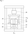
- Fig. 1 is a schematic view of a heat resistance value measuring machine.
- the heat-conductive sheet of the present invention is a heat-conductive sheet comprising a binder and a heat-conductive filler dispersed in the binder, that is used in a state of being sandwiched between a heating element and a heat-dissipating element.
- the reflectance of the surface in contact with the heating element or the heat-dissipating element (hereinafter, also simply referred to as "reflectance") is 0.30% or more.
- the reflectance is less than 0.30%, the heat resistance value of the heat-conductive sheet increases, the adhesive strength of the heat-conductive sheet to the heat-dissipating element or heating element is impaired, and gaps are generated between the heating element or heat-dissipating element and the heat-conductive sheet, which prevents the heat-conductive sheet from sufficiently demonstrating thermal conductivity.
- At least one of the surface in contact with the heating element and the surface in contact with the heat-dissipating element may have a reflectance of 0.30% or more, but it is preferable that both surfaces have a reflectance of 0.30% or more.
- both surfaces have a reflectance of 0.30% or more, the heat-conductive sheet can be adhered to both heat-dissipating element and heating element, and its heat resistance value can be even further reduced.
- the reflectance in view of enhancing adhesion and more effectively reducing the heat resistance value, is preferably 0.45% or more, more preferably 0.50% or more, further preferably 0.55% or more.
- the upper limit of the reflectance is not specifically limited, but is practically, for example, 4.0% or less, preferably 3.5% or less, more preferably 2.0% or less.
- the reflectance can be obtained by the measurement method described in the Examples described later.
- the heat-conductive sheet of the present invention preferably has no fluidity in 0 to 100°C.
- no fluidity means that the components constituting the heat-conductive sheet do not flow out of the heat-conductive sheet when it is heated from 0°C to 100°C.
- the heat-conductive sheet should be able to retain its shape even when heated to 100°C. In this case, the heat-conductive sheet may slightly change shape when heated, but this essentially remains an elastic deformation, and the heat-conductive sheet can return to its original shape after being cooled.
- the shape of the heat-conductive sheet can be substantially retained without the components of the heat-conductive sheet flowing out due to the heat generated by the heating element when the heat-conductive sheet is used in a state of being sandwiched between a heat-dissipating element and a heating element.
- good thermal conductivity can be exhibited.
- the shape of the heat-conductive sheet should be retained even when the heat-conductive sheet is heated to a temperature higher than the melting point of the phase change material.
- the phase change material itself may melt, but the melted phase change material should not flow out.
- the binder used in the heat-conductive sheet of the present invention is a polymer compound such as elastomer , rubber, or the like, and is preferably a product formed by curing a liquid polymer composition (curable polymer composition) composed of a mixture system such as a base resin and a curing agent.
- the curable polymer composition may be composed of uncrosslinked rubber and a crosslinking agent, or may contain a monomer, prepolymer, or the like, and a curing agent.
- the above curing reaction may be normal temperature curing or heat curing.
- the binder formed from the curable polymer composition is preferably a crosslinked matrix with a crosslinked structure. Further, examples of the binder preferably include a silicone matrix.
- the silicone matrix is preferably silicone having no fluidity at any of room temperature (23°C) and high temperature (80°C). Since the silicone matrix has no fluidity, the shape retention of the heat-conductive sheet can be ensured at normal temperature and high temperature.
- silicone rubber may be used as the silicone matrix in the present invention.
- Use of silicone rubber facilitates compressive deformation so that the heat-conductive sheet can be installed easily between a heating element and a heat-dissipating element. Further, use of silicone rubber can impart a certain compression characteristic to the heat-conductive sheet, so that the reliability can be enhanced.
- the silicone to be used for the silicone matrix may be any of the condensation reaction type and the addition reaction type, and is preferably the addition reaction type because of the following reasons: a large amount of the heat-conductive filler is easily filled therein, and the curing temperature can be easily adjusted by a catalyst or the like.
- the silicone matrix can be obtained, for example, by curing a curable silicone composition.
- the curable silicone composition may be formed, for example, of a base resin and a curing agent.
- the curable silicone composition is of the addition reaction type, it preferably contains an alkenyl group-containing organopolysiloxane as a base resin and hydrogen organopolysiloxane as a curing agent, in view of ease of filling a large amount of the heat-conductive filler.
- the curable silicone composition is preferably in a liquid form before cured.
- a liquid form means a liquid at normal temperature (23°C) and under 1 atm.
- a crosslinked silicone more preferable to use a three-dimensionally crosslinked silicone matrix as the silicone matrix, in view of ensuring the shape retention of the heat-conductive sheet.
- this purpose may be achieved by curing a curable silicone composition containing: an alkenyl group-containing organopolysiloxane having at least three or more alkenyl groups in one molecule; or a hydrogen organopolysiloxane having at least three or more hydrogen atoms added to a silicon atoms.
- the content of the silicone matrix may be, for example, about 5 to 50 mass%, preferably 8 to 35 mass%, more preferably 12 to 25 mass%, with respect to the total amount of the heat-conductive sheet.
- the binder component preferably contains a phase change material.
- the flexibility can be increased when heating, and the adhesion to the heating element or heat-dissipating element is significantly more easily increased. It also makes it easier to improve the reflectance of the surfaces of the heat-conductive sheet.
- a heat-conductive sheet with increased adhesive strength is beneficial in the following applications. For example, since substrates are thin in miniaturized and highly integrated semiconductors, the thinner the substrate becomes, the more likely warping of the substrate due to heat generation is to occur. On the other hand, since heat-conductive sheets generally have rebound resilience, they can easily absorb changes in thickness by having a certain degree of thickness, and have been suitably used without gaps even when warping of the substrate occurred. However, when the heat-conductive sheet has its thickness reduced as described above, it less readily absorbs changes in thickness when used in a compressed state. Therefore, it has become necessary to increase the adhesion to the heat-dissipating element or heating element so that the space between the heat-dissipating element and heating element can be filled without gaps even when warping of the substrate or the like occurs.
- the phase change material is a material that changes from solid to liquid upon heating.
- the phase change material may be a compound that is liquid at room temperature (23°C) or a compound that is capable of being melted by heating at a certain temperature (for example, a temperature over 23°C and 80°C or less), but in view of easily increasing flexibility when heated, it is preferably in a solid form at room temperature and under 1 atm. Accordingly, the melting point of the phase change material is preferably higher than normal temperature (23°C), more preferably 30°C or more, further preferably 35°C or more.
- the melting point of the phase change material is preferably 80°C or less, more preferably 70°C or less, further preferably 60°C or less, even more preferably 50°C or less, in view of melting the material by heating at high temperature (for example, 80°C).
- the melting point of the phase change material is the temperature of the endothermic peak in the DTA curve measured using thermogravimetric differential thermal analysis (TGDTA) at a heating rate of 1°C/min. Further, in the case where the alkyl silicone is a mixture of the phase change material, the melting point is the maximum endothermic peak in the aforementioned temperature range.
- phase change material examples include liquid paraffin, paraffin waxes, vaseline, polyalphaolefin (PAO), alkyl silicone, polyethylene waxes, and polypropylene waxes.
- Vaseline is a semi-solid hydrocarbon compound, which is a mixture of a plurality of hydrocarbon compounds including isoparaffin, cycloparaffin, and naphthene. Examples of vaseline can also include white vaseline defined in the Japanese Pharmacopoeia.
- paraffin waxes, vaseline, polyalphaolefin (PAO), alkyl silicones, polyethylene waxes, and polypropylene waxes are preferable, and polyalphaolefin (PAO) and alkyl silicones are more preferable, in view of effectively increasing the reflectance of the surfaces of the heat-conductive sheet.
- Polyalphaolefin is a polymer of alpha-olefins.
- the type of the alpha-olefins is not particularly limited, and they may have a linear or branched chain, or a cyclic structure.
- Polyalphaolefin is, for example, a polymer of alpha-olefins having 2 to 30 carbon atoms, preferably having 6 to 20 carbon atoms. The number of carbon atoms of alpha-olefins may be increased, for example, so that the crystalline polyalphaolefin may be a side-chain crystalline polyalphaolefin.
- Polyalphaolefin may be a polymer of single alpha-olefins or may be a copolymer of two or more alpha-olefins.
- alkyl silicone examples include compounds having a polysiloxane backbone on the main chain and an alkyl group.
- the alkyl group is an alkyl group bound to a silicon atom, and preferably includes alkyl groups having 8 or more carbon atoms.
- an alkyl silicone represented by the following formula (1) is preferable.
- R indicates an alkyl group having 8 or more carbon atoms
- m and n are integers where m:n is in the range of 100:0 to 50:50. Further, the sum of m and n is 20 or more and 1000 or less.
- the alkyl group having 8 or more carbon atoms may be a straight-chain alkyl group or a branched chain alkyl group, but it is preferably a straight-chain alkyl group.
- the number of carbon atoms of the alkyl group is preferably in the range of 8 to 26, and more preferably in the range of 12 to 22.
- R is an alkyl group having 8 or more carbon atoms
- the melting point of the alkyl silicone can be prevented from being too low.
- R is an alkyl group having 26 or less carbon atoms
- an alkyl silicone with a melting point of 80°C or less is more easily obtained.
- R is not specifically limited, but is preferably a dodecyl group, a tetradecyl group, a pentadecyl group, a hexadecyl group, a heptadecyl group, an octadecyl group, a nonadecyl group, an icosyl group, a henicosyl group, a docosyl group, and the like, and more preferably an octadecyl group.
- the properties of the alkyl silicone become similar to those of so-called hard resins at temperatures equal to or below its melting point, and when m:n gets closer to 50:50, it becomes to have more wax-like properties.
- using an appropriate amount of alkyl silicone with an m:n of 100:0 allows to make the heat-conductive sheet harder to a certain degree and to improve the handleability.
- the alkyl silicone may be an alkyl silicone other than the compound represented by the formula (1) described above, and may be, for example, an alkyl silicone having a substituent other than an alkyl group.
- PAO polyalphaolefin
- alkyl silicone allows to more effectively increase the reflectance of the surfaces of the heat-conductive sheet.
- phase change material may be contained alone, or two or more types of them may be contained in combination.
- the content of the phase change material is preferably 1 to 45 parts by mass, more preferably 2 to 30 parts by mass, further preferably 5 to 20 parts by mass, with respect to 100 parts by mass of the binder.
- the content of the phase change material is the aforementioned lower limit or more, the reflectance of the surfaces of the heat-conductive sheet can be effectively improved.
- the content ratio of the binder component can be a certain level or more and the adhesive strength of the heat-conductive sheet can be increased, which allows to also effectively improve the reflectance.
- a heat-conductive filler is preferably dispersed in the binder to be held by the binder.
- the heat-conductive filler may be an anisotropic filler or a non-anisotropic filler, or both of them may be used in combination.
- the heat-conductive filler preferably includes at least an anisotropic filler, more preferably includes both of an anisotropic filler and a non-anisotropic filler.
- the heat-conductive sheet tends to enhance the thermal conductivity when containing an anisotropic filler.
- the anisotropic filler is preferably oriented in one direction, and specifically, preferably oriented in the thickness direction of the heat-conductive sheet.
- the anisotropic filler is oriented in the thickness direction, the thermal conductivity in the thickness direction tends to be enhanced.
- the long-axis direction is not necessarily strictly parallel to the thickness direction, and the long-axis direction inclined to some extent in the thickness direction is also considered to be oriented in the thickness direction.
- those with the long-axis direction inclined at about less than 20° are also considered to be an anisotropic filler oriented in the thickness direction, and when such anisotropic filler are predominant (for example, over 60%, preferably over 80%, with respect to the total number of particles of the anisotropic filler) in the heat-conductive sheet, they are considered to be oriented in the thickness direction.
- the anisotropic filler has been explained on the premise that they are oriented in the thickness direction; however, the same applies to the case where they are oriented in another direction.
- the heat-conductive sheet preferably contains a graphite material.
- the thermal conductivity tends to be further enhanced when a graphite material is contained.
- the reflectance generally tends to be lower when a graphite material is contained than when a graphite material is not contained.
- the adhesive strength and thermal conductivity is easily enhanced by having a reflectance of a certain value or more as described above.
- the graphite material may be an anisotropic filler or a non-anisotropic material, but it is preferably an anisotropic filler.
- the content of the heat-conductive filler is preferably 150 to 3000 parts by mass, more preferably 200 to 2000 parts by mass, further preferably 300 to 1000 parts by mass, with respect to 100 parts by mass of the binder.
- the content of the heat-conductive filler is 150 parts by mass or more, a certain thermal conductivity can be imparted to the heat-conductive sheet.
- the reflectance of the heat-conductive sheet can be a certain level or more.
- the ratio of the binder in the heat-conductive sheet can also be a certain level or more, which increases the adhesive strength of the heat-conductive sheet and allows to reduce the heat resistance value.
- the anisotropic filler is a filler that has an anisotropic shape and is capable of being oriented.
- Examples of the anisotropic filler include fiber materials and flaky materials.
- the anisotropic filler has a high aspect ratio, specifically, an aspect ratio of over 2, and preferably has an aspect ratio of 5 or more.
- An anisotropic filler having the aspect ratio over 2 easily orients in one direction, for example, the thickness direction, and thus the thermal conductivity in the one direction, for example, the thickness direction of the heat-conductive sheet is easily enhanced. Further, the upper limit of the aspect ratio is not specifically limited, but is practically 100.
- the aspect ratio is the ratio of the length in the long-axis direction to the length in the short-axis direction of the anisotropic filler.
- the aspect ratio means the fiber length/the fiber diameter when it is a fiber material, and means the length in the long-axis direction of a flake/the thickness thereof when it is a flaky material.
- the content of the anisotropic filler in the heat-conductive sheet is preferably 10 to 500 parts by mass, more preferably 30 to 300 parts by mass, further preferably 50 to 250 parts by mass, with respect to 100 parts by mass of the binder.
- the content of the anisotropic filler is 10 parts by mass or more, the thermal conductivity is easily enhanced. Further, when it is 500 parts by mass or less, the viscosity of the mixed composition, which will be described below, tends to be appropriate, and the orientation of the anisotropic filler is enhanced. Further, the dispersibility of the anisotropic filler in the binder is also enhanced.
- the average fiber length is preferably 10 to 500 ⁇ m, more preferably 20 to 350 ⁇ m, further preferably 50 to 300 ⁇ m. Fibers of an anisotropic filler having an average fiber length of 10 ⁇ m or more are appropriately in contact with each other inside the heat-conductive sheet, to ensure a heat transfer path, so that the thermal conductivity of the heat-conductive sheet is enhanced.
- the anisotropic filler has an average fiber length of 500 ⁇ m or less, the bulk of the anisotropic filler is low, so that a large amount thereof can be filled in the binder component.
- the average fiber length of fiber materials is preferably shorter than the thickness of the heat-conductive sheet.
- the average fiber length shorter than the thickness prevents the fiber materials from protruding from the surface of the heat-conductive sheet more than necessary.
- the average fiber length can be calculated through observing the anisotropic filler with a microscope. More specifically, the fiber lengths of any 50 fibers of the anisotropic filler are measured, for example, using an electron microscope or optical microscope, and the average (arithmetic mean) thereof can be taken as an average fiber length.
- the average particle size is preferably 10 to 400 ⁇ m, more preferably 15 to 300 ⁇ m, further preferably 20 to 200 ⁇ m. Flakes of the anisotropic filler having an average particle size of 10 ⁇ m or more are easily in contact with each other in the heat-conductive sheet, to surely create a heat transfer path, so that the thermal conductivity of the heat-conductive sheet is enhanced.
- the anisotropic filler has an average particle size of 400 ⁇ m or less, the bulk of the heat-conductive sheet to be low, so that a large amount of the anisotropic filler can be filled in the binder component.
- the average particle size of the flaky material can be calculated by observing the anisotropic filler with a microscope and determining the major diameter as a diameter. More specifically, the major diameters of any 50 flakes of anisotropic filler are measured, for example, using an electron microscope or optical microscope, and the average (arithmetic mean) thereof can be taken as an average particle size.
- any known material having a thermal conductivity may be used.
- the anisotropic filler is preferably diamagnetic in the case where it is to be oriented by the magnetic field orientation, as will be described below.
- the anisotropic filler may not be diamagnetic in the case where it is to be oriented by fluidized orientation or not oriented.
- the anisotropic filler include carbon materials typified by carbon fibers and flaky carbon powder, metal materials typified by metal fibers, and metal oxides, boron nitride, metal nitride, metal carbide, metal hydroxide, and polyparaphenylene benzoxazole fibers.
- carbon materials are preferable in view of having a small specific gravity and a good dispersibility in the binder component.
- graphite materials having a high thermal conductivity are more preferable.
- a graphite material is diamagnetic when the graphite planes are aligned in a predetermined direction.
- Boron nitride is also preferable as the anisotropic filler. Boron nitride is preferably used in the form of a flaky material, but is not limited thereto.
- the flaky boron nitride may be agglomerated or may not be agglomerated, but the flaky boron nitride is preferably partially or fully not agglomerated.
- the boron nitride or the like is also diamagnetic when the crystal planes are aligned in a predetermined direction.
- the anisotropic filler generally have a thermal conductivity in the anisotropic direction (that is, long-axis direction) of 30 W/m ⁇ K or more, preferably 60 W/m ⁇ K or more, more preferably 100 W/m ⁇ K or more, further preferably 200 W/m ⁇ K or more, without specific limitation.
- the upper limit of the thermal conductivity of the anisotropic filler is not specifically limited, but is, for example, 2000 W/m ⁇ K or less.
- the thermal conductivity can be measured by the laser flash method or the like.
- a single type of the anisotropic filler may be used alone, or two or more types of them may be used in combination.
- at least two anisotropic fillers having different average particle sizes or average fiber lengths may be used as the anisotropic filler. It is considered that, when the anisotropic fillers having different sizes are used, particles of the small anisotropic filler enter between particles of the relatively large anisotropic filler, so that the binder component can be filled with the anisotropic fillers at a high density, and the heat conduction efficiency can thus be enhanced.
- the carbon fiber used as the anisotropic filler is preferably a graphitized carbon fiber.
- Flaky graphite powder is preferable as flaky carbon powder. It is also preferable to use the graphitized carbon fiber and the flaky graphite powder in combination as the anisotropic filler.
- the graphitized carbon fiber has graphite crystal planes aligned in the fiber axis direction and thus has high thermal conductivity in the fiber axis direction. Therefore, the thermal conductivity in a specific direction can be enhanced by aligning the fiber axis directions in a predetermined direction.
- the flaky graphite powder has graphite crystal planes aligned in the plane direction of the flake surface and thus has high thermal conductivity in the plane direction. Therefore, the thermal conductivity in a specific direction can be enhanced by aligning the flake surfaces in a predetermined direction.
- the graphitized carbon fiber and flaky graphite powder each preferably have a high degree of graphitization.
- the flake surface of the flaky graphite powder near the surface is polished along the polished surface in the polishing step. As a result, the heat resistance can be reduced and the reflectance increased.
- graphitized products of the following raw materials can be used.
- the raw materials include condensed polycyclic hydrocarbon compounds such as naphthalene, PAN (polyacrylonitrile), and condensed heterocyclic compounds such as pitch.
- graphitized mesophase pitch, polyimide, or polybenzazole having a high degree of graphitization is preferably used.
- mesophase pitch is used, the pitch is oriented in the fiber axis direction due to its anisotropy in the spinning step, which will be described below, to give graphitized carbon fibers having excellent thermal conductivity in the fiber axis direction.
- the form of the mesophase pitch used for the graphitized carbon fiber is not specifically limited, as long as it can be spun, and the mesophase pitch may be used alone or in combination with another raw material.
- the mesophase pitch alone, or in other words, a graphitized carbon fiber with a mesophase pitch content of 100% is most preferable in view of high thermal conductivity, spinnability, and quality stability.
- the graphitized carbon fibers to be used may be those obtained by sequentially performing spinning, infusibilization, and carbonization, pulverizing or cutting into a predetermined particle size, and then graphitizing, or those obtained by carbonizing, pulverizing or cutting, and then graphitizing.
- pulverizing or cutting is performed before graphitization, a graphitized carbon fiber with a further improved thermal conductivity can be obtained, since polycondensation reaction and cyclization reaction are likely to proceed during graphitization on the surface newly exposed by pulverization, to enhance the degree of graphitization.
- the spun carbon fiber is pulverized after graphitization
- the carbon fiber after graphitization is rigid and thus easy to pulverize, and carbon fiber powder having a relatively narrow fiber length distribution can be obtained by pulverization in a short time.
- the average fiber length of the graphitized carbon fiber is preferably 10 to 500 ⁇ m, more preferably 20 to 350 ⁇ m, further preferably 50 to 300 ⁇ m, as mentioned above.
- the aspect ratio of each graphitized carbon fiber is over 2, preferably 5 or more, as mentioned above.
- the thermal conductivity of the graphitized carbon fiber is not specifically limited, but the thermal conductivity in the fiber axis direction is preferably 400 W/m ⁇ K or more, more preferably 800 W/m ⁇ K or more.
- the anisotropic filler may be exposed or may not be exposed on the sheet surface, but are preferably exposed.
- the sheet surface of the heat-conductive sheet can be a non-adhesive surface due to exposure of the anisotropic filler.
- the heat-conductive sheet serves as the main surface of the sheet, and the anisotropic filler may be exposed on any one of both faces of the sheet or may be exposed on both faces. In the case where the heat-conductive sheet has a non-adhesive sheet surface, it can be slid when it is installed into an electronic device or the like, improving the installability.
- the non-anisotropic filler is a material that imparts thermal conductivity to the heat-conductive sheet when used alone or together with the anisotropic filler. Particularly, when used in combination with the anisotropic filler oriented in one direction, the non-anisotropic filler can intervene in the gap between particles of the oriented anisotropic filler, to further increase the thermal conductivity.
- the non-anisotropic filler is a filler that has substantially no anisotropy in shape and is not oriented in a predetermined direction even under an environment in which anisotropic filler is oriented in a predetermined direction, such as under the generation of magnetic force lines or the action of shear force, which will be described below.
- the non-anisotropic filler has an aspect ratio of 2 or less, preferably 1.5 or less.
- the non-anisotropic filler having such a low aspect ratio is likely to be positioned in the gaps between the anisotropic filler and thus tends to improve the thermal conductivity.
- the non-anisotropic filler having an aspect ratio of 2 or less can prevent increase of the viscosity of the mixed composition, which will be described below, to achieve high filling rate.
- non-anisotropic filler examples include metals, metal oxides, metal nitrides, metal hydroxides, carbon materials, and oxides, nitrides, and carbides of others than metals.
- shape of the non-anisotropic filler examples include spherical or amorphous powder.
- examples of the metals include aluminum, copper, and nickel; examples of the metal oxides include aluminum oxide typified by alumina, magnesium oxide, and zinc oxide; and examples of the metal nitrides include aluminum nitride.
- examples of the metal hydroxides include aluminum hydroxide.
- examples of the carbon materials include spherical graphite.
- Examples of the oxides, nitrides, and carbides of others than metals include quartz, boron nitride, and silicon carbide.
- aluminum oxide and aluminum are preferable, in view of their high thermal conductivity and availability of spherical materials, and aluminum is more preferable.
- non-anisotropic fillers described above may be used singly or in combination of two or more.
- the average particle size of the non-anisotropic filler is, for example, 0.1 to 200 ⁇ m.
- the average particle size of the non-anisotropic filler is preferably 0.1 to 50 ⁇ m, more preferably 0.5 to 35 ⁇ m, further preferably 1 to 15 ⁇ m.
- the average particle size is 50 ⁇ m or less, defects such as disturbing the orientation of the anisotropic filler are less likely to occur, even when used in combination with the anisotropic filler.
- the non-anisotropic filler When the average particle size is 0.1 ⁇ m or more, the non-anisotropic filler has a specific surface area not increased more than necessary, and even when such a non-anisotropic filler is contained in a large amount, the viscosity of the mixed composition is difficult to increase so that a large amount of the non-anisotropic filler is easily filled.
- non-anisotropic filler at least two non-anisotropic fillers having different average particle sizes may be used, for example.
- the average particle size is preferably 0.1 to 200 ⁇ m, more preferably 0.5 to 100 ⁇ m, further preferably 1 to 70 ⁇ m.
- two or more non-anisotropic fillers having different average particle sizes are preferably used in combination, and a small-particle size heat-conductive filler having average particle size of 0.1 ⁇ m or more and 5 ⁇ m or less and a large-particle size heat-conductive filler having an average particle size of over 5 ⁇ m and 200 ⁇ m or less are preferably used in combination, in view of enhancing the thermal conductivity of the heat-conductive sheet.
- their mass ratio (large-particle size heat-conductive filler/small-particle size heat-conductive filler) is preferably 0.1 to 10, more preferably 0.3 to 7, further preferably 1 to 5.
- the average particle size of the non-anisotropic filler can be measured through observation with an electron microscope or the like. More specifically, the particle sizes of any 50 particles of the non-anisotropic filler are measured, for example, using an electron microscope or optical microscope, and the average (arithmetic mean) thereof can be taken as an average particle size.
- the content of the non-anisotropic filler is preferably 50 to 2500 parts by mass, more preferably 100 to 1500 parts by mass, further preferably 200 to 750 parts by mass, with respect to 100 parts by mass of the binder.
- it is 50 parts by mass or more, the thermal conductivity of the heat-conductive sheet can be enhanced.
- the non-anisotropic filler is appropriately dispersed in the binder component, and the effect of enhancing the thermal conductivity according to the content can be obtained. Also, the viscosity of the mixed composition can be prevented from increasing more than necessary.
- the heat-conductive sheet of the present invention may further contain various additives, as long as the functions of the heat-conductive sheet are not impaired.
- the additives include at least one or more selected from dispersants, coupling agents, pressure-sensitive adhesives, flame retardants, antioxidants, colorants, and anti-settling agents.
- a curing catalyst or the like to accelerate curing may be contained as an additive.
- the curing catalyst include a platinum catalyst.
- the mixed composition may contain a compatible substance, as will be described below.
- the compatible substance may volatilize in the process of producing the heat-conductive sheet so as not to remain, or the compatible substance contained may at least partially remain, in the heat-conductive sheet.
- the surface with a reflectance of 0.30% or more is preferably a sliced surface.
- the surface of the heat-conductive sheet in contact with the heat-dissipating element or the heating element is preferably a sliced surface.
- the reflectance can be effectively increased.
- one of the surfaces may be a sliced surface, or both surfaces may be sliced surfaces.
- a sliced surface is the surface formed by cutting with a shearing blade or a laser, as will be described below.
- the sliced surface may undergo further surface treatments such as polishing after being cut.
- the heat-conductive sheet of the present invention has an adhesive strength of preferably 0.1 MPa or more, more preferably 0.45 MPa or more, further preferably 1.0 MPa or more.
- the adhesive strength is the aforementioned lower limit or more, the adhesion of the heat-conductive sheet to the heating element or heat-dissipating element becomes sufficient, and gaps between the heating element or heat-dissipating element are less likely to occur, which allows to obtain excellent thermal conductivity.
- the upper limit of the adhesive strength is not specifically limited, but in view of allowing to more easily correct the position of the heat-conductive sheet once it has been disposed between the heating element and the heat-dissipating element, it is preferably 8 MPa or less, more preferably 5 MPa or less, further preferably 3 MPa or less.
- the adhesive strength can be obtained by the measurement method described in the Examples.
- the heat-conductive sheet of the present invention has a heat resistance value of preferably 0.18°C/W or less, more preferably 0.14°C/W or less, further preferably 0.106°C/W or less.
- the heat resistance value is the aforementioned upper limit or less, the efficiency of heat transfer from the heating element to the heat-dissipating element via the heat-conductive sheet is improved, which allows to obtain excellent thermal conductivity.
- the heat resistance value is preferably as low as possible and may be 0°C/W or more, but it is practically, for example, 0.01°C/W or more, preferably 0.05°C/W or more.
- the heat resistance value can be obtained by the measurement method described in the Examples.
- the heat-conductive sheet of the present invention has a type E hardness as defined in JIS K6253 (hereinafter also referred to as "E hardness") of preferably 10 to 80, more preferably 20 to 70, further preferably 30 to 65.
- E hardness is the aforementioned lower limit or more, it is easier to polish the heat-conductive sheet in the step (B) described later, and easier to obtain a reflectance of 0.30% or more for the surfaces of the heat-conductive sheet.
- the E hardness is the aforementioned upper limit or less, a certain flexibility is imparted to the heat-conductive sheet, and the adhesive strength of the heat-conductive sheet is more easily increased.
- the thickness of the heat-conductive sheet of the present invention is not specifically limited, and the thickness may be appropriately set according to the shape or application of the electronic device in which the heat-conductive sheet is installed, and the thickness is preferably 0.05 to 5 mm, more preferably 0.1 to 3 mm, further preferably 0.15 to 2 mm.
- the heat-conductive sheet of the present invention can be produced by a method including step (A) and step (B) below.
- step (A) it is preferable to obtain an oriented molded product in which an anisotropic filler is oriented along one direction, which is the thickness direction in the heat-conductive sheet, and then cutting the oriented molded product into a sheet to obtain a sheet-form molded product. Then, it is preferable to polish the sheet-form molded product in step (B).
- the molded product may be obtained by mixing at least a polymer composition, a phase change material, and a heat-conductive filler to obtain a mixed composition and then curing the mixed composition, but the mixed composition is preferably further mixed with a compatible substance.
- step (A) will be described in detail.
- the mixed composition for obtaining the molded product is preferably obtained by mixing a polymer composition, a phase change material, a heat-conductive filler, and a compatible substance.
- the compatible substance is a substance that is dissolved in the phase change material and is compatible with a polymer composition such as a curable silicone composition.
- the phase change material may have a lower compatibility with polymer compositions such as a curable silicone composition, but can be uniformly mixed with a polymer composition by using a compatible substance. Therefore, the compatible substance is uniformly mixed in a binder such as a silicone matrix, which is to be obtained by curing a polymer composition.
- the mixing method of the aforementioned components as long as a mixed composition can be obtained by mixing the aforementioned components, the mixing method and the mixing order are not specifically limited.
- the polymer composition, the phase change material, the heat-conductive filler, the compatible substance, and any other components to be added as required may be appropriately mixed in any order, to obtain a mixed composition.
- phase change material is preferably dissolved in the compatible substance before being mixed with the polymer composition (more specifically, the base resin, curing agent, and the like constituting the polymer composition) and other components.
- a mixture of the phase change material and the compatible substance, the polymer composition (or the base resin and the curing agent), the heat-conductive filler, and any other components added as required may be mixed in any order, to obtain a mixed composition.
- phase change material When the phase change material is dissolved in the compatible substance in step (A) in this way, the phase change material can be mixed in the binder more uniformly.
- the phase change material is dissolved in the compatible substance, they may be appropriately heated.
- the heating temperature is preferably higher than the melting point of the phase change material and may be, for example, 40°C or more for dissolution.
- the upper limit of the heating temperature may be a temperature at which the polymer composition does not substantially cure in the process of mixing.
- the compatible substance is preferably a substance that is dissolved in the phase change material and is compatible with a polymer composition such as a curable silicone composition.
- the compatible substance is preferably a component that volatilizes by heating at the time of curing or the like.
- the compatible substance to be used is preferably an alkoxysilane compound.
- the appearance is improved, and specifically, air voids or the like are not seen in the surface of the heat-conductive sheet obtained by curing.
- the alkoxysilane compound to be used as the compatible substance is a compound having a structure in which, among the 4 bonds from a silicon atom (Si), 1 to 3 bonds each attach to an alkoxy group, and the residual bonds each attach to an organic substituent.
- alkoxy group of the alkoxysilane compound examples include methoxy groups, ethoxy groups, protoxy groups, butoxy groups, pentoxy groups, and hexatoxy groups.
- the alkoxysilane compound may be contained in the form of a dimer.
- an alkoxysilane compound having at least either one of a methoxy group and an ethoxy group is preferable, in view of the availability.
- the number of alkoxy groups in the alkoxysilane compound is preferably 2 or 3, more preferably 3, in view of the compatibility, the solubility, and the like, with the polymer composition.
- the alkoxysilane compound is preferably at least one selected from trimethoxysilane compounds, triethoxysilane compounds, dimethoxysilane compounds, and diethoxysilane compounds.
- Examples of the functional group contained in the organic substituent of the alkoxysilane compound include an acryloyl group, an alkyl group, a carboxyl group, a vinyl group, a methacryl group, an aromatic group, an amino group, an isocyanate group, an isocyanurate group, an epoxy group, a hydroxyl groups, and a mercapto group.
- an alkoxysilane compound that is difficult to affect the curing reaction of organopolysiloxane is preferably selected and used.
- the organic substituent of the alkoxysilane compound is preferably free from an amino group, an isocyanate group, an isocyanurate group, a hydroxyl group, or a mercapto group.
- the alkoxysilane compound preferably contains an alkylalkoxysilane compound having an alkyl group bound to a silicon atom, that is, an alkoxysilane compound having an alkyl group as an organic substituent. Accordingly, a dialkyl dialkoxysilane compound and an alkyltrialkoxysilane compound are preferable, and among them, an alkyltrialkoxysilane compound is preferable.
- the number of carbon atoms of the alkyl group bound to the silicon atom may be, for example, 1 to 16.
- the number of carbon atoms of the alkyl group is preferably 6 or more, further preferably 8 or more, and preferably 12 or less, more preferably 10 or less.
- the number of carbon atoms of the alkyl group may be 1 or more, and is preferably 10 or less, more preferably 6 or less, further preferably 4 or less.
- alkyl group-containing alkoxysilane compound examples include methyltrimethoxysilane, dimethyldimethoxysilane, diethyldimethoxysilane, trimethylmethoxysilane, methyltriethoxysilane, dimethyldiethoxysilane, ethyltrimethoxysilane, n-propyltrimethoxysilane, di-n-propyldimethoxysilane, di-n-propyldiethoxysilane, isobutyltrimethoxysilane, isobutyltriethoxysilane, isobutyltrimethoxysilane, isobutyltriethoxysilane, n-hexyltrimethoxysilane, n-hexyltriethoxysilane, methylcyclohexyldimethoxysilane, methylcyclohexyldiethoxysilane, n-octyltri
- n-decyltrimethoxysilane, dimethyldimethoxysilane, and n-octyltriethoxysilane are further preferable, and n-decyltrimethoxysilane and n-octyltriethoxysilane are furthermore preferable.
- An alkoxysiloxane compound used as the compatible substance has two or more siloxane bonds, and has a structure in which at least one silicon atom has an alkoxy group.
- the alkoxysiloxane compound has a structure in which at least one of the silicon atoms constituting the siloxane bond has an organic substituent.
- alkoxy group and the organic substituent of the alkoxysiloxane compound include those described above for the alkoxysilane compound, and the alkoxysiloxane compound preferably has at least an alkyl group.
- alkoxysiloxane compound examples include methylmethoxysiloxane oligomer, methylphenylmethoxysiloxane oligomer, methylepoxymethoxysiloxane oligomer, methylmercaptomethoxysiloxane oligomer, and methylacryloylmethoxysiloxane oligomer.
- the alkoxysiloxane compounds may be used singly or in combination of two or more.
- hydrocarbon solvent used as the compatible substance examples include aromatic hydrocarbon solvents. Among them, aromatic hydrocarbon solvents are preferable, in view of the compatibility to the polymer composition.
- aromatic hydrocarbon solvents include aromatic hydrocarbon solvents having about 6 to 10 carbon atoms such as toluene, xylene, mesitylene, ethyl benzene, propyl benzene, butyl benzene, and t-butyl benzene, preferably toluene and xylene.
- the content of the compatible substance is preferably 10 to 50 parts by mass, more preferably 15 to 40 parts by mass, further preferably 20 to 35 parts by mass, with respect to 100 parts by mass of the polymer composition (when using silicone, the curable silicone composition).
- the content of the compatible substance is the aforementioned lower limit or more, the heat-conductive filler is more easily dispersed in the polymer composition.
- the content of the compatible substance is the aforementioned upper limit or less, effects according to the amount of the compatible substance used can be obtained.
- step (A) it is preferable to form the oriented molded product from the mixed composition as described above.
- the mixed composition is preferably cured to form the oriented molded product.
- the oriented molded product can be obtained by the magnetic field orientation production method or the flow orientation production method, of which the magnetic field orientation production method is preferred.
- a mixed composition containing a polymer composition, such as a liquid curable silicone composition to serve as a silicone matrix after curing, and a heat-conductive filler containing at least an anisotropic filler is injected into a mold or the like before being placed in a magnetic field to orient the anisotropic filler along the magnetic field, and then the polymer composition is cured to obtain an oriented molded product.
- the oriented molded product is preferably in the form of a block.
- a release film may be disposed on the portion in contact with the mixed composition in the mold.
- the release film to be used is, for example, a resin film having good releasability or a resin film having one side treated with a release agent. Use of a release film makes it easy to release the oriented molded product from the mold.
- the viscosity of the mixed composition to be used is preferably 10 to 300 Pa ⁇ s in view of orientation of the magnetic field.
- the anisotropic filler or non-anisotropic filler is difficult to settle.
- the mixed composition has an improved fluidity to appropriately orient the anisotropic filler in the magnetic field, and thus the problems, such as the orientation taking too much time, do not arise.
- the viscosity is measured using a rotational viscometer (Brookfield viscometer DV-E, spindle SC4-14) at 25°C and a rotational speed of 10 rpm.
- the viscosity of the mixed composition may be less than 10 Pa ⁇ s.
- a superconducting magnet, a permanent magnet, an electromagnet, or the like can be mentioned as a magnetic force line source for applying the magnetic force lines.
- a superconducting magnet is preferable in view of generating a magnetic field with high magnetic flux density.
- the magnetic flux density of the magnetic field generated from such a magnetic force line source is preferably 1 to 30 tesla. When the magnetic flux density is 1 tesla or more, the anisotropic filler made of carbon materials or the like can be easily oriented. When it is 30 tesla or less, practical production is enabled.
- the curing of the polymer composition such as a curable silicone composition may be performed by heating, and may be, for example, performed at a temperature of about 50 to 150°C.
- the heating time is, for example, about 10 minutes to 3 hours.
- a shear force is applied to the mixed composition to produce a preliminary sheet in which the anisotropic filler is oriented in the plane direction, and a plurality of these sheets is then layered to produce a laminate block, which may be used as the oriented molded product.
- a mixed composition containing at least a polymer composition and a heat-conductive filler containing at least an anisotropic filler is first prepared as described above.
- the polymer compound used in the polymer composition may include a liquid polymer compound at normal temperature (23°C) or may include a solid polymer compound at normal temperature.
- the mixed composition has a relatively high viscosity so that a shear force is applied when the composition is stretched into a sheet, and specifically, the viscosity of the mixed composition is preferably 3 to 50 Pa ⁇ s.
- the mixed composition preferably contains a solvent to obtain the above viscosity.
- the mixed composition is flattened and stretched while applying a shear force to form a sheet (preliminary sheet).
- the anisotropic filler can be oriented in the shearing direction by applying a shear force.
- the mixed composition may be applied onto a base film, for example, using a coating applicator such as a bar coater and a doctor blade, or by extrusion molding or discharging from a nozzle, and then the applied mixed composition may be dried or semi-cured, as required.
- the thickness of the preliminary sheet is preferably about 50 to 250 ⁇ m.
- the anisotropic filler is oriented in one direction along the plane direction of the sheet.
- a laminate block may be formed by layering a plurality of preliminary sheets so that the orientation directions coincide, and bonding the preliminary sheets to each other by hot press or the like while optionally curing the mixed composition by heating, ultraviolet irradiation, or the like, and this laminate block may then be used as an oriented molded product.
- the oriented molded product obtained above may be cut by slicing or the like in a direction perpendicular to the direction in which the anisotropic filler is oriented, to obtain a sheet-form molded product.
- Slicing may be performed, for example, with a shearing blade or a laser.
- step (B) the molded product such as the sheet-form molded product obtained in step (A) is polished.
- the molded product is usually a sheet-form molded product as described above, and the sheet-form molded product may be polished on one or both sides.
- the surface may be polished using polishing paper, polishing film, polishing cloth, or polishing belt, for example.
- the reflectance of the surface in contact with the heat-dissipating element or heating element can be 0.30% or more by polishing the surface of the sheet-form molded product.
- the average particle size (D50) of the abrasive grains contained is preferably 0.1 to 100 ⁇ m, more preferably 9 to 60 ⁇ m.
- polishing paper with an average particle size of 0.1 ⁇ m or more allows to have a reflectance of 0.30% or more for the sheet surface.
- polishing paper with an average particle size of 100 ⁇ m or less prevents the surface of the heat-conductive sheet from being scratched, which would be a practical problem.
- the grit number of the abrasive grains of the polishing paper is preferably #120 to 20000, preferably #300 to 15000, more preferably #320 to 6000.
- the polishing method used includes methods such as polishing by continuously abutting polishing paper against the surface of the heat-conductive sheet in the same straight line, as well as by reciprocating a certain distance, rotating in the same direction, or abutting in various directions.
- the degree of polishing may be determined while observing the condition of the surface, for example, but in the case of reciprocating polishing, 10 to 500 reciprocations are preferred, 30 to 300 reciprocations are more preferred, and 55 to 150 reciprocations are further preferred. Specifically, it is preferable to polish until the reflectance of the surface of the heat-conductive sheet becomes 0.30% or more.
- the polishing of the surface of the heat-conductive sheet is preferably performed in two polishing steps.
- the average particle size of the polishing paper used in the first polishing step is preferably 3 to 40 ⁇ m larger, more preferably 5 to 30 ⁇ m larger, further preferably 10 to 25 ⁇ m larger than the average particle size of the polishing paper used in the second polishing step.
- the grit number of the polishing paper is preferably different between the first polishing step and the second polishing step.
- the grit number of the polishing paper in the first polishing step is preferably larger than the grit number of the polishing paper in the second polishing step.
- the grit number of the polishing paper in the first polishing step is preferably #500 to 8000 greater, more preferably #800 to 5000 greater, further preferably #1000 to 3500 greater than the grit number of the polishing paper in the second polishing step.
- the number of times of polishing in the first polishing step is preferably 3 to 120 times greater, more preferably 5 to 100 times greater, further preferably 8 to 80 times greater than the number of times of polishing in the second polishing step.
- the heat-conductive sheet of the present invention is used inside an electronic device or the like. Specifically, the heat-conductive sheet is interposed between a heating element and a heat-dissipating element, and is used to conduct heat from the heating element to the heat-dissipating element. Specifically, the heat-conductive sheet is interposed between a heating element and a heat-dissipating element, to move heat generated in the heating element to the heat-dissipating element by heat conduction and dissipate the heat from the heat-dissipating element.
- the heating element include various electronic parts used inside electronic devices such as CPUs, power semiconductors, and power sources.
- heat-dissipating element examples include heat sinks, heat pumps, and metal housings of electronic devices.
- the heat-conductive sheet may be compressed with its two surfaces in close contact with the heating element and the heat-dissipating element, respectively, when use.
- the following measuring device was used to measure the reflectance in accordance with the following measurement conditions.
- the heat-conductive sheet obtained in each of Examples and Comparative Examples was layered until the test piece was 10 mm thick and used as a measurement sample.
- the E hardness of the measurement sample was measured using a Type E durometer in accordance with the Japanese Industrial Standard, JIS K 6253.
- the heat resistance value was measured using a heat resistance value measuring machine as shown in Fig. 1 by the method shown below.
- a test piece S for this test with a size of 30 mm ⁇ 30 mm and a thickness of 1 mm was prepared from each sample. Then, the test piece S was attached onto a copper block 22 having a surface for measurement of 25.4 mm ⁇ 25.4 mm and lateral surfaces covered with a heat insulator 21, and sandwiched with an upper copper block 23, and a load was applied thereto by a load cell 26 to set the thickness to 90% of the original thickness.
- the lower copper block 22 was in contact with a heater 24.
- the upper copper block 23 was covered by the heat insulator 21 and connected to a heat sink 25 with fan.
- the heater 24 was allowed to produce heat with a calorific value of 25 W, and 10 minutes later, in which the temperature became substantially steady, the temperature of the upper copper block 23 ( ⁇ j0 ), the temperature of the lower copper block 22 ( ⁇ j1 ), and the calorific value (Q) of the heater were measured, to determine the heat resistance value of the sample from formula (1) below.
- Heat resistance value ( ⁇ j1 - ⁇ j0 )/Q
- ⁇ j1 represents the temperature of the lower copper block 22
- ⁇ j0 represents the temperature of the upper copper block 23
- Q represents the calorific value
- the adhesive strength (tensile shear strength) was measured in accordance with the tensile shear test of JIS K6850:1999.
- the heat-conductive sheet prepared by the method of each of Examples and Comparative Examples (20 mm long, 20 mm wide, 0.2 mm thick) was sandwiched between two aluminum sheets (30 mm long, 100 mm wide, 0.012 mm thick).
- the aluminum sheets were disposed with their tips overlapping each other over a length of 25 mm ⁇ 25 mm. They were then crimped for 3 minutes at a temperature of 80°C and a pressure of 20 psi to prepare a test sample.
- test sample was cooled naturally to 25°C, and a tensile test was performed using a tensile tester (available from Toyo Seiki Seisaku-sho) at a room temperature of 25°C and a tensile speed of 500 mm/min to measure adhesive strength (tensile shear strength).
- a tensile tester available from Toyo Seiki Seisaku-sho
- the following materials (1) to (5) were mixed according to the formulations described in Table 1 to obtain mixed compositions.
- component (3) was dissolved in component (2) before being mixed with the other components.
- the mixed composition was injected into a mold set so as to have a sufficiently larger thickness than the heat-conductive sheet, and an 8T magnetic field was applied in the thickness direction to orient the carbon fibers in the thickness direction. Thereafter, the matrix was cured by heating at 80°C for 60 minutes, to obtain an oriented molded product in the form of a block.
- the oriented molded product in the form of a block was sliced into sheets of 1 mm and 0.2 mm thickness, to obtain a sheet-form molded product.
- both surfaces of the sheet-form molded product were polished by reciprocating 25 times with coarse polishing paper A (grit number: #800), in which the average particle size (D50) of the abrasive grains is 20 ⁇ m, then further polished by reciprocating 10 times with coarse polishing paper B (grit number: #4000), in which the average particle size (D50) of the abrasive grains is 3 ⁇ m, and then heated at 150°C for 2 hours to obtain a heat-conductive sheet.
- coarse polishing paper A grit number: #800
- coarse polishing paper B grit number: #4000
- the heat-conductive sheet was obtained in the same manner as in Example 1 except that the formulation of the mixed composition was changed as shown in Table 1.
- the phase change material 2 is as follows.
- Phase change material 2 side-chain crystalline polyalphaolefin (CPAO, melting point: 42°C)
- the heat-conductive sheet was obtained in the same manner as in Example 1 except that the formulation of the mixed composition and the number of times of reciprocating polishing was changed as shown in Tables 2 and 3.
- the heat-conductive sheet was obtained in the same manner as in Example 1 except that the formulation of the mixed composition and the number of times of reciprocating polishing was changed as shown in Table 4.
- Table 4 Comparative Example 1 Comparative Example 2 Comparative Example 3 Comparative Example 4 Comparative Example 5 Comparative Example 6 Comparative Example 7 Formulation (parts by mass) Curable silicone composition 100 100 100 100 100 100 100 100 100 n-Decyltrimethoxysilane 15 28 30 32 34 30 15 Phase change material 1 3 11 18 25 Phase change material 2 11 Graphitized carbon fiber 1 154 164 177 187 177 154 Graphitized carbon fiber 2 10 10 11 12 12 11 10 Flaky graphite powder 20 21 22 23 25 22 20 Alumina 31 33 35 37 33 Aluminum 242 250 269 285 303 269 242 Properties Reflectance (%) 0.18 0.16 0.18 0.18 0.19 0.18 0.28 E hardness 47 49 62 65 71 58 47 Heat resistance value (°C/W) (@40 psi 0.250 0.238 0.217 0.191 0.
- the heat-conductive sheets that satisfied the requirements of the present invention had good thermal conductivity due to their high adhesive strength to the heating element and the heat-dissipating element, and to their low heat resistance value. Further, the improvement in adhesive strength was particularly noticeable on the polished surfaces of those containing a phase change material.
- Example 7 The surface roughness was 6.9 ⁇ m in Example 1, 5.5 ⁇ m in Example 5, 5.6 ⁇ m in Example 9, and 10.1 ⁇ m in Comparative Example 7.
- Example 1 when comparing Example 1 with Comparative Example 7, it can be seen that Sa is smaller and the heat resistance value is smaller as well, but when comparing Example 1 with Examples 5 and 9, it was found that a smaller Sa does not necessarily mean a smaller heat resistance value. Further, in the comparison between Example 5 and Example 9, despite a similar Sa, the heat resistance value was 0.125°C/W in Example 5 and 0.100°C/W in Example 9, which is a difference of 0.025°C/W.
Landscapes
- Chemical & Material Sciences (AREA)
- Engineering & Computer Science (AREA)
- Organic Chemistry (AREA)
- Chemical Kinetics & Catalysis (AREA)
- Medicinal Chemistry (AREA)
- Health & Medical Sciences (AREA)
- Polymers & Plastics (AREA)
- Thermal Sciences (AREA)
- Physics & Mathematics (AREA)
- Microelectronics & Electronic Packaging (AREA)
- Materials Engineering (AREA)
- Manufacturing & Machinery (AREA)
- Combustion & Propulsion (AREA)
- Cooling Or The Like Of Semiconductors Or Solid State Devices (AREA)
- Compositions Of Macromolecular Compounds (AREA)
- Cooling Or The Like Of Electrical Apparatus (AREA)
- Manufacture Of Macromolecular Shaped Articles (AREA)
- Finish Polishing, Edge Sharpening, And Grinding By Specific Grinding Devices (AREA)
- Laminated Bodies (AREA)
- Adhesive Tapes (AREA)
Applications Claiming Priority (2)
| Application Number | Priority Date | Filing Date | Title |
|---|---|---|---|
| JP2022054382 | 2022-03-29 | ||
| PCT/JP2023/012650 WO2023190586A1 (fr) | 2022-03-29 | 2023-03-28 | Feuille thermoconductrice |
Publications (2)
| Publication Number | Publication Date |
|---|---|
| EP4503120A1 true EP4503120A1 (fr) | 2025-02-05 |
| EP4503120A4 EP4503120A4 (fr) | 2026-04-01 |
Family
ID=88201888
Family Applications (1)
| Application Number | Title | Priority Date | Filing Date |
|---|---|---|---|
| EP23780595.7A Pending EP4503120A4 (fr) | 2022-03-29 | 2023-03-28 | Feuille thermoconductrice |
Country Status (7)
| Country | Link |
|---|---|
| US (1) | US20250203815A1 (fr) |
| EP (1) | EP4503120A4 (fr) |
| JP (2) | JP7424713B1 (fr) |
| KR (1) | KR20240168946A (fr) |
| CN (1) | CN118872050A (fr) |
| TW (1) | TW202346452A (fr) |
| WO (1) | WO2023190586A1 (fr) |
Family Cites Families (6)
| Publication number | Priority date | Publication date | Assignee | Title |
|---|---|---|---|---|
| JP4149846B2 (ja) | 2003-05-08 | 2008-09-17 | 富士高分子工業株式会社 | 放熱シート |
| JP2010185052A (ja) | 2009-02-13 | 2010-08-26 | Idemitsu Kosan Co Ltd | 熱硬化性樹脂組成物及びその成型品 |
| JP2012039067A (ja) * | 2010-01-29 | 2012-02-23 | Nitto Denko Corp | 熱伝導性シートおよび発光ダイオード実装基板 |
| US8592844B2 (en) * | 2010-01-29 | 2013-11-26 | Nitto Denko Corporation | Light-emitting diode device |
| TW201131716A (en) * | 2010-01-29 | 2011-09-16 | Nitto Denko Corp | Thermal conductive sheet, light-emitting diode mounting substrate, and thermal conductive adhesive sheet |
| EP3419399B1 (fr) * | 2016-04-11 | 2020-08-26 | Sekisui Polymatech Co., Ltd. | Feuille conductrice de la chaleur |
-
2023
- 2023-03-28 KR KR1020247029905A patent/KR20240168946A/ko active Pending
- 2023-03-28 CN CN202380026041.5A patent/CN118872050A/zh active Pending
- 2023-03-28 EP EP23780595.7A patent/EP4503120A4/fr active Pending
- 2023-03-28 WO PCT/JP2023/012650 patent/WO2023190586A1/fr not_active Ceased
- 2023-03-28 US US18/846,949 patent/US20250203815A1/en active Pending
- 2023-03-28 JP JP2023562862A patent/JP7424713B1/ja active Active
- 2023-03-29 TW TW112112018A patent/TW202346452A/zh unknown
-
2024
- 2024-01-11 JP JP2024002661A patent/JP2024052670A/ja active Pending
Also Published As
| Publication number | Publication date |
|---|---|
| KR20240168946A (ko) | 2024-12-02 |
| JP2024052670A (ja) | 2024-04-11 |
| WO2023190586A1 (fr) | 2023-10-05 |
| TW202346452A (zh) | 2023-12-01 |
| US20250203815A1 (en) | 2025-06-19 |
| EP4503120A4 (fr) | 2026-04-01 |
| CN118872050A (zh) | 2024-10-29 |
| JP7424713B1 (ja) | 2024-01-30 |
| JPWO2023190586A1 (fr) | 2023-10-05 |
Similar Documents
| Publication | Publication Date | Title |
|---|---|---|
| US20230323181A1 (en) | Heat-conductive sheet, method for attaching same and method for producing same | |
| TWI807053B (zh) | 熱傳導性片 | |
| WO2022163192A1 (fr) | Feuille thermoconductrice, son procédé d'installation, et son procédé de fabrication | |
| WO2022210419A1 (fr) | Procédé de fabrication de feuille thermoconductrice | |
| EP4503120A1 (fr) | Feuille thermoconductrice | |
| US20250163299A1 (en) | Thermally-conductive sheet, method for installing same, and method for manufacturing same | |
| US12370729B2 (en) | Heat conductive sheet and method for producing same | |
| WO2022137762A1 (fr) | Feuille thermoconductrice, son procédé d'installation et son procédé de fabrication | |
| EP4693396A1 (fr) | Feuille thermoconductrice et son procédé de fabrication | |
| JP7089322B1 (ja) | 熱伝導性シート、その装着方法及び製造方法 | |
| TW202448679A (zh) | 導熱性片 | |
| US20240417615A1 (en) | Thermally conductive sheet | |
| EP4503121A1 (fr) | Feuille thermoconductrice, et procédé de production d?une feuille thermoconductrice | |
| TW202506868A (zh) | 導熱性片及其製造方法 | |
| TW202502554A (zh) | 導熱性片及其製造方法 | |
| WO2026071236A1 (fr) | Feuille thermoconductrice | |
| TW202534894A (zh) | 導熱性片 | |
| JP2024146928A (ja) | 熱伝導性シート |
Legal Events
| Date | Code | Title | Description |
|---|---|---|---|
| STAA | Information on the status of an ep patent application or granted ep patent |
Free format text: STATUS: THE INTERNATIONAL PUBLICATION HAS BEEN MADE |
|
| PUAI | Public reference made under article 153(3) epc to a published international application that has entered the european phase |
Free format text: ORIGINAL CODE: 0009012 |
|
| STAA | Information on the status of an ep patent application or granted ep patent |
Free format text: STATUS: REQUEST FOR EXAMINATION WAS MADE |
|
| 17P | Request for examination filed |
Effective date: 20240905 |
|
| AK | Designated contracting states |
Kind code of ref document: A1 Designated state(s): AL AT BE BG CH CY CZ DE DK EE ES FI FR GB GR HR HU IE IS IT LI LT LU LV MC ME MK MT NL NO PL PT RO RS SE SI SK SM TR |
|
| DAV | Request for validation of the european patent (deleted) | ||
| DAX | Request for extension of the european patent (deleted) | ||
| REG | Reference to a national code |
Ref country code: DE Ref legal event code: R079 Free format text: PREVIOUS MAIN CLASS: H01L0023373000 Ipc: H05K0007200000 |
|
| A4 | Supplementary search report drawn up and despatched |
Effective date: 20260227 |
|
| RIC1 | Information provided on ipc code assigned before grant |
Ipc: H05K 7/20 20060101AFI20260223BHEP Ipc: H10W 40/70 20260101ALI20260223BHEP Ipc: H10W 40/25 20260101ALI20260223BHEP Ipc: C09K 5/06 20060101ALI20260223BHEP Ipc: C08L 83/08 20060101ALI20260223BHEP Ipc: C08L 83/04 20060101ALI20260223BHEP Ipc: C08K 7/06 20060101ALI20260223BHEP Ipc: C08K 5/5419 20060101ALI20260223BHEP Ipc: C08K 3/22 20060101ALI20260223BHEP Ipc: C08K 3/08 20060101ALI20260223BHEP Ipc: C08K 3/04 20060101ALI20260223BHEP Ipc: C08J 5/18 20060101ALI20260223BHEP Ipc: C08G 77/20 20060101ALI20260223BHEP Ipc: C08G 77/12 20060101ALI20260223BHEP |