EP4503121A1 - Feuille thermoconductrice, et procédé de production d?une feuille thermoconductrice - Google Patents
Feuille thermoconductrice, et procédé de production d?une feuille thermoconductrice Download PDFInfo
- Publication number
- EP4503121A1 EP4503121A1 EP23780596.5A EP23780596A EP4503121A1 EP 4503121 A1 EP4503121 A1 EP 4503121A1 EP 23780596 A EP23780596 A EP 23780596A EP 4503121 A1 EP4503121 A1 EP 4503121A1
- Authority
- EP
- European Patent Office
- Prior art keywords
- thermally conductive
- conductive sheet
- filler
- fibrous filler
- less
- Prior art date
- Legal status (The legal status is an assumption and is not a legal conclusion. Google has not performed a legal analysis and makes no representation as to the accuracy of the status listed.)
- Pending
Links
Images
Classifications
-
- C—CHEMISTRY; METALLURGY
- C08—ORGANIC MACROMOLECULAR COMPOUNDS; THEIR PREPARATION OR CHEMICAL WORKING-UP; COMPOSITIONS BASED THEREON
- C08J—WORKING-UP; GENERAL PROCESSES OF COMPOUNDING; AFTER-TREATMENT NOT COVERED BY SUBCLASSES C08B, C08C, C08F, C08G or C08H
- C08J5/00—Manufacture of articles or shaped materials containing macromolecular substances
- C08J5/18—Manufacture of films or sheets
-
- C—CHEMISTRY; METALLURGY
- C08—ORGANIC MACROMOLECULAR COMPOUNDS; THEIR PREPARATION OR CHEMICAL WORKING-UP; COMPOSITIONS BASED THEREON
- C08J—WORKING-UP; GENERAL PROCESSES OF COMPOUNDING; AFTER-TREATMENT NOT COVERED BY SUBCLASSES C08B, C08C, C08F, C08G or C08H
- C08J5/00—Manufacture of articles or shaped materials containing macromolecular substances
- C08J5/04—Reinforcing macromolecular compounds with loose or coherent fibrous material
-
- C—CHEMISTRY; METALLURGY
- C08—ORGANIC MACROMOLECULAR COMPOUNDS; THEIR PREPARATION OR CHEMICAL WORKING-UP; COMPOSITIONS BASED THEREON
- C08J—WORKING-UP; GENERAL PROCESSES OF COMPOUNDING; AFTER-TREATMENT NOT COVERED BY SUBCLASSES C08B, C08C, C08F, C08G or C08H
- C08J5/00—Manufacture of articles or shaped materials containing macromolecular substances
- C08J5/04—Reinforcing macromolecular compounds with loose or coherent fibrous material
- C08J5/0405—Reinforcing macromolecular compounds with loose or coherent fibrous material with inorganic fibres
- C08J5/042—Reinforcing macromolecular compounds with loose or coherent fibrous material with inorganic fibres with carbon fibres
-
- C—CHEMISTRY; METALLURGY
- C08—ORGANIC MACROMOLECULAR COMPOUNDS; THEIR PREPARATION OR CHEMICAL WORKING-UP; COMPOSITIONS BASED THEREON
- C08K—Use of inorganic or non-macromolecular organic substances as compounding ingredients
- C08K3/00—Use of inorganic substances as compounding ingredients
- C08K3/02—Elements
- C08K3/04—Carbon
-
- C—CHEMISTRY; METALLURGY
- C08—ORGANIC MACROMOLECULAR COMPOUNDS; THEIR PREPARATION OR CHEMICAL WORKING-UP; COMPOSITIONS BASED THEREON
- C08K—Use of inorganic or non-macromolecular organic substances as compounding ingredients
- C08K3/00—Use of inorganic substances as compounding ingredients
- C08K3/02—Elements
- C08K3/04—Carbon
- C08K3/042—Graphene or derivatives, e.g. graphene oxides
-
- C—CHEMISTRY; METALLURGY
- C08—ORGANIC MACROMOLECULAR COMPOUNDS; THEIR PREPARATION OR CHEMICAL WORKING-UP; COMPOSITIONS BASED THEREON
- C08K—Use of inorganic or non-macromolecular organic substances as compounding ingredients
- C08K3/00—Use of inorganic substances as compounding ingredients
- C08K3/02—Elements
- C08K3/08—Metals
-
- C—CHEMISTRY; METALLURGY
- C08—ORGANIC MACROMOLECULAR COMPOUNDS; THEIR PREPARATION OR CHEMICAL WORKING-UP; COMPOSITIONS BASED THEREON
- C08K—Use of inorganic or non-macromolecular organic substances as compounding ingredients
- C08K3/00—Use of inorganic substances as compounding ingredients
- C08K3/18—Oxygen-containing compounds, e.g. metal carbonyls
- C08K3/20—Oxides; Hydroxides
- C08K3/22—Oxides; Hydroxides of metals
-
- C—CHEMISTRY; METALLURGY
- C08—ORGANIC MACROMOLECULAR COMPOUNDS; THEIR PREPARATION OR CHEMICAL WORKING-UP; COMPOSITIONS BASED THEREON
- C08K—Use of inorganic or non-macromolecular organic substances as compounding ingredients
- C08K5/00—Use of organic ingredients
- C08K5/54—Silicon-containing compounds
- C08K5/541—Silicon-containing compounds containing oxygen
- C08K5/5415—Silicon-containing compounds containing oxygen containing at least one Si—O bond
-
- C—CHEMISTRY; METALLURGY
- C08—ORGANIC MACROMOLECULAR COMPOUNDS; THEIR PREPARATION OR CHEMICAL WORKING-UP; COMPOSITIONS BASED THEREON
- C08K—Use of inorganic or non-macromolecular organic substances as compounding ingredients
- C08K5/00—Use of organic ingredients
- C08K5/54—Silicon-containing compounds
- C08K5/541—Silicon-containing compounds containing oxygen
- C08K5/5415—Silicon-containing compounds containing oxygen containing at least one Si—O bond
- C08K5/5419—Silicon-containing compounds containing oxygen containing at least one Si—O bond containing at least one Si—C bond
-
- C—CHEMISTRY; METALLURGY
- C08—ORGANIC MACROMOLECULAR COMPOUNDS; THEIR PREPARATION OR CHEMICAL WORKING-UP; COMPOSITIONS BASED THEREON
- C08K—Use of inorganic or non-macromolecular organic substances as compounding ingredients
- C08K7/00—Use of ingredients characterised by shape
- C08K7/02—Fibres or whiskers
-
- C—CHEMISTRY; METALLURGY
- C08—ORGANIC MACROMOLECULAR COMPOUNDS; THEIR PREPARATION OR CHEMICAL WORKING-UP; COMPOSITIONS BASED THEREON
- C08K—Use of inorganic or non-macromolecular organic substances as compounding ingredients
- C08K7/00—Use of ingredients characterised by shape
- C08K7/02—Fibres or whiskers
- C08K7/04—Fibres or whiskers inorganic
- C08K7/06—Elements
-
- C—CHEMISTRY; METALLURGY
- C08—ORGANIC MACROMOLECULAR COMPOUNDS; THEIR PREPARATION OR CHEMICAL WORKING-UP; COMPOSITIONS BASED THEREON
- C08L—COMPOSITIONS OF MACROMOLECULAR COMPOUNDS
- C08L83/00—Compositions of macromolecular compounds obtained by reactions forming in the main chain of the macromolecule a linkage containing silicon with or without sulfur, nitrogen, oxygen or carbon only; Compositions of derivatives of such polymers
- C08L83/04—Polysiloxanes
-
- C—CHEMISTRY; METALLURGY
- C08—ORGANIC MACROMOLECULAR COMPOUNDS; THEIR PREPARATION OR CHEMICAL WORKING-UP; COMPOSITIONS BASED THEREON
- C08L—COMPOSITIONS OF MACROMOLECULAR COMPOUNDS
- C08L83/00—Compositions of macromolecular compounds obtained by reactions forming in the main chain of the macromolecule a linkage containing silicon with or without sulfur, nitrogen, oxygen or carbon only; Compositions of derivatives of such polymers
- C08L83/04—Polysiloxanes
- C08L83/08—Polysiloxanes containing silicon bound to organic groups containing atoms other than carbon, hydrogen and oxygen
-
- C—CHEMISTRY; METALLURGY
- C09—DYES; PAINTS; POLISHES; NATURAL RESINS; ADHESIVES; COMPOSITIONS NOT OTHERWISE PROVIDED FOR; APPLICATIONS OF MATERIALS NOT OTHERWISE PROVIDED FOR
- C09K—MATERIALS FOR MISCELLANEOUS APPLICATIONS, NOT PROVIDED FOR ELSEWHERE
- C09K5/00—Heat-transfer, heat-exchange or heat-storage materials, e.g. refrigerants; Materials for the production of heat or cold by chemical reactions other than by combustion
- C09K5/08—Materials not undergoing a change of physical state when used
- C09K5/14—Solid materials, e.g. powdery or granular
-
- C—CHEMISTRY; METALLURGY
- C08—ORGANIC MACROMOLECULAR COMPOUNDS; THEIR PREPARATION OR CHEMICAL WORKING-UP; COMPOSITIONS BASED THEREON
- C08J—WORKING-UP; GENERAL PROCESSES OF COMPOUNDING; AFTER-TREATMENT NOT COVERED BY SUBCLASSES C08B, C08C, C08F, C08G or C08H
- C08J2383/00—Characterised by the use of macromolecular compounds obtained by reactions forming in the main chain of the macromolecule a linkage containing silicon with or without sulfur, nitrogen, oxygen, or carbon only; Derivatives of such polymers
- C08J2383/04—Polysiloxanes
-
- C—CHEMISTRY; METALLURGY
- C08—ORGANIC MACROMOLECULAR COMPOUNDS; THEIR PREPARATION OR CHEMICAL WORKING-UP; COMPOSITIONS BASED THEREON
- C08J—WORKING-UP; GENERAL PROCESSES OF COMPOUNDING; AFTER-TREATMENT NOT COVERED BY SUBCLASSES C08B, C08C, C08F, C08G or C08H
- C08J2483/00—Characterised by the use of macromolecular compounds obtained by reactions forming in the main chain of the macromolecule a linkage containing silicon with or without sulfur, nitrogen, oxygen, or carbon only; Derivatives of such polymers
- C08J2483/04—Polysiloxanes
-
- C—CHEMISTRY; METALLURGY
- C08—ORGANIC MACROMOLECULAR COMPOUNDS; THEIR PREPARATION OR CHEMICAL WORKING-UP; COMPOSITIONS BASED THEREON
- C08K—Use of inorganic or non-macromolecular organic substances as compounding ingredients
- C08K3/00—Use of inorganic substances as compounding ingredients
- C08K3/02—Elements
- C08K3/08—Metals
- C08K2003/0812—Aluminium
-
- C—CHEMISTRY; METALLURGY
- C08—ORGANIC MACROMOLECULAR COMPOUNDS; THEIR PREPARATION OR CHEMICAL WORKING-UP; COMPOSITIONS BASED THEREON
- C08K—Use of inorganic or non-macromolecular organic substances as compounding ingredients
- C08K3/00—Use of inorganic substances as compounding ingredients
- C08K3/18—Oxygen-containing compounds, e.g. metal carbonyls
- C08K3/20—Oxides; Hydroxides
- C08K3/22—Oxides; Hydroxides of metals
- C08K2003/2227—Oxides; Hydroxides of metals of aluminium
-
- C—CHEMISTRY; METALLURGY
- C08—ORGANIC MACROMOLECULAR COMPOUNDS; THEIR PREPARATION OR CHEMICAL WORKING-UP; COMPOSITIONS BASED THEREON
- C08K—Use of inorganic or non-macromolecular organic substances as compounding ingredients
- C08K2201/00—Specific properties of additives
- C08K2201/001—Conductive additives
-
- C—CHEMISTRY; METALLURGY
- C08—ORGANIC MACROMOLECULAR COMPOUNDS; THEIR PREPARATION OR CHEMICAL WORKING-UP; COMPOSITIONS BASED THEREON
- C08K—Use of inorganic or non-macromolecular organic substances as compounding ingredients
- C08K2201/00—Specific properties of additives
- C08K2201/002—Physical properties
- C08K2201/003—Additives being defined by their diameter
-
- C—CHEMISTRY; METALLURGY
- C08—ORGANIC MACROMOLECULAR COMPOUNDS; THEIR PREPARATION OR CHEMICAL WORKING-UP; COMPOSITIONS BASED THEREON
- C08K—Use of inorganic or non-macromolecular organic substances as compounding ingredients
- C08K2201/00—Specific properties of additives
- C08K2201/002—Physical properties
- C08K2201/004—Additives being defined by their length
-
- C—CHEMISTRY; METALLURGY
- C08—ORGANIC MACROMOLECULAR COMPOUNDS; THEIR PREPARATION OR CHEMICAL WORKING-UP; COMPOSITIONS BASED THEREON
- C08K—Use of inorganic or non-macromolecular organic substances as compounding ingredients
- C08K2201/00—Specific properties of additives
- C08K2201/002—Physical properties
- C08K2201/005—Additives being defined by their particle size in general
-
- C—CHEMISTRY; METALLURGY
- C08—ORGANIC MACROMOLECULAR COMPOUNDS; THEIR PREPARATION OR CHEMICAL WORKING-UP; COMPOSITIONS BASED THEREON
- C08K—Use of inorganic or non-macromolecular organic substances as compounding ingredients
- C08K2201/00—Specific properties of additives
- C08K2201/016—Additives defined by their aspect ratio
-
- H—ELECTRICITY
- H10—SEMICONDUCTOR DEVICES; ELECTRIC SOLID-STATE DEVICES NOT OTHERWISE PROVIDED FOR
- H10W—GENERIC PACKAGES, INTERCONNECTIONS, CONNECTORS OR OTHER CONSTRUCTIONAL DETAILS OF DEVICES COVERED BY CLASS H10
- H10W40/00—Arrangements for thermal protection or thermal control
- H10W40/20—Arrangements for cooling
- H10W40/25—Arrangements for cooling characterised by their materials
-
- H—ELECTRICITY
- H10—SEMICONDUCTOR DEVICES; ELECTRIC SOLID-STATE DEVICES NOT OTHERWISE PROVIDED FOR
- H10W—GENERIC PACKAGES, INTERCONNECTIONS, CONNECTORS OR OTHER CONSTRUCTIONAL DETAILS OF DEVICES COVERED BY CLASS H10
- H10W40/00—Arrangements for thermal protection or thermal control
- H10W40/20—Arrangements for cooling
- H10W40/25—Arrangements for cooling characterised by their materials
- H10W40/251—Organics
-
- H—ELECTRICITY
- H10—SEMICONDUCTOR DEVICES; ELECTRIC SOLID-STATE DEVICES NOT OTHERWISE PROVIDED FOR
- H10W—GENERIC PACKAGES, INTERCONNECTIONS, CONNECTORS OR OTHER CONSTRUCTIONAL DETAILS OF DEVICES COVERED BY CLASS H10
- H10W40/00—Arrangements for thermal protection or thermal control
- H10W40/70—Fillings or auxiliary members in containers or in encapsulations for thermal protection or control
Definitions
- the present invention relates to a thermally conductive sheet and a method for producing the thermally conductive sheet.
- a heat-dissipating element such as a heat sink
- a heat-dissipating element is generally used for dissipating heat which is generated from a heating element such as a semiconductor element or a mechanical part.
- a thermally conductive sheet is disposed between a heating element and a heat-dissipating element for the purpose of enhancing the efficiency of heat transfer to the heat-dissipating element.
- Such a thermally conductive sheet is known to contain a thermally conductive filler such as a filler as a method for enhancing the efficiency of heat transfer.
- a thermally conductive filler such as a filler
- PTL 1 discloses a thermally conductive sheet containing an anisotropic thermally conductive filler.
- PTL 1 describes that a carbon fiber having an average major axis length (an average fiber length) of 100 ⁇ m or more is used as the anisotropic thermally conductive filler, and when the fiber length is less than 100 ⁇ m, thermal conductive properties cannot sufficiently be obtained.
- PTL 2 discloses an insulating high heat conductive sheet containing an insulating high heat conductive fiber. PTL 2 describes that, when the proportion of the thermally conductive fiber that penetrates through the insulating high heat conductive sheet is high, thermal conductive properties are excellent.
- PTL 3 discloses a thermally conductive sheet containing a carbon fiber. PTL 3 describes that, when the average fiber length of the carbon fiber is longer than 600 ⁇ m, the carbon fiber is bulky, and the viscosity of the composition to be a raw material for the thermally conductive sheet increases.
- the thermally conductive sheet is desired to have a further low thermal resistance value and high efficiency of heat transfer, in recent years. It is known that the surface resistance and the thickness generally contribute to the thermal resistance value of the thermally conductive sheet. Although it is known that the former can be solved by reducing the surface roughness by polishing, the thermal resistance value has been largely improved so far by making the thermally conductive sheet thin due to the large contribution of the thickness.
- the thermal resistance can be reduced as the thickness is made thin, but the thermal resistance surprisingly deteriorates when the thickness is made thin over a certain level.
- an object of the present invention is to provide a thermally conductive sheet having low thermal resistance even when the thickness of the thermally conductive sheet is made significantly thin.
- the present inventors have intensively studied and found that, in a thermally conductive sheet in which the thickness is less than 200 ⁇ m, the above problem can be solved by setting a ratio of the average fiber length of the fibrous filler contained in the thermally conductive sheet to the thickness of the thermally conductive sheet to less than 0.58, thereby completing the present invention.
- the present invention provides the following [1] to [11].
- the thermally conductive sheet having low thermal resistance can be provided.
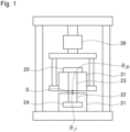
- Fig. 1 is an outline diagram of a thermal resistance measuring machine.
- thermally conductive sheet of the present invention will be described in detail with reference to the thermally conductive sheets of the first and second embodiments.
- the thermally conductive sheet according to the first embodiment of the present invention comprises a matrix formed of an organic polymer, and a fibrous filler is oriented in a thickness direction of the thermally conductive sheet.
- the thickness of the thermally conductive sheet is less than 200 ⁇ m.
- the thickness of the thermally conductive sheet exceeds 200 ⁇ m, the thermal resistance value of the thermally conductive sheet increases, so that thermal conductive properties cannot be sufficiently exerted.
- the thickness of the thermally conductive sheet is preferably less than 180 ⁇ m, and more preferably less than 170 ⁇ m.
- the lower limit of the thickness of the thermally conductive sheet is not particularly limited, but is, for example, 40 ⁇ m or more, and preferably 70 ⁇ m or more in practical use.
- the thickness of the thermally conductive sheet refers to the initial thickness measured in a state in which no load acts in the thickness direction.
- the fibrous filler is oriented in the thickness direction in the thermally conductive sheet.
- the state in which the fibrous filler is oriented in the thickness direction of the thermally conductive sheet refers to a state in which the major axis direction of the fibrous filler faces a direction in a range of within 20° from the thickness direction of the thermally conductive sheet, and when such a fibrous filler occupies a large part in the thermally conductive sheet (for example, more than 60%, preferably more than 80% based on the number of total fibrous fillers), the fibrous filler is considered to be oriented in the thickness direction.
- Such a state of orientation can be ascertained by observing a section cut along the thickness direction of the thermally conductive sheet with an electron microscope.
- D50/T is preferably 0.57 or less, and more preferably 0.55 or less.
- the upper limit of D50/T is not particularly limited, but is, for example, 0.20 or more, preferably 0.30 or more, and more preferably 0.40 or more, from the viewpoint of making the fiber length of the fibrous filler long and thermal conductive properties good.
- D50/T is preferably 0.20 or more and less than 0.58, more preferably 0.30 or more and 0.57 or less, and further preferably 0.40 or more and 0.55 or less.
- the average fiber length D50 is less than 116 ⁇ m, preferably less than 85 ⁇ m, more preferably 84 ⁇ m or less, and further preferably 73 ⁇ m or less. Setting the average fiber length D50 to the above upper limit value or less suppresses the dropping of the fibrous filler and makes it easy to reduce the thermal resistance value of the thermally conductive sheet.
- the lower limit of the average fiber length D50 of the fibrous filler is not particularly limited, but the average fiber length D50 is preferably 5 ⁇ m or more, more preferably 25 ⁇ m or more, and further preferably 35 ⁇ m or more. Setting the average fiber length D50 to the above lower limit value or more makes it easy to make the thermal conductive properties of the thermally conductive sheet good.
- the average fiber length D50 of the fibrous filler is preferably 5 ⁇ m or more and less than 116 ⁇ m, more preferably 5 ⁇ m or more and less than 85 ⁇ m, further preferably 25 ⁇ m or more and 84 ⁇ m or less, and further more preferably 35 ⁇ m or more and 73 ⁇ m or less.
- the average fiber length D90 of the fibrous filler may be, for example, less than 150 ⁇ m, preferably less than 135 ⁇ m, more preferably 132 ⁇ m or less, and further preferably 125 ⁇ m or less. Setting the average fiber length D90 to the above upper limit value or less prevents fibrous fillers which are longer than needed from being contained, so that thermal resistance value can be further reduced.
- the average fiber length D90 of the fibrous filler is preferably 10 ⁇ m or more, more preferably 50 ⁇ m or more, and further preferably 70 ⁇ m or more. Setting the average fiber length D90 to the above lower limit value or more makes it easy to make the thermal conductive properties of the thermally conductive sheet good.
- the average fiber length D90 of the fibrous filler is preferably 50 ⁇ m or more and less than 150 ⁇ m, more preferably 50 ⁇ m or more and less than 135 ⁇ m, further preferably 70 ⁇ m or more and 132 ⁇ m or less, and further more preferably 70 ⁇ m or more and 125 ⁇ m or less.
- the average fiber length D10 of the fibrous filler may be, for example, less than 85 ⁇ m, preferably 55 ⁇ m or less, and further preferably 45 ⁇ m or less. Setting the average fiber length D10 to the above upper limit value or less makes it easy to suppress the dropping of the fibrous filler, so that the thermal resistance value of the thermally conductive sheet is easily reduced.
- the average fiber length D10 of the fibrous filler is preferably 3 ⁇ m or more, more preferably 15 ⁇ m or more, and further preferably 20 ⁇ m or more. Setting the average fiber length D10 to the above lower limit value or more prevents fibrous fillers which are shorter than needed from being contained, and makes it easy to make the thermal conductive properties of the thermally conductive sheet good.
- the average fiber length D10 of the fibrous filler is preferably 3 ⁇ m or more and less than 85 ⁇ m, more preferably 15 ⁇ m or more and 55 ⁇ m or less, and further preferably 20 ⁇ m or more and 45 ⁇ m or less.
- D10, D50, and D90 of the above fibrous filler respectively mean the fiber length corresponding to the 10% cumulative frequency, the fiber length corresponding to the 50% cumulative frequency, and the fiber length corresponding to the 90% cumulative frequency.
- D10, D50, and D90 can be determined from a fiber length distribution curve in which the fibrous filler is used as the sample, the abscissa represents the fiber length, and the ordinate represents the cumulative frequency.
- the fiber length distribution curve is a fiber length distribution curve based on the number, obtained by sequential integration in order from a fibrous filler having the shortest fiber length.
- the fiber length distribution curve can be formed by measuring, for example, the fiber length of 500 or more fibrous fillers that constitute the fibrous filler using an electron microscope or an optical microscope.
- Examples of the fibrous filler used in the present invention include a carbon fiber, a metal material represented by a metal fiber and a metal oxide, boron nitride and a metal nitride, silicon carbide and a metal carbide, a metal hydroxide, and a poly-p-phenylenebenzoxazole fiber, and these fibrous fillers may be used singly, or two or more of those described above may be used together.
- a carbon fiber is preferable, and a graphitized carbon fiber is more preferable, from the viewpoint of effectively enhancing thermal conductive properties.
- a graphitized carbon fiber has a high thermal conductivity in its fiber axis direction because crystal planes of graphite run in the fiber axis direction.
- the fibrous filler is a filler having a high aspect ratio and is specifically a filler having an aspect ratio exceeding 2, and the aspect ratio is preferably 5 or more. Setting the aspect ratio to larger than 2 makes it easy to orient the fibrous filler in the thickness direction, so that the thermal conductive properties of the thermally conductive sheet are easily enhanced.
- the upper limit of the aspect ratio is not particularly limited, but is 100 in practical use.
- the aspect ratio of the fibrous filler means fiber length/diameter of fiber.
- the fibrous filler in the thermally conductive sheet is preferably 30 to 500 parts by mass, more preferably 50 to 300 parts by mass, and further preferably 100 to 250 parts by mass based on 100 parts by mass of the matrix. Setting the content of the fibrous filler to these lower limit values or more makes it easy to enhance the thermal conductive properties, and setting the content to the upper limit values or less makes it easy to properly disperse the fibrous filler in the matrix. In addition, the viscosity of the mixed composition, which will be mentioned later, is easily made proper.
- the range indicated by “to” means a range from the numerical value of the lower limit to the numerical value of the upper limit described before and after "to".
- a fibrous filler having a certain average fiber length may be contained singly, or two or more fibrous fillers each having a different average fiber length may be contained.
- D10, D50, and D90 described above are D10, D50, and D90 of the mixture of two or more fibrous fillers.
- the fibrous filler has a thermal conductivity of, though not limited to, generally 60 W/m ⁇ K or more, and preferably 400 W/m ⁇ K or more along a direction of having anisotropy (that is, major axis direction).
- the fibrous filler has a thermal conductivity of, for example, 2000 W/m ⁇ K or less although the upper limit is not particularly limited.
- the thermal conductivity can be measured by a laser flash method or a method in accordance with ASTM D5470.
- the thermally conductive sheet may contain other fillers other than the fibrous fillers described above, and for example, further preferably comprises a flake-like filler. Containing the flake-like filler can further enhance the effect of reducing the thermal resistance value due to the polishing of the thermally conductive sheet.
- the flake-like filler examples include a carbon material, a metal oxide, boron nitride and a metal nitride, silicon carbide and a metal carbide, and a metal hydroxide, and more specific examples thereof include a flake-like carbon powder, a flake-like silicon carbide powder, a flake-like aluminum nitride powder, a flake-like boron nitride powder, and a flake-like aluminum oxide powder.
- at least one selected from the group consisting of a flake-like graphite powder and a flake-like boron nitride powder is preferable, and a flake-like graphite powder is more preferable, from the viewpoint of thermal conductive properties.
- the average particle diameter (D50) is preferably 3 to 100 ⁇ m, more preferably 5 to 80 ⁇ m, and further preferably 10 to 50 ⁇ m. Setting the average particle diameter to 3 ⁇ m or more makes it easy for the fillers to come into contact with each other in the thermally conductive sheet, so that heat transmission paths are secured and the thermal conductive properties of the thermally conductive sheet are made good. On the other hand, setting the average particle diameter to 100 ⁇ m or less makes the bulkiness of the thermally conductive sheet low and makes it possible to highly fill the filler in the matrix component.
- the average particle diameter of the flake-like filler can be calculated by observing the flake-like filler with a microscope and setting the major axis as the diameter. More specifically, the major axis of arbitrary 500 or more flake-like fillers may be measured using, for example, an electron microscope or an optical microscope, and then D50 may be determined in the same manner as in the fibrous filler.
- the aspect ratio of the flake-like filler exceeds 2, and the aspect ratio is preferably 5 or more. Setting the aspect ratio to larger than 2 makes it easy to orient the flake-like filler in the thickness direction, so that the thermal conductive properties of the thermally conductive sheet are easily enhanced.
- the upper limit of the aspect ratio is not particularly limited, but is 100 in practical use.
- the aspect ratio of the flake-like filler means the length in the major axis direction/thickness of the flake-like filler.
- the flake-like carbon powder is preferably a flake-like graphite powder.
- the flake-like graphite powder has a high thermal conductivity in its in-plane direction because crystal planes of graphite run in the in-plane direction of the flake plane. Therefore, by allowing flake planes of the flake-like graphite powder to face uniformly in a predetermined direction, the thermal conductivity in a particular direction can be enhanced.
- the content of the flake-like filler in the thermally conductive sheet is preferably 1 to 100 parts by mass, more preferably 5 to 50 parts by mass, and still more preferably 10 to 40 parts by mass based on 100 parts by mass of the matrix.
- the content of the flake-like filler is these lower limit values or more, the effect of reducing the thermal resistance value due to the polishing of the thermally conductive sheet can be further enhanced, and when the content is these upper limit values or less, the viscosity of the mixed composition, which will be mentioned later, is easily made proper, so that the orientation of the flake-like filler is made good.
- graphitized carbon materials such as the graphitized carbon fiber and the flake-like graphite powder
- products obtained by graphitizing the following raw materials can be used.
- examples thereof include a condensed polycyclic hydrocarbon compound, such as naphthalene, and a condensed heterocyclic compound, such as PAN (polyacrylonitrile) or pitch, and graphitized mesophase pitch having a high degree of graphitization, polyimide, or polybenzazole in particular is preferably used.
- the pitch is oriented in the fiber axis direction due to its anisotropy in the spinning step which will be mentioned later, so that a graphitized carbon fiber having excellent thermal conductive properties in the fiber axis direction can be obtained.
- the graphitized carbon fiber obtained such that, to raw materials, treatments of spinning, infusibilization, and carbonization are conducted in sequence, and pulverization or cutting is conducted to a predetermined particle diameter, and thereafter graphitization is conducted, or the graphitized carbon fiber such that carbonization is conducted, pulverization or cutting is then conducted, and thereafter graphitization is conducted can be used.
- pulverization or cutting is conducted before graphitization, a condensation polymerization and a cyclization reaction progress easily on a surface newly exposed due to pulverization during the graphitization treatment, and therefore a graphitized carbon fiber having thermal conductive properties further improved by enhancing the degree of graphitization can be obtained.
- the thermally conductive sheet of the present invention preferably further comprises a non-anisotropic filler as the filler.
- the non-anisotropic filler is a thermally conductive filler contained in the thermally conductive sheet separately from the fibrous filler or the anisotropic filler such as the fibrous filler and the flake-like filler, and is a material which, together with the anisotropic filler, imparts thermal conductive properties to the thermally conductive sheet.
- the non-anisotropic filler has an aspect ratio of 2 or less, and preferably 1.5 or less.
- the filler having thermal conductive properties is thereby properly interposed in the space between the fibrous filler, so that the thermally conductive sheet having a high thermal conductivity is obtained.
- the aspect ratio of the anisotropic filler can be determined from major axis/minor axis of the non-anisotropic filler.
- non-anisotropic filler examples include a metal, a metal oxide, a metal nitride, a metal hydroxide, a carbon material, and an oxide, a nitride, and a carbide other than the metal oxide, the metal nitride, and a metal carbide.
- shape of the non-anisotropic filler examples include a polygonal, a spherical shape, and an indefinite-form powder.
- examples of the metal include aluminum, copper, and nickel
- examples of the metal oxide include aluminum oxide, magnesium oxide, and zinc oxide
- examples of the metal nitride include aluminum nitride.
- the metal hydroxide examples include aluminum hydroxide.
- examples of the carbon material include spheroidal graphite.
- examples of the oxide, the nitride, and the carbide other than the metal oxide, the metal nitride, and the metal carbide include quartz, boron nitride, and silicon carbide.
- the non-anisotropic filler is preferably selected from the group consisting of aluminum oxide, aluminum, zinc oxide, boron nitride, and aluminum nitride, aluminum oxide in particular is preferable from the viewpoint of filling properties and thermal conductivity, and alumina is more preferable.
- non-anisotropic filler those described above may be used singly, or two or more of those described above may be used together.
- the average particle diameter (D50) of the non-anisotropic filler is preferably 0.1 to 50 ⁇ m, more preferably 0.3 to 35 ⁇ m, and still more preferably 1 to 15 ⁇ m.
- D50 The average particle diameter of the non-anisotropic filler is preferably 0.1 to 50 ⁇ m, more preferably 0.3 to 35 ⁇ m, and still more preferably 1 to 15 ⁇ m.
- non-anisotropic filler for example, at least two non-anisotropic fillers having a different average particle diameter each other may be used as the non-anisotropic filler.
- the average particle diameter of the non-anisotropic filler can be measured by observation with an electron microscope or the like. More specifically, the particle diameters of arbitrary 500 or more non-anisotropic fillers may be measured using, for example, an electron microscope or an optical microscope, and then D50 may be determined in the same manner as in the fibrous filler.
- the content of the non-anisotropic filler is preferably in a range of 100 to 800 parts by mass, more preferably in a range of 150 to 600 parts by mass, and further preferably 180 to 400 parts by mass based on 100 parts by mass of the matrix.
- the amount of the non-anisotropic filler interposed in the space between the fibrous filler is made sufficient, and the thermal conductive properties become good.
- the content is set to 800 parts by mass or less, an effect of enhancing the thermal conductive properties corresponding to the content can be obtained.
- the thermally conductive sheet comprises a matrix formed of an organic polymer.
- the matrix is an organic polymer, such as an elastomer or a rubber, and a product formed by curing a polymer composition (curable polymer composition) in a liquid form, the polymer composition constituted by a mixed system such as the one comprising a base agent and a curing agent, may preferably be used.
- the curable polymer composition may be a composition composed of an uncrosslinked rubber and a crosslinking agent, or a composition comprising: a monomer, a prepolymer, or the like; and a curing agent or the like.
- the curing reaction may be normal-temperature curing or heat curing.
- the matrix which is formed from the curable polymer composition examples include silicone rubber.
- silicone rubber addition reaction-curable type silicone is preferably used as the matrix (curable polymer composition).
- a curable polymer composition comprising alkenyl group-containing organopolysiloxane and hydrogen organopolysiloxane may be used as the curable polymer composition.
- Suitable synthetic rubbers other than the above-described rubber can be used as the rubber, and specific examples thereof include acrylic rubber, nitrile rubber, isoprene rubber, urethane rubber, ethylene propylene rubber, styrene/butadiene rubber, butadiene rubber, fluororubber, and butyl rubber.
- the synthetic rubber may be crosslinked or left uncrosslinked (that is, uncured) in the thermally conductive sheet. Uncrosslinked rubber is used mainly in flow orientation.
- the matrix When the rubber is crosslinked (that is, cured), the matrix may be, as described above, a product obtained by curing a curable polymer composition composed of an uncrosslinked rubber which is any of these synthetic rubbers, and a crosslinking agent.
- thermoplastic elastomer such as a polyester-based thermoplastic elastomer or a polyurethane-based thermoplastic elastomer, or a heat-curable type elastomer which is formed by curing a polymer composition in a liquid form of a mixed system composed of a base agent and a curing agent
- examples of the elastomer include a polyurethane-based elastomer which is formed by curing a polymer composition comprising: a polymer having a hydroxy group; and isocyanate.
- silicone rubber, or particularly addition reaction-curable type silicone is preferably used from the viewpoint that, for example, the matrix after curing is particularly soft and filling properties of the fibrous filler, and the flake-like filler and non-anisotropic filler that are blended as necessary are good.
- the polymer composition for forming the matrix may be a polymer composition composed of a polymer compound singly, or may be a polymer composition composed of a polymer compound and a plasticizer.
- the plasticizer is suitably used when a synthetic rubber is used, and when the plasticizer is contained, the flexibility of the uncrosslinked polymer matrix can thereby be enhanced.
- the content of the matrix when expressed by a filling ratio on a volume basis (volume filling ratio), is preferably 20 to 50% by volume, and more preferably 25 to 45% by volume based on the total amount of the thermally conductive sheet.
- the content of the matrix is preferably 10 to 40% by mass, and more preferably 15 to 35% by mass based on the total amount of the thermally conductive sheet.
- a coupling agent may be used as an additive.
- the coupling agent may be blended in the mixed composition, which will be mentioned later, and the blended coupling agent may be volatilized during the production of the thermally conductive sheet.
- the coupling agent may be partially volatilized, and in this case, the remaining coupling agent may be contained in the thermally conductive sheet, or the whole coupling agent may be volatilized.
- Examples of the coupling agent include a silane coupling agent.
- Examples of the silane coupling agent include various alkoxysilane compounds such as alkylalkoxysilane.
- the amount of the coupling agent blended in the mixed composition is, for example, 1 to 50 parts by mass, and preferably 5 to 40 parts by mass based on 100 parts by mass of the polymer composition.
- various additives may further be blended in the matrix in a range where the function as the thermally conductive sheet is not impaired.
- the additive include at least one or more selected from a dispersant, a pressure-sensitive adhesive, a flame retardant, an antioxidant, a coloring agent, an anti-settling agent, and the like.
- a crosslinking accelerator, a curing accelerator, or the like that accelerates crosslinking or curing may be blended as an additive.
- the thermally conductive sheet of the present invention preferably has a thermal resistance value of 0.25°C ⁇ cm 2 /W or less, more preferably 0.2°C ⁇ cm 2 /W or less, and further preferably 0.16°C ⁇ cm 2 /W or less.
- the thermal resistance value being the above upper limit value or less improves the efficiency of the heat transmission from a heating element to a heat-dissipating element through the thermally conductive sheet, so that excellent thermal conductive properties can be obtained.
- the thermal resistance value can be obtained by the measurement method described in Examples.
- At least one surface of the thermally conductive sheet is preferably both a sliced surface and a polished surface, and both surfaces thereof are more preferably both sliced surfaces and polished surfaces.
- the viscosity of the mixed composition may be set to less than 10 Pa ⁇ s.
- shear force may be applied to the mixed composition to produce a preliminary sheet such that the fibrous filler and a flake-like filler that is blended as necessary are oriented in the plane direction, a plurality of the preliminary sheets may be laminated to produce a laminated block, and the laminated block may be used as the oriented formed body.
- the mixed composition has a relatively high viscosity such that shear force is applied when the mixed composition is stretched into a sheet-like form, and specifically, the viscosity of the mixed composition is preferably 3 to 500 Pa ⁇ s.
- a solvent is preferably blended in the mixed composition in order to obtain the viscosity.
- the mixed composition is formed into a sheet-like form (preliminary sheet) by stretching flatly while shear force is given to the mixed composition.
- the fibrous filler and the flake-like filler that is blended as necessary can be oriented in the shear direction.
- a base film may be coated with the mixed composition, for example, with an applicator for application, such as a bar coater or a doctor blade, or by extrusion forming or ejection from a nozzle, and thereafter, drying may be conducted or the mixed composition may be semi-cured as necessary.
- the thickness of the preliminary sheet is preferably set to about 50 to about 5000 ⁇ m.
- the fibrous filler and the flake-like filler that is blended as necessary are oriented in a direction along the plane direction of the sheet.
- the heating of the sheet-like formed body may be performed at, for example, 100 to 200°C, and preferably 120 to 180°C for, for example, 30 minutes to 24 hours, and preferably 1 to 6 hours.
- the sheet-like formed body obtained through the above step (B) may be used as the thermally conductive sheet as it is, and is preferably made into a thermally conductive sheet by being polished through the step (C), which will be mentioned later. Polishing makes the surface state of the sheet-like formed body good, so that the thermal resistance value is easily further reduced.
- the step (C) is a step of polishing a surface of the sheet-like formed body. Polishing the sheet-like formed body can make the sheet surface smooth while a certain amount of the anisotropic filler such as the fibrous filler is exposed on the surface. In addition, the fibrous filler can be brought into, for example, a fallen state. Thus, the surface of the thermally conductive sheet is easily closely adhered to other members, and a certain area or more of the sheet surface is easily brought into a state covered with the fibrous filler, so that the thermal resistance value is easily reduced.
- step (C) at least one surface of the sheet-like formed body obtained in the step (B) may be polished, and both surfaces of the sheet-like formed body are preferably polished.
- the polishing of the surface may be conducted using, for example, sandpaper, a polishing film, a polishing cloth, and a polishing belt.
- Sandpaper having an average grain diameter (D50) of contained abrasive grains of 0.1 to 100 ⁇ m as a characteristic of the sandpaper is preferable, and sand paper more preferably has an average grain diameter of contained abrasive grains of 1 to 60 ⁇ m.
- the particle size of abrasive grains of sandpaper for example is preferably #120 to 20000, preferably #300 to 15000, and more preferably #320 to 4000.
- polishing method a method in which, for example, polishing is conducted by allowing sandpaper to abut on the surface of the sheet-like formed body continuously in the same linear direction, polishing is conducted by reciprocating sandpaper on the surface of the thermally conductive sheet within a certain distance, polishing is conducted by rotating sandpaper in the same direction on the surface of the thermally conductive sheet, or polishing is conducted by allowing sandpaper to abut on the surface of the thermally conductive sheet in various directions can be used.
- the polishing may be conducted, for example, while the surface state is being observed, but in the case of reciprocation polishing for example, 1 to 300 times of reciprocation is preferable, more preferably 2 to 200 times, and still more preferably 3 to 50 times.
- the polishing of the surface of the sheet-like formed body may be performed by being divided into two polishing steps. For example, after the first polishing using sandpaper having a large average grain diameter of abrasive grains, the second polishing may be performed using sandpaper having a smaller average grain diameter of abrasive grains than that in the first polishing.
- thermally conductive sheet according to the second embodiment of the present invention will be described.
- the difference between the thermally conductive sheet according to the second embodiment and the thermally conductive sheet according to the first embodiment will be described.
- the thermally conductive sheet according to the second embodiment is a thermally conductive sheet comprising a matrix formed of an organic polymer, and a fibrous filler, wherein the thickness of the thermally conductive sheet is less than 200 ⁇ m, the fibrous filler is oriented in the thickness direction of the thermally conductive sheet, and the average fiber length D50 of the fibrous filler contained in the sheet is 5 ⁇ m or more and less than 85 ⁇ m.
- the average fiber length D50 in the second embodiment is preferably 25 ⁇ m or more and 84 ⁇ m or less, and more preferably 35 ⁇ m or more and 73 ⁇ m or less.
- the upper limit of the average fiber length D50 is preferably less than 85 ⁇ m; when the thickness is less than 150 ⁇ m and 125 ⁇ m or more, the upper limit of the average fiber length D50 is preferably 75 ⁇ m or less; when the thickness of the thermally conductive sheet is less than 125 ⁇ m and 100 ⁇ m or more, the upper limit of the average fiber length D50 is preferably 60 ⁇ m or less; when the thickness of the thermally conductive sheet is less than 100 ⁇ m and 75 ⁇ m or more, the upper limit of the average fiber length D50 is preferably 50 ⁇ m or less; and when the thickness of the thermally conductive sheet is less than 75 ⁇ m and 50 ⁇ m or more, the upper limit of the average fiber length D50 is preferably 40 ⁇ m or less.
- the ratio (D50/T) of the average fiber length D50 of the fibrous filler to the thickness of the thermally conductive sheet (T) may be, as in the first embodiment, less than 0.58, but does not need to be less than 0.58.
- the preferred range of the ratio (D50/T) is the same as above.
- Other detailed descriptions with respect to the fibrous filler, and detailed descriptions with respect to the filler other than the fibrous filler, matrix, additive, thermal resistance value, E hardness, aspect of the sheet surface, method for producing the thermally conductive sheet, and the like are as described in the above first embodiment, and are thus omitted.
- the thermally conductive sheet is used inside an electronic device or the like. Specifically, the thermally conductive sheet is interposed between a heating element and a heat-dissipating element, transfers heat generated at the heating element to the heat-dissipating element by heat conduction, and dissipates heat from the heat-dissipating element.
- the heating element herein include various electronic parts, such as CPU, a power amplifier, and a power source such as a battery, which are used inside an electronic device.
- Examples of the heat-dissipating element include a heat sink, a heat pipe, a heat pump, and a metal housing of an electronic device.
- the thermally conductive sheet is used in such a way that the surfaces closely adhere to a heating element and a heat-dissipating element, respectively and the thermally conductive sheet is compressed.
- the measurement method and evaluation method in the present Example are as follows.
- the average fiber lengths D10, D50, and D90 of the fibrous filler in the thermally conductive sheet were measured as described below.
- the thermally conductive sheet was immersed and dissolved in a silicone dissolving agent (KSR-1, manufactured by Kanto Chemical Co., Inc.). Then, the dissolution solution was subjected to centrifugation to separate a solid component and a liquid. The resulting solid component was further immersed in the silicone dissolving agent and subjected to centrifugation twice, and the resulting solid component was further immersed in solvent naphtha and subjected to centrifugation twice for washing, and thereafter, solvent naphtha was dried to isolate the solid component in a powder form.
- KSR-1 silicone dissolving agent
- the solid component contains a fibrous filler and a non-fibrous filler.
- an observation image image was obtained from the resulting isolate using an optical microscope ("VHX-S15" manufactured by KEYENCE CORPORATION), and thereafter, the fiber lengths of individual fibrous fillers of about 500 fibrous fillers were measured with an image analysis software WinROOF (manufactured by MITANI CORPORATION). At this time, fibrous fillers having an aspect ratio of 2 or more were only measured by needle separation with WinROOF.
- a fiber length distribution curve in which the abscissa represents the fiber length and the ordinate represents the cumulative frequency (based on the number) was obtained. The average fiber lengths D10, D50, and D90 of the fibrous filler were determined from the obtained fiber length distribution curve.
- D50 of the fibrous filler used as the raw material was determined by measuring the fiber lengths of individual fibrous fillers of about 500 fibrous fillers obtained by observing the fibrous filler before being blended in the mixed composition with the optical microscope in the same manner as above.
- D50 and the aspect ratio of the flake-like filler and the non-anisotropic filler were determined by observing about 500 particles with the optical microscope as above. In Examples, the aspect ratio refers to an average value.
- the thickness (initial thickness) of the thermally conductive sheet before measuring the thermal resistance value was measured using a thickness gage.
- the type E hardness of the thermally conductive sheet was measured based on JIS K 6253, which is a Japanese industrial standard. Specifically, measurement was performed using a type E durometer on the oriented formed bodies prepared in the respective examples.
- the thermal resistance value was measured using a thermal resistance measuring machine as shown in Fig. 1 by the method described below.
- test piece S having a size of 30 mm ⁇ 30 mm for the present test was prepared for each sample.
- Each test piece S was attached on a copper block 22 such that a measurement face has a size of 25.4 mm ⁇ 25.4 mm and side faces are covered with a thermal insulator 21, and was held between the copper block and an upper copper block 23, and load of 40 psi was applied with a load cell 26.
- the lower copper block 22 is in contact with a heater 24.
- the upper copper block 23 is covered with the thermal insulator 21 and is connected to a heat sink 25 with a fan.
- the heater 24 was heated to 80°C, and 10 minutes later when the temperature would reach an almost stationary state, the temperature of the upper copper block 23 ( ⁇ j0 ), the temperature of the lower copper block 22 ( ⁇ j1 ), and the calorific value of the heater (Q) were measured to determine the thermal resistance value of each sample from the following expression (1).
- the thickness of the thermally conductive sheet during the measurement of the thermal resistance value was also measured simultaneously with the measurement of the thermal resistance value.
- Thermal resistance ⁇ j 1 ⁇ ⁇ j 0 /Q wherein, ⁇ j1 represents the temperature of the lower copper block 22, ⁇ j0 represents the temperature of the upper copper block 23, and Q represents the calorific value.
- the following components were used as the raw materials of the thermally conductive sheet.
- sicone A agent An alkenyl group-containing organopolysiloxane as the base agent (silicone A agent), an addition reaction type organopolysiloxane including a hydrogen organopolysiloxane as the curing agent (silicone B agent)
- the following fillers were used as the fibrous filler.
- graphitized carbon fibers (1) to (8) graphitized carbon fibers having a diameter of about 10 ⁇ m were pulverized by adjusting pulverization conditions so that the above average fiber lengths can be obtained.
- Each average fiber length of each graphitized carbon fiber in the sheet after forming the sheet is as described in the column of characteristics value in Tables 1 to 10.
- a thermally conductive sheet was prepared in the same manner as in Example 1, except that the composition of the mixed composition was changed to that described in Tables 9 and 10, the thickness of the resulting thermally conductive sheet was adjusted as in Tables 9 and 10, and the resulting sheet-like formed body was not heated.
- the thermally conductive sheet of Example 1 having D50/T of less than 0.58 had a lower thermal resistance value than that of Comparative Example 4 having D50/T of 0.58 or more, although the thickness of Comparative Example 4 was thinner than that of Example 1.
- the thermally conductive sheet of Example 1 had a lower thermal resistance value than that of Comparative Examples 1 to 3 having a thickness of 200 ⁇ m or more, while having D50/T of less than 0.58. Such a tendency was also found in the comparison of Examples 2 to 9 and Comparative Examples 5 to 27 and 33 to 36.
- Comparative Examples 28 to 32 and 37 to 41 which are examples using a fibrous filler having a relatively long fiber length, had a thickness of the thermally conductive sheet of 200 ⁇ m or more or D50/T of 0.58 or more, so that the thermal resistance value was not sufficiently reduced even when D50/T was adjusted.
Landscapes
- Chemical & Material Sciences (AREA)
- Chemical Kinetics & Catalysis (AREA)
- Organic Chemistry (AREA)
- Health & Medical Sciences (AREA)
- Medicinal Chemistry (AREA)
- Polymers & Plastics (AREA)
- Engineering & Computer Science (AREA)
- Manufacturing & Machinery (AREA)
- Materials Engineering (AREA)
- Inorganic Chemistry (AREA)
- Physics & Mathematics (AREA)
- Combustion & Propulsion (AREA)
- Thermal Sciences (AREA)
- Cooling Or The Like Of Semiconductors Or Solid State Devices (AREA)
- Compositions Of Macromolecular Compounds (AREA)
- Manufacture Of Macromolecular Shaped Articles (AREA)
- Moulding By Coating Moulds (AREA)
Applications Claiming Priority (2)
| Application Number | Priority Date | Filing Date | Title |
|---|---|---|---|
| JP2022054428 | 2022-03-29 | ||
| PCT/JP2023/012651 WO2023190587A1 (fr) | 2022-03-29 | 2023-03-28 | Feuille thermoconductrice, et procédé de production d'une feuille thermoconductrice |
Publications (2)
| Publication Number | Publication Date |
|---|---|
| EP4503121A1 true EP4503121A1 (fr) | 2025-02-05 |
| EP4503121A4 EP4503121A4 (fr) | 2026-03-18 |
Family
ID=88201885
Family Applications (1)
| Application Number | Title | Priority Date | Filing Date |
|---|---|---|---|
| EP23780596.5A Pending EP4503121A4 (fr) | 2022-03-29 | 2023-03-28 | Feuille thermoconductrice, et procédé de production d?une feuille thermoconductrice |
Country Status (7)
| Country | Link |
|---|---|
| US (1) | US20250092207A1 (fr) |
| EP (1) | EP4503121A4 (fr) |
| JP (1) | JPWO2023190587A1 (fr) |
| KR (1) | KR20240167780A (fr) |
| CN (1) | CN118541792A (fr) |
| TW (1) | TW202346529A (fr) |
| WO (1) | WO2023190587A1 (fr) |
Family Cites Families (6)
| Publication number | Priority date | Publication date | Assignee | Title |
|---|---|---|---|---|
| JPS6082777U (ja) | 1983-11-11 | 1985-06-07 | ソニー株式会社 | テ−プカセツト |
| JP2017135137A (ja) | 2016-01-25 | 2017-08-03 | 東洋紡株式会社 | 絶縁高熱伝導性シート、およびその製法、および積層体 |
| EP3419399B1 (fr) * | 2016-04-11 | 2020-08-26 | Sekisui Polymatech Co., Ltd. | Feuille conductrice de la chaleur |
| JP6753745B2 (ja) * | 2016-09-12 | 2020-09-09 | デクセリアルズ株式会社 | 熱伝導シート、及び半導体装置 |
| US20190300771A1 (en) * | 2016-09-28 | 2019-10-03 | Teijin Limited | Heat dissipation sheet |
| US20230365766A1 (en) * | 2020-09-30 | 2023-11-16 | Sekisui Polymatech Co., Ltd. | Thermally conductive sheet |
-
2023
- 2023-03-28 KR KR1020247022952A patent/KR20240167780A/ko active Pending
- 2023-03-28 JP JP2024512606A patent/JPWO2023190587A1/ja active Pending
- 2023-03-28 WO PCT/JP2023/012651 patent/WO2023190587A1/fr not_active Ceased
- 2023-03-28 EP EP23780596.5A patent/EP4503121A4/fr active Pending
- 2023-03-28 US US18/727,520 patent/US20250092207A1/en active Pending
- 2023-03-28 CN CN202380016875.8A patent/CN118541792A/zh active Pending
- 2023-03-29 TW TW112112016A patent/TW202346529A/zh unknown
Also Published As
| Publication number | Publication date |
|---|---|
| TW202346529A (zh) | 2023-12-01 |
| KR20240167780A (ko) | 2024-11-28 |
| EP4503121A4 (fr) | 2026-03-18 |
| JPWO2023190587A1 (fr) | 2023-10-05 |
| CN118541792A (zh) | 2024-08-23 |
| WO2023190587A1 (fr) | 2023-10-05 |
| US20250092207A1 (en) | 2025-03-20 |
Similar Documents
| Publication | Publication Date | Title |
|---|---|---|
| CN108781524B (zh) | 导热片 | |
| EP3860321B1 (fr) | Feuille thermoconductrice | |
| EP3848960B1 (fr) | Feuille thermoconductrice | |
| EP3813103B1 (fr) | Feuille thermoconductrice | |
| EP3813104B1 (fr) | Feuille thermoconductrice | |
| US20230323181A1 (en) | Heat-conductive sheet, method for attaching same and method for producing same | |
| EP3981829B1 (fr) | Feuille thermoconductrice et son procédé de production | |
| EP4223829A1 (fr) | Feuille thermiquement conductrice | |
| EP4503121A1 (fr) | Feuille thermoconductrice, et procédé de production d?une feuille thermoconductrice | |
| WO2022210419A1 (fr) | Procédé de fabrication de feuille thermoconductrice | |
| EP4503120A1 (fr) | Feuille thermoconductrice | |
| EP4693396A1 (fr) | Feuille thermoconductrice et son procédé de fabrication | |
| EP4503119A1 (fr) | Feuille thermoconductrice, son procédé d'installation et son procédé de fabrication |
Legal Events
| Date | Code | Title | Description |
|---|---|---|---|
| STAA | Information on the status of an ep patent application or granted ep patent |
Free format text: STATUS: THE INTERNATIONAL PUBLICATION HAS BEEN MADE |
|
| PUAI | Public reference made under article 153(3) epc to a published international application that has entered the european phase |
Free format text: ORIGINAL CODE: 0009012 |
|
| STAA | Information on the status of an ep patent application or granted ep patent |
Free format text: STATUS: REQUEST FOR EXAMINATION WAS MADE |
|
| 17P | Request for examination filed |
Effective date: 20240709 |
|
| AK | Designated contracting states |
Kind code of ref document: A1 Designated state(s): AL AT BE BG CH CY CZ DE DK EE ES FI FR GB GR HR HU IE IS IT LI LT LU LV MC ME MK MT NL NO PL PT RO RS SE SI SK SM TR |
|
| DAV | Request for validation of the european patent (deleted) | ||
| DAX | Request for extension of the european patent (deleted) | ||
| REG | Reference to a national code |
Ref country code: DE Ref legal event code: R079 Free format text: PREVIOUS MAIN CLASS: H01L0023373000 Ipc: C08K0003040000 |
|
| A4 | Supplementary search report drawn up and despatched |
Effective date: 20260213 |
|
| RIC1 | Information provided on ipc code assigned before grant |
Ipc: C08K 3/04 20060101AFI20260209BHEP Ipc: C08K 3/08 20060101ALI20260209BHEP Ipc: C08K 3/22 20060101ALI20260209BHEP Ipc: C08K 5/5419 20060101ALI20260209BHEP Ipc: C08K 7/06 20060101ALI20260209BHEP Ipc: C08J 5/04 20060101ALI20260209BHEP Ipc: C08J 5/18 20060101ALI20260209BHEP Ipc: C08L 83/04 20060101ALI20260209BHEP Ipc: C08L 83/08 20060101ALI20260209BHEP Ipc: C09K 5/14 20060101ALI20260209BHEP Ipc: H10W 40/25 20260101ALN20260209BHEP Ipc: H10W 40/70 20260101ALN20260209BHEP |