EP4503165A1 - Sekundärbatterie und elektrische vorrichtung - Google Patents
Sekundärbatterie und elektrische vorrichtung Download PDFInfo
- Publication number
- EP4503165A1 EP4503165A1 EP22960039.0A EP22960039A EP4503165A1 EP 4503165 A1 EP4503165 A1 EP 4503165A1 EP 22960039 A EP22960039 A EP 22960039A EP 4503165 A1 EP4503165 A1 EP 4503165A1
- Authority
- EP
- European Patent Office
- Prior art keywords
- film layer
- active material
- optionally
- negative active
- negative
- Prior art date
- Legal status (The legal status is an assumption and is not a legal conclusion. Google has not performed a legal analysis and makes no representation as to the accuracy of the status listed.)
- Pending
Links
Images
Classifications
-
- H—ELECTRICITY
- H01—ELECTRIC ELEMENTS
- H01M—PROCESSES OR MEANS, e.g. BATTERIES, FOR THE DIRECT CONVERSION OF CHEMICAL ENERGY INTO ELECTRICAL ENERGY
- H01M4/00—Electrodes
- H01M4/02—Electrodes composed of, or comprising, active material
- H01M4/13—Electrodes for accumulators with non-aqueous electrolyte, e.g. for lithium-accumulators; Processes of manufacture thereof
-
- H—ELECTRICITY
- H01—ELECTRIC ELEMENTS
- H01M—PROCESSES OR MEANS, e.g. BATTERIES, FOR THE DIRECT CONVERSION OF CHEMICAL ENERGY INTO ELECTRICAL ENERGY
- H01M4/00—Electrodes
- H01M4/02—Electrodes composed of, or comprising, active material
- H01M4/36—Selection of substances as active materials, active masses, active liquids
- H01M4/58—Selection of substances as active materials, active masses, active liquids of inorganic compounds other than oxides or hydroxides, e.g. sulfides, selenides, tellurides, halogenides or LiCoFy; of polyanionic structures, e.g. phosphates, silicates or borates
- H01M4/583—Carbonaceous material, e.g. graphite-intercalation compounds or CFx
- H01M4/587—Carbonaceous material, e.g. graphite-intercalation compounds or CFx for inserting or intercalating light metals
-
- H—ELECTRICITY
- H01—ELECTRIC ELEMENTS
- H01M—PROCESSES OR MEANS, e.g. BATTERIES, FOR THE DIRECT CONVERSION OF CHEMICAL ENERGY INTO ELECTRICAL ENERGY
- H01M10/00—Secondary cells; Manufacture thereof
- H01M10/05—Accumulators with non-aqueous electrolyte
- H01M10/052—Li-accumulators
- H01M10/0525—Rocking-chair batteries, i.e. batteries with lithium insertion or intercalation in both electrodes; Lithium-ion batteries
-
- H—ELECTRICITY
- H01—ELECTRIC ELEMENTS
- H01M—PROCESSES OR MEANS, e.g. BATTERIES, FOR THE DIRECT CONVERSION OF CHEMICAL ENERGY INTO ELECTRICAL ENERGY
- H01M4/00—Electrodes
- H01M4/02—Electrodes composed of, or comprising, active material
- H01M4/13—Electrodes for accumulators with non-aqueous electrolyte, e.g. for lithium-accumulators; Processes of manufacture thereof
- H01M4/133—Electrodes based on carbonaceous material, e.g. graphite-intercalation compounds or CFx
-
- H—ELECTRICITY
- H01—ELECTRIC ELEMENTS
- H01M—PROCESSES OR MEANS, e.g. BATTERIES, FOR THE DIRECT CONVERSION OF CHEMICAL ENERGY INTO ELECTRICAL ENERGY
- H01M4/00—Electrodes
- H01M4/02—Electrodes composed of, or comprising, active material
- H01M4/13—Electrodes for accumulators with non-aqueous electrolyte, e.g. for lithium-accumulators; Processes of manufacture thereof
- H01M4/134—Electrodes based on metals, Si or alloys
-
- H—ELECTRICITY
- H01—ELECTRIC ELEMENTS
- H01M—PROCESSES OR MEANS, e.g. BATTERIES, FOR THE DIRECT CONVERSION OF CHEMICAL ENERGY INTO ELECTRICAL ENERGY
- H01M4/00—Electrodes
- H01M4/02—Electrodes composed of, or comprising, active material
- H01M4/13—Electrodes for accumulators with non-aqueous electrolyte, e.g. for lithium-accumulators; Processes of manufacture thereof
- H01M4/139—Processes of manufacture
- H01M4/1393—Processes of manufacture of electrodes based on carbonaceous material, e.g. graphite-intercalation compounds or CFx
-
- H—ELECTRICITY
- H01—ELECTRIC ELEMENTS
- H01M—PROCESSES OR MEANS, e.g. BATTERIES, FOR THE DIRECT CONVERSION OF CHEMICAL ENERGY INTO ELECTRICAL ENERGY
- H01M4/00—Electrodes
- H01M4/02—Electrodes composed of, or comprising, active material
- H01M4/36—Selection of substances as active materials, active masses, active liquids
-
- H—ELECTRICITY
- H01—ELECTRIC ELEMENTS
- H01M—PROCESSES OR MEANS, e.g. BATTERIES, FOR THE DIRECT CONVERSION OF CHEMICAL ENERGY INTO ELECTRICAL ENERGY
- H01M4/00—Electrodes
- H01M4/02—Electrodes composed of, or comprising, active material
- H01M4/36—Selection of substances as active materials, active masses, active liquids
- H01M4/362—Composites
- H01M4/364—Composites as mixtures
-
- H—ELECTRICITY
- H01—ELECTRIC ELEMENTS
- H01M—PROCESSES OR MEANS, e.g. BATTERIES, FOR THE DIRECT CONVERSION OF CHEMICAL ENERGY INTO ELECTRICAL ENERGY
- H01M4/00—Electrodes
- H01M4/02—Electrodes composed of, or comprising, active material
- H01M4/36—Selection of substances as active materials, active masses, active liquids
- H01M4/362—Composites
- H01M4/366—Composites as layered products
-
- H—ELECTRICITY
- H01—ELECTRIC ELEMENTS
- H01M—PROCESSES OR MEANS, e.g. BATTERIES, FOR THE DIRECT CONVERSION OF CHEMICAL ENERGY INTO ELECTRICAL ENERGY
- H01M4/00—Electrodes
- H01M4/02—Electrodes composed of, or comprising, active material
- H01M4/62—Selection of inactive substances as ingredients for active masses, e.g. binders, fillers
-
- H—ELECTRICITY
- H01—ELECTRIC ELEMENTS
- H01M—PROCESSES OR MEANS, e.g. BATTERIES, FOR THE DIRECT CONVERSION OF CHEMICAL ENERGY INTO ELECTRICAL ENERGY
- H01M4/00—Electrodes
- H01M4/02—Electrodes composed of, or comprising, active material
- H01M2004/021—Physical characteristics, e.g. porosity, surface area
-
- H—ELECTRICITY
- H01—ELECTRIC ELEMENTS
- H01M—PROCESSES OR MEANS, e.g. BATTERIES, FOR THE DIRECT CONVERSION OF CHEMICAL ENERGY INTO ELECTRICAL ENERGY
- H01M4/00—Electrodes
- H01M4/02—Electrodes composed of, or comprising, active material
- H01M2004/026—Electrodes composed of, or comprising, active material characterised by the polarity
- H01M2004/027—Negative electrodes
-
- H—ELECTRICITY
- H01—ELECTRIC ELEMENTS
- H01M—PROCESSES OR MEANS, e.g. BATTERIES, FOR THE DIRECT CONVERSION OF CHEMICAL ENERGY INTO ELECTRICAL ENERGY
- H01M4/00—Electrodes
- H01M4/02—Electrodes composed of, or comprising, active material
- H01M4/36—Selection of substances as active materials, active masses, active liquids
- H01M4/38—Selection of substances as active materials, active masses, active liquids of elements or alloys
- H01M4/386—Silicon or alloys based on silicon
-
- Y—GENERAL TAGGING OF NEW TECHNOLOGICAL DEVELOPMENTS; GENERAL TAGGING OF CROSS-SECTIONAL TECHNOLOGIES SPANNING OVER SEVERAL SECTIONS OF THE IPC; TECHNICAL SUBJECTS COVERED BY FORMER USPC CROSS-REFERENCE ART COLLECTIONS [XRACs] AND DIGESTS
- Y02—TECHNOLOGIES OR APPLICATIONS FOR MITIGATION OR ADAPTATION AGAINST CLIMATE CHANGE
- Y02E—REDUCTION OF GREENHOUSE GAS [GHG] EMISSIONS, RELATED TO ENERGY GENERATION, TRANSMISSION OR DISTRIBUTION
- Y02E60/00—Enabling technologies; Technologies with a potential or indirect contribution to GHG emissions mitigation
- Y02E60/10—Energy storage using batteries
Definitions
- a lithium secondary battery characterized by a high energy density, a high operating potential, a long cycle life, and a low self-discharge rate has been commercially available and widely used.
- This application provides a secondary battery and an electrical device to further improve the cycle performance of the secondary battery.
- a first aspect of this application provides a secondary battery, including a current collector and a negative film layer.
- the negative film layer includes: a first film layer, disposed on at least one surface of the current collector, where the first film layer includes a first negative active material; a second film layer, disposed on a surface of the first film layer, where the surface is away from the current collector, and the second film layer includes a second negative active material.
- a volume distribution diameter Dv 50 of the first negative active material is greater than a volume distribution diameter Dv 50 of the second negative active material, and a powder compaction density of the first negative active material is greater than the powder compaction density of the second negative active material under a same pressure.
- this application causes the two film layers to compensate for each other in terms of porosity and pore size, thereby balancing electrolyte infiltration performance of the two film layers to prevent the upper second film layer from being over-lithiation or over-sodiation, effectively avoiding precipitation of metal on the second film layer, improving the cycle performance of the secondary battery, and increasing the lifespan of the secondary battery.
- the volume distribution diameter Dv 50 of the first negative active material is denoted as D1
- the volume distribution diameter Dv 50 of the second negative active material is denoted as D2, satisfying: 1 ⁇ D1/D2 ⁇ 3.0, and optionally 1.3 ⁇ D1/D2 ⁇ 2.8. This further improves the electrolyte infiltration performance of the two film layers, and further improves the cycle performance of the secondary battery.
- the powder compaction density of the first negative active material under a pressure of 30000 N is denoted as PD1
- the powder compaction density of the second negative active material under a pressure of 30000 N is denoted as PD2, satisfying: 1 ⁇ PD1/PD2 ⁇ 2.0, optionally 1.03 ⁇ PD1/PD2 ⁇ 1.5, and further optionally 1.05 ⁇ PD1/PD2 ⁇ 1.3. This further improves the cycle performance of the secondary battery.
- the volume distribution diameter Dv 50 of the first negative electrode material is 5 ⁇ m to 30 ⁇ m, optionally 7 ⁇ m to 28 ⁇ m, and further optionally 8 ⁇ m to 26 ⁇ m; and/or the volume distribution diameter Dv 50 of the second negative electrode material is 2 ⁇ m to 20 ⁇ m, optionally 3 ⁇ m to 15 ⁇ m, and further optionally 6 ⁇ m to 15 ⁇ m. This further improves the cycle performance of the secondary battery.
- the powder compaction density PD1 of the first negative active material under a pressure of 30000 N is 1.2 g/cm 3 to 2.5 g/cm 3 , and optionally 1.5 g/cm 3 to 2.0 g/cm 3 .
- the powder compaction density PD2 of the second negative active material under a pressure of 30000 N is 1.0 g/cm 3 to 2.0 g/cm 3 , optionally 1.2 g/cm 3 to 1.8 g/cm 3 , further optionally 1.2 g/cm 3 to 1.65 g/cm 3 , and further optionally 1.55 g/cm 3 to 1.6 g/cm 3 . This further improves the cycle performance of the secondary battery.
- the first negative active material further satisfies one or more of the following conditions (1) to (4): (1) a volume distribution diameter Dv 10 of the first negative active material is 4 ⁇ m to 15 ⁇ m, and optionally 5 ⁇ m to 11 ⁇ m; (2) a volume distribution diameter Dv 90 of the first negative active material is less than or equal to 45 ⁇ m, and preferably 15 ⁇ m to 35 ⁇ m; (3) a specific surface area SSA of the first negative active material is less than or equal to 3.0 m 2 /g, and optionally is 0.7 m 2 /g to 2.5 m 2 /g; (3) the first negative active material includes a carbon-based material, and optionally the carbon-based material includes at least one of artificial graphite, natural graphite, soft carbon, or hard carbon; and (4) the first negative active material includes a carbon-based material and a silicon-based material, optionally a mass percent of the silicon-based material in the first film layer is less than or equal to 75%, and is further preferably 0%
- the second negative active material further satisfies one or more of the following conditions (I) to (V): (I) a volume distribution diameter Dv 10 of the second negative electrode material is 3 ⁇ m to 10 ⁇ m, and optionally 3 ⁇ m to 8 ⁇ m; (II) a volume distribution diameter Dv 90 of the second negative electrode material is less than or equal to 35 ⁇ m, and preferably 10 ⁇ m to 25 ⁇ m; (III) a specific surface area SSA of the second negative active material is less than or equal to 2.0 m 2 /g, and optionally is 0.5 m 2 /g to 1.6 m 2 /g; (IV) the second negative active material includes a carbon-based material, and optionally the carbon-based material includes at least one of artificial graphite, natural graphite, soft carbon, or hard carbon; and (V) the second negative active material includes a carbon-based material and a silicon-based material, optionally a mass percent of the silicon-based material in the first film layer is less than
- the first negative active material and the second negative active material each independently include artificial graphite and/or natural graphite.
- the specific surface area of natural graphite is larger. Therefore, the natural graphite may be used in a larger amount in the second negative active material.
- a compaction density of the first film layer is denoted as PD1'
- a compaction density of the second film layer is denoted as PD2', satisfying: 1 ⁇ PD17PD2' ⁇ 2.0, and optionally 1.03 ⁇ PD1'/PD2' ⁇ 1.5.
- the cycle performance of the secondary battery can be improved more reliably by using the specified ratio of the compaction density.
- a compaction density of the negative film layer is 1.35 g/cm 3 to 2.5 g/cm 3 , optionally 1.50 g/cm 3 to 2.5 g/cm 3 ;
- a compaction density PD1' of the first film layer is 1.2 g/cm 3 to 2.5 g/cm 3 , and optionally 1.5 g/cm 3 to 2.0 g/cm 3 ;
- a compaction density PD2' of the second film layer is 1.0 g/cm 3 to 2.0 g/cm 3 , and optionally 1.2 g/cm 3 to 1.65 g/cm 3 .
- the cycle performance of the secondary battery can be improved more reliably by using the above compaction density.
- the first film layer and the second film layer each independently include a binder.
- a content of the binder in the first film layer is greater than a content of the binder in the second film layer.
- a mass percent of the binder in the first film layer is denoted as A
- a mass percent of the binder in the second film layer is denoted as B, satisfying: 1 ⁇ A/B ⁇ 3.5, optionally 1 ⁇ A/B ⁇ 2.2, and further optionally 1 ⁇ A/B ⁇ 1.9.
- the binder is usually a polymer insulation substance.
- the binders in the first film layer and the second film layer are both prone to float to the superficial layer as the solvent volatilizes. Therefore, in view of the characteristics of the binder floating up, the amount of binder in the first film layer is set to be larger than the amount of binder in the second film layer, thereby not only ensuring the kinetic properties of the first negative electrode material in the second film layer, but also effectively alleviating the problem of de-bonding of the active material caused by the floating of the binder in the second film layer.
- Dv 50 of the second negative electrode material is less than Dv 50 of the first negative electrode material, thereby increasing the tortuosity of particle interstices of the second negative electrode material of the second film layer, and in turn, more effectively suppressing the floating of the binder during preparation of the second film layer.
- the binder in the first film layer is more than the binder in the second film layer, and is more prone to float to a junction between the two film layers, thereby improving the peel strength between the two film layers.
- a thickness of the first film layer is denoted as h1
- a thickness of the second film layer is denoted as h2, satisfying: 3/7 ⁇ h1/h2 ⁇ 7/3, and optionally 2/3 ⁇ h1/h2 ⁇ 3/2.
- the coating mass can be used to adjust the thickness of the film layer.
- the film layers formed with the same coating mass also vary in thickness due to a different compaction density.
- the thickness of a negative film layer on a single side of the current collector is 30 ⁇ m to 150 ⁇ m.
- the negative electrode plate further includes a primer.
- the primer is disposed on at least one surface of the current collector.
- the first negative film layer is disposed on a surface of the primer, the surface being away from the current collector. The primer effectively increases the bonding area and bonding strength between the negative film layer and the current collector, and reduces the impedance of the negative electrode body.
- the first film layer and the second film layer each independently include a binder.
- a mass percent of the binder in the first film layer is denoted as A
- a mass percent of the binder in the second film layer is denoted as B, satisfying: 1 ⁇ A/B ⁇ 3.5, optionally 1.2 ⁇ A/B ⁇ 2.5, and further optionally 1.2 ⁇ A/B ⁇ 1.9, thereby reducing the difference of the binder content between the two film layers, and reducing the dosage of the binder in the first film layer.
- a thickness of the primer is denoted as h0, and a thickness of the first film layer is denoted as h1, satisfying: h1/h0 ⁇ 25;
- the thickness of the primer is controlled by using the above relational expression, so that the energy density of the negative electrode plate is increased maximally on the basis of sufficiently exerting the bonding strength between the negative film layer and the current collector.
- the thickness of the primer is less than or equal to 5 ⁇ m, and further, less than or equal to 3 ⁇ m, so as to further increase the energy density of the negative electrode plate.
- a second aspect of this application provides an electrical device, including a secondary battery.
- the secondary battery is selected from the secondary batteries disclosed above.
- the electrical device containing the secondary battery of this application achieves a long lifespan and good cycle performance.
- a “range” disclosed herein is defined in the form of a lower limit and an upper limit.
- a given range is defined by a lower limit and an upper limit selected. The selected lower and upper limits define the boundaries of a particular range.
- a range so defined may be inclusive or exclusive of the end values, and a lower limit of one range may be arbitrarily combined with an upper limit of another range to form a range. For example, if a range of 60 to 120 and a range of 80 to 110 are set out for a given parameter, it is expectable that such ranges may be understood as 60 to 110 and 80 to 120.
- a numerical range "a to b" is a brief representation of a combination of any real numbers between a and b inclusive, where both a and b are real numbers.
- a numerical range "0 to 5" herein means all real numbers recited between 0 and 5 inclusive, and the expression "0 to 5" is just a brief representation of a combination of such numbers.
- a statement that a parameter is an integer greater than or equal to 2 is equivalent to a disclosure that the parameter is an integer such as 2, 3, 4, 5, 6, 7, 8, 9, 10, 11, 12, and so on.
- any embodiments and optional embodiments hereof may be combined with each other to form a new technical solution.
- any technical features and optional technical features hereof may be combined with each other to form a new technical solution.
- steps described herein may be performed in sequence or at random, and preferably in sequence.
- the method includes steps (a) and (b) indicates that the method may include steps (a) and (b) performed in sequence, or steps (b) and (a) performed in sequence.
- the method may further include step (c) indicates that step (c) may be added into the method in any order.
- the method may include steps (a), (b), and (c), or may include steps (a), (c), and (b), or may include steps (c), (a), and (b), and so on.
- the term "or” is inclusive.
- the expression “A or B” means “A alone, B alone, or both A and B”. More specifically, all and any of the following conditions satisfy the condition "A or B”: A is true (or existent) and B is false (or absent); A is false (or absent) and B is true (or existent); and, both A and B are true (or existent).
- a secondary battery also known as a rechargeable battery or storage battery, is a battery that is reusable after an active material in the battery is activated by charging the battery that has been discharged.
- the secondary battery of this application includes a negative electrode plate.
- the negative electrode plate includes a current collector and a negative film layer.
- a secondary battery further includes a positive electrode plate, a separator, and an electrolyte solution.
- active ions such as lithium ions
- the separator Disposed between the positive electrode plate and the negative electrode plate, the separator primarily serves to prevent a short circuit between the positive electrode plate and the negative electrode plate while allowing passage of active ions.
- the electrolyte solution is located between the positive electrode plate and the negative electrode plate, and primarily serves to conduct the active ions.
- the thickness of the negative film layer is usually increased, or a double-layer film is employed.
- the increase in the thickness of the negative film layer impairs the cycle performance of the battery, and the double-layer film increases the difficulty of infiltrating the two layers of the double-layer film and also impairs the cycle performance of the battery.
- the secondary battery disclosed herein includes a negative electrode plate.
- the negative electrode plate includes a current collector and a negative film layer.
- the negative film layer includes a first film layer and a second film layer.
- the first film layer is disposed on at least one surface of the current collector.
- the first film layer includes a first negative active material.
- the second film layer is disposed on a surface of the first film layer, where the surface is away from the current collector.
- the second film layer includes a second negative active material.
- a volume distribution diameter Dv 50 of the first negative active material is greater than a volume distribution diameter Dv 50 of the second negative active material, and a powder compaction density of the first negative active material is greater than the powder compaction density of the second negative active material under a same pressure.
- this application causes the two film layers to compensate each other in terms of porosity and pore size, thereby balancing electrolyte infiltration performance of the two film layers to prevent the upper second film layer from being over-lithiation or over-sodiation, effectively avoiding precipitation of metal on the second film layer, improving the cycle performance of the secondary battery, and increasing the lifespan of the secondary battery.
- the first negative active material is softer and more compressible than the second negative active material. Therefore, even if the volume distribution diameter Dv 50 of the first negative active material is greater than the volume distribution diameter Dv 50 of the second negative active material, the powder compaction density of the first negative active material can be greater than the powder compaction density of the second negative active material under a same pressure.
- the porosity of the first film layer is low.
- the first film layer is balanced by the first negative electrode material with a relatively large Dv 50 particle diameter. Large pores exist between large particles of the first negative electrode material, thereby improving the electrolyte infiltration performance of the first film layer in a case of a high compaction density.
- Due to the relatively high compaction density of the second negative active material the porosity of the corresponding second film layer is relatively high.
- the second film layer is balanced by the material with a relatively small Dv 50 value that forms small pores.
- the two negative active materials collaborate with each other to achieve the purpose of balancing the electrolyte infiltration effect between the upper film layer and the lower film layer.
- the volume distribution diameter Dv 50 of the first negative active material is denoted as D1
- the volume distribution diameter Dv 50 of the second negative active material is denoted as D2, satisfying: 1 ⁇ D1/D2 ⁇ 3.0, and optionally 1.3 ⁇ D1/D2 ⁇ 2.8.
- the powder compaction density of the first negative active material under a pressure of 30000 N is denoted as PD1
- the powder compaction density of the second negative active material under a pressure of 30000 N is denoted as PD2, satisfying: 1 ⁇ PD1/PD2 ⁇ 2.0, optionally 1.03 ⁇ PD1/PD2 ⁇ 1.5, and further optionally 1.05 ⁇ PD1/PD2 ⁇ 1.3.
- Dv 50 of the first negative active material falls within 5 ⁇ m to 30 ⁇ m, optionally 7 ⁇ m to 28 ⁇ m, further optionally 8 ⁇ m to 26 ⁇ m, or 7 ⁇ m to 20 ⁇ m, or 10 ⁇ m to 20 ⁇ m, or 10 ⁇ m to 15 ⁇ m.
- Dv 50 may be 5 ⁇ m, 7 ⁇ m, 8 ⁇ m, 10 ⁇ m, 12 ⁇ m, 15 ⁇ m, 17 ⁇ m, 20 ⁇ m, 23 ⁇ m, 25 ⁇ m, 26 ⁇ m, 28 ⁇ m, or 30 ⁇ m.
- Dv 50 of the second negative active material falls within 2 ⁇ m to 20 ⁇ m, optionally 3 ⁇ m to 15 ⁇ m, and further optionally 6 ⁇ m to 15 ⁇ m, or 6 ⁇ m to 10 ⁇ m.
- Dv 50 of the second negative active material may be 2 ⁇ m, 3 ⁇ m, 4 ⁇ m, 5 ⁇ m, 6 ⁇ m, 9 ⁇ m, 10 ⁇ m, 11 ⁇ m, 12 ⁇ m, 13 ⁇ m, 14 ⁇ m, 15 ⁇ m, 18 ⁇ m, or 20 ⁇ m.
- the powder compaction density PD1 of the first negative active material under a pressure of 30000 N is 1.2 g/cm 3 to 2.5 g/cm 3 , optionally 1.5 g/cm 3 to 2.0 g/cm 3 , and further optionally, 1.65 g/cm 3 to 2.0 g/cm 3 .
- the powder compaction density PD2 of the second negative active material under a pressure of 30000 N is 1.0 g/cm 3 to 2.0 g/cm 3 , optionally 1.2 g/cm 3 to 1.8 g/cm 3 , further optionally 1.2 g/cm 3 to 1.65 g/cm 3 , and further optionally 1.55 g/cm 3 to 1.6 g/cm 3 .
- the first negative active material and the second negative active material are used to collaborate with each other to further improve the electrolyte infiltration performance of the two film layers, and in turn, further improve the cycle performance of the secondary battery.
- the relatively high compaction density is used to increase the energy density of the negative electrode plate.
- the first negative active material further satisfies one or more of the following conditions (1) to (4): (1) a volume distribution diameter Dv 10 of the first negative active material is 4 ⁇ m to 15 ⁇ m, and optionally 5 ⁇ m to 11 ⁇ m; (2) a volume distribution diameter Dv 90 of the first negative active material is less than or equal to 45 ⁇ m, and preferably 15 ⁇ m to 35 ⁇ m; (3) a specific surface area SSA of the first negative active material is less than or equal to 3.0 m 2 /g, and optionally is 0.7 m 2 /g to 2.5 m 2 /g; (3) the first negative active material includes a carbon-based material, and optionally the carbon-based material includes at least one of artificial graphite, natural graphite, soft carbon, or hard carbon; and (4) the first negative active material includes a carbon-based material and a silicon-based material, optionally a mass percent of the silicon-based material in the first film layer is less than or equal to 75%, and is further preferably
- the second negative active material further satisfies one or more of the following conditions (I) to (V): (I) a volume distribution diameter Dv 10 of the second negative electrode material is 3 ⁇ m to 10 ⁇ m, and optionally 3 ⁇ m to 8 ⁇ m; (II) a volume distribution diameter Dv 90 of the second negative electrode material is less than or equal to 35 ⁇ m, and preferably 10 ⁇ m to 25 ⁇ m; (III) a specific surface area SSA of the second negative active material is less than or equal to 2.0 m 2 /g, and optionally is 0.5 m 2 /g to 1.6 m 2 /g; (IV) the second negative active material includes a carbon-based material, and optionally the carbon-based material includes at least one of artificial graphite, natural graphite, soft carbon, or hard carbon; and (V) the second negative active material includes a carbon-based material and a silicon-based material, optionally a mass percent of the silicon-based material in the first film layer is less
- the material with a small particle diameter can fill the pores between the particles of the material with a large particle diameter, thereby enabling more flexible adjustment of the compaction density of the film layer.
- the compaction density difference between the first film layer and the second film layer that are formed under the same pressure is easier to control, and the compensation effect for the porosity and pore size of the two film layers is more noticeable.
- the difference in Dv 10 between the first negative electrode material and the second negative electrode material can be relatively small.
- the difference in the particle size between the first negative electrode material and the second negative electrode material mainly depends on Dv 50 and Dv 90 .
- the problem of deteriorated cycle performance caused by mechanical structure damage of the silicon-based material due to an excessive mass percent of the material can be effectively suppressed by improving the specific capacity of the battery by use of a silicon-based material and by controlling the mass percent of the silicon-based material.
- Dv 10 , D v50 , and Dv 90 of the negative active material bear the meanings well known in the art, and may be measured by a method known in the art.
- the volume median diameter may be tested by using a laser particle size analyzer (such as Malvern Mastersizer 3000) with reference to the standard GB/T 19077.1-2016.
- Dv 10 and Dv 50 are as follows:
- the powder compaction density of the negative active material bears a meaning well known in the art, and may be tested by a method known in the art.
- the carbon-based material may include at least one of: artificial graphite, natural graphite, soft carbon, hard carbon, or the like.
- the silicon-based material may be at least one selected from simple-substance silicon, a silicon-oxygen compound, a silicon-carbon composite, a silicon-nitrogen composite, and a silicon alloy.
- the first negative electrode material and the second negative electrode material each independently include artificial graphite and/or natural graphite. Generally, the specific surface area of natural graphite is larger. Therefore, the natural graphite may be used in a larger amount in the second negative electrode material.
- a specific surface area SSA of the second negative active material is greater than or equal to a specific surface area SSA of the first negative active material.
- the larger the specific surface area of the second negative active material the easier it is to achieve lithiation to improve the kinetics of the second negative electrode material and further improve the performance of the electrode plate.
- the specific surface area (Specific surface area, SSA) of the negative active material bears a meaning well known in the art, and may be tested by a method known in the art.
- the specific surface area is measured by using a nitrogen adsorption-based specific surface area analysis method, and is calculated by a Brunauer Emmett Teller (BET) method.
- BET Brunauer Emmett Teller
- the nitrogen adsorption-based specific surface area analysis may be performed by using a Tri Star 3020 specific surface area and pore size analyzer manufactured by the US-based Micromeritics Company.
- a compaction density of the first film layer is denoted as PD 1'
- a compaction density of the second film layer is denoted as PD2', satisfying: 1 ⁇ PD17PD2' ⁇ 2.0, and optionally 1.03 ⁇ PD1'/PD2' ⁇ 1.5.
- the cycle performance of the secondary battery can be improved more reliably by using the specified ratio of the compaction density.
- a compaction density of the negative film layer is 1.35 g/cm 3 to 2.5 g/cm 3 , optionally 1.50 g/cm 3 to 2.5 g/cm 3 ; a compaction density PD1' of the first film layer is 1.2 g/cm 3 to 2.5 g/cm 3 , and optionally 1.5 g/cm 3 to 2.0 g/cm 3 ; and a compaction density PD2' of the second film layer is 1.0 g/cm 3 to 2.0 g/cm 3 , and optionally 1.2 g/cm 3 to 1.65 g/cm 3 .
- the cycle performance of the secondary battery can be improved more reliably by using the above compaction density.
- the compaction density of the film layer is a compaction density of a corresponding film layer in a fresh electrode plate.
- the test method of the compaction density of the first film layer and the second film layer may be obtained with reference to the following steps (1) to (9):
- the first film layer and the second film layer each independently include a binder.
- a content of the binder in the first film layer is greater than a content of the binder in the second film layer.
- a mass percent of the binder in the first film layer is denoted as A
- a mass percent of the binder in the second film layer is denoted as B, satisfying: 1 ⁇ A/B ⁇ 1.2.
- the binder is usually a polymer insulation substance. In a drying process after coating, the binders in the first film layer and the second film layer are both prone to float to the superficial layer as the solvent volatilizes.
- the amount of binder in the first film layer is set to be larger than the amount of binder in the second film layer, thereby not only ensuring the kinetic properties of the first negative electrode material in the second film layer, but also effectively alleviating the problem of de-bonding of the active material caused by the floating of the binder in the second film layer.
- Dv 50 of the second negative active material is less than Dv 50 of the first negative active material, thereby increasing the tortuosity of particle interstices of the second negative active material of the second film layer, and in turn, more effectively suppressing the floating of the binder during preparation of the second film layer.
- the binder in the first film layer is more than the binder in the second film layer, and is more prone to float to a junction between the two film layers, thereby improving the peel strength between the two film layers.
- the binder content in the slurry forming the first film layer is greater than the binder content in the slurry forming the second film layer. After floating, the binder content in the first film layer can keep greater than the binder content in the second film layer.
- the binder is prone to float up, the floating does not cause a fundamental change in the binder content in the first film layer and the second film layer. Therefore, the binder content in the two film layers is adjusted on the basis of the conventional binder content setting to achieve the relative proportion of the binder specified above.
- the thermal decomposition mass of the binder is measured by differential thermal and thermogravimetric analysis.
- the binder may be at least one selected from styrenebutadiene rubber (SBR), polyacrylic acid (PAA), polyacrylic acid sodium (PAAS), polyacrylamide (PAM), polyvinyl alcohol (PVA), sodium alginate (SA), polymethyl acrylic acid (PMAA), and carboxymethyl chitosan (CMCS).
- SBR styrenebutadiene rubber
- PAA polyacrylic acid
- PAAS polyacrylic acid sodium
- PAM polyacrylamide
- PVA polyvinyl alcohol
- SA sodium alginate
- PMAA polymethyl acrylic acid
- CMCS carboxymethyl chitosan
- the negative film layer further optionally includes a conductive agent.
- the conductive agent may be at least one selected from superconductive carbon, acetylene black, carbon black, Ketjen black, carbon dots, carbon nanotubes, graphene, or carbon nanofibers.
- the negative film layer further optionally includes other agents, such as a thickener (for example, sodium carboxymethyl cellulose (CMC-Na)).
- a thickener for example, sodium carboxymethyl cellulose (CMC-Na)
- a thickness of the first film layer is denoted as h1
- a thickness of the second film layer is denoted as h2, satisfying: 3/7 ⁇ h1/h2 ⁇ 7/3, and optionally 2/3 ⁇ h1/h2 ⁇ 3/2.
- the coating mass can be used to adjust the thickness of the film layer.
- the film layers formed with the same coating mass also vary in thickness due to a different compaction density.
- the thickness of the negative film layer on a single side of the current collector is 30 ⁇ m to 150 ⁇ m.
- the negative electrode plate further includes a primer.
- the primer is disposed on at least one surface of the current collector.
- the first negative film layer is disposed on a surface of the primer, the surface being away from the current collector. The primer effectively increases the bonding area and bonding strength between the negative film layer and the current collector, and reduces the impedance of the negative electrode body.
- the first film layer and the second film layer each independently include a binder.
- a mass percent of the binder in the first film layer is denoted as A
- a mass percent of the binder in the second film layer is denoted as B, satisfying: 1 ⁇ A/B ⁇ 3.5, optionally 1.2 ⁇ A/B ⁇ 2.5, and further optionally 1.2 ⁇ A/B ⁇ 1.9, thereby reducing the difference of the binder content between the two film layers, and reducing the dosage of the binder in the first film layer.
- a thickness of the primer is denoted as h0
- a thickness of the first film layer is denoted as h1, satisfying: h1/h0 ⁇ 25.
- the thickness of the primer is controlled by using the above relational expression, so that the energy density of the negative electrode plate is increased maximally on the basis of sufficiently exerting the bonding strength between the negative film layer and the current collector.
- the thickness of the primer is less than or equal to 5 ⁇ m, and further, less than or equal to 3 ⁇ m, so as to further increase the energy density of the negative electrode plate.
- the thickness of the negative film layer may be measured with a ten-thousandth micrometer, for example, a Mitutoyo293-100 ten-thousandth micrometer with accuracy of 0.1 ⁇ m.
- the thicknesses of the primer, the first film layer, and the second film layer may be tested by using a scanning electron microscope (such as ZEISS Sigma300).
- An exemplary test method is: First, cutting the negative electrode plate into a specimen of a specified size (for example, 2 cm ⁇ 2 cm), and fixing the specimen of the negative electrode plate onto a specimen holder by using paraffin; and subsequently, loading the specimen holder onto the specimen rack and locking the rack, powering on an argon ion cross-section polisher (model: IB-19500CP, for example) and performing vacuumizing (at a pressure of 10 -4 Pa, for example), setting the argon flow rate (such as 0.15 MPa), voltage (such as 8 KV), and polishing duration (such as 2 hours), and adjusting the specimen holder to a wobble mode to start polishing.
- an argon ion cross-section polisher model: IB-19500CP, for example
- vacuumizing at a pressure of 10 -4 Pa, for example
- a plurality of (for example, 10) different regions may be selected randomly from a specimen for scanning.
- the thicknesses of the primer, the first film layer, and the second film layer in a specified test region are measured at a specified magnification (such as 500 ⁇ ).
- the test results of a plurality of test regions are averaged out, and the average values are the thickness of the primer, the first film layer, and the second film layer respectively.
- the negative current collector may be metal foil or a composite current collector.
- the metal foil may be a copper foil.
- the composite current collector may include a polymer material substrate and a metal layer formed on at least one surface of the polymer material substrate.
- the composite current collector may be formed by overlaying the polymer material substrate with a metal material (for example, copper, copper alloy, nickel, nickel alloy, titanium, titanium alloy, silver, and silver alloy).
- the polymer material substrate may be, for example, polypropylene (PP), polyethylene terephthalate (PET), polybutylene terephthalate (PBT), polystyrene (PS), or polyethylene (PE).
- the negative electrode plate may be prepared according to the following method: dispersing the ingredients of the negative electrode plate such as the negative active material, the conductive agent, and the binder and any other ingredients in a solvent (such as deionized water) to form a negative electrode slurry, coating a negative current collector with the negative electrode slurry, and performing steps such as drying and cold calendering to obtain the negative electrode plate.
- a solvent such as deionized water
- the sampling may be performed according to the following steps:
- the position of the junction between the first negative film layer and the second negative film layer may be determined by using an optical microscope or a scanning electron microscope during the sampling.
- the parameter ranges of the primer and the negative film layer (such as thicknesses of the primer and the negative film layer) specified herein mean the parameter ranges of a film layer on a single side of the current collector.
- the technical solution is considered to fall within the protection scope of this application as long as the parameters of the primer or negative film layer on any one surface of the negative current collector satisfy this application.
- the thickness range of the negative film layer mentioned in this application means a parameter of the film layer compacted by cold pressing and ready for assembling a battery.
- a positive electrode plate generally includes a positive current collector and a positive film layer that overlays at least one surface of the positive current collector.
- the positive film layer includes a positive active material.
- the positive current collector includes two surfaces opposite to each other in a thickness direction of the positive current collector.
- the positive film layer is disposed on either or both of the two opposite surfaces of the positive current collector.
- the positive current collector may be a metal foil or a composite current collector.
- the metal foil may be an aluminum foil.
- the composite current collector may include a polymer material substrate and a metal layer formed on at least one surface of the polymer material substrate.
- the composite current collector may be formed by overlaying the polymer material substrate with a metal material (for example, aluminum, aluminum alloy, nickel, nickel alloy, titanium, titanium alloy, silver, and silver alloy).
- the polymer material substrate may be, for example, polypropylene (PP), polyethylene terephthalate (PET), polybutylene terephthalate (PBT), polystyrene (PS), or polyethylene (PE).
- the positive active material may be a positive active material that is well known for use in a battery in the art.
- the positive active material may include at least one of the following materials: olivine-structured lithium-containing phosphate, lithium transition metal oxide, and a modified compound thereof.
- this application is not limited to such materials, and other conventional materials usable as a positive active material of a battery may be used instead. Of such positive active materials, one may be used alone, or at least two may be used in combination.
- lithium transition metal oxide may include, but without being limited to, at least one of lithium cobalt oxide (such as LiCoO 2 ), lithium nickel oxide (such as LiNiO 2 ), lithium manganese oxide (such as LiMnO 2 and LiMn 2 O 4 ), lithium nickel cobalt oxide, lithium manganese cobalt oxide, lithium nickel manganese oxide, lithium nickel cobalt manganese oxide (such as LiNi 1/3 Co 1/3 Mn 1/3 O 2 (briefly referred to as NCM333), LiNi 0.5 Co 0.2 Mn 0.3 O 2 (briefly referred to as NCM523), LiNi 0.5 Co 0.25 Mn 0.25 O 2 (briefly referred to as NCM211), LiNi 0.6 Co 0.2 Mn 0.2 O 2 (briefly referred to as NCM622), LiNi 0.8 Co 0.1 Mn 0.1 O 2 (briefly referred to as NCM811)), lithium nickel cobalt aluminum oxide (such as LiNi 0.85 Co 0.15 Al 0.05 O 2 ), or
- Examples of the olivine-structured lithium-containing phosphate may include, but without being limited to, at least one of lithium iron phosphate (such as LiFePO 4 (briefly referred to as LFP)), a composite of lithium iron phosphate and carbon, lithium manganese phosphate (such as LiMnPO 4 ), a composite of lithium manganese phosphate and carbon, lithium manganese iron phosphate, or a composite of lithium manganese iron phosphate and carbon.
- lithium iron phosphate such as LiFePO 4 (briefly referred to as LFP)
- LiMnPO 4 lithium manganese phosphate
- LiMnPO 4 lithium manganese phosphate and carbon
- lithium manganese iron phosphate such as LiMnPO 4
- the positive film layer further optionally includes a binder.
- the binder may include at least one of polyvinylidene difluoride (PVDF), polytetrafluoroethylene (PTFE), poly(vinylidene fluoride-co-tetrafluoroethylene-co-propylene), poly (vinylidene fluoride-co-hexafluoropropylene-co-tetrafluoroethylene), poly(tetrafluoroethylene-co-hexafluoropropylene), or fluorinated acrylate resin.
- PVDF polyvinylidene difluoride
- PTFE polytetrafluoroethylene
- PTFE poly(vinylidene fluoride-co-tetrafluoroethylene-co-propylene)
- the positive film layer further optionally includes a conductive agent.
- the conductive agent may include at least one of superconductive carbon, acetylene black, carbon black, Ketjen black, carbon dots, carbon nanotubes, graphene, or carbon nanofibers.
- the positive electrode plate may be prepared according to the following method: dispersing the ingredients of the positive electrode plate such as the positive active material, the conductive agent, the binder, and any other ingredients into a solvent (such as N-methyl-pyrrolidone) to form a positive electrode slurry, coating a positive current collector with the positive electrode slurry, and performing steps such as drying and cold pressing to obtain the positive electrode plate.
- a solvent such as N-methyl-pyrrolidone
- the electrolyte serves to conduct ions between the positive electrode plate and the negative electrode plate.
- the type of the electrolyte is not particularly limited in this application, and may be selected as required.
- the electrolyte may be in a liquid state or gel state, or all solid state.
- the electrolyte is in a liquid state and includes an electrolyte salt and a solvent.
- the electrolyte salt may be at least one selected from lithium hexafluorophosphate, lithium tetrafluoroborate, lithium perchlorate, lithium hexafluoroarsenate, lithium bisfluorosulfonimide, lithium bistrifluoromethanesulfonimide, lithium trifluoromethanesulfonate, lithium difluorophosphate, lithium difluoro(oxalato)borate, lithium bis(oxalato)borate, lithium difluoro(bisoxalato)phosphate, and lithium tetrafluoro(oxalato)phosphate.
- the solvent may be at least one selected from ethylene carbonate, propylene carbonate, ethyl methyl carbonate, diethyl carbonate, dimethyl carbonate, dipropyl carbonate, methyl propyl carbonate, ethylene propyl carbonate, butylene carbonate, fluoroethylene carbonate, methyl formate, methyl acetate, ethyl acetate, propyl acetate, methyl propionate, ethyl propionate, propyl propionate, methyl butyrate, ethyl butyrate, 1,4-butyrolactone, sulfolane, methyl sulfonyl methane, ethyl methyl sulfone, and (ethylsulfonyl)ethane.
- the electrolyte solution further optionally includes an additive.
- the additive may include a negative film-forming additive or a positive film-forming additive.
- the additive may further include an additive capable of improving some performance of the battery, for example, an additive for improving overcharge performance of the battery, or an additive for improving high- or low-temperature performance of the battery.
- the secondary battery further includes a separator.
- the type of the separator is not particularly limited in this application, and may be any well-known porous separator that is highly stable both chemically and mechanically.
- the separator may be made of a material that is at least one selected from glass fiber, non-woven fabric, polyethylene, polypropylene, and polyvinylidene difluoride.
- the separator may be a single-layer film or a multilayer composite film, without being particularly limited.
- materials in different layers may be identical or different, without being particularly limited.
- the positive electrode plate, the negative electrode plate, and the separator may be made into an electrode assembly by winding or stacking.
- the secondary battery may include an outer package.
- the outer package may be configured to package the electrode assembly and the electrolyte.
- the outer package of the secondary battery may be a hard shell such as a hard plastic shell, an aluminum shell, a steel shell, or the like.
- the outer package of the secondary battery may be a soft package such as a pouch-type soft package.
- the soft package may be made of plastic such as polypropylene, polybutylene terephthalate, or polybutylene succinate.
- the shape of the secondary battery is not particularly limited in this application, and may be cylindrical, prismatic or any other shape.
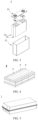
- FIG. 2 shows a prismatic secondary battery 5 as an example.
- FIG. 4 shows a battery module 4 as an example.
- a plurality of secondary batteries 5 may be arranged sequentially along a length direction of the battery module 4.
- the secondary batteries may be arranged in any other manner.
- the plurality of secondary batteries 5 may be fixed by a fastener.
- the battery module 4 may further include a shell that provides an accommodation space.
- the plurality of secondary batteries 5 are accommodated in the accommodation space.
- the battery module may be assembled to form a battery pack.
- the battery pack may include one or more battery modules, and the specific number of battery modules in a battery pack may be selected by a person skilled in the art depending on practical applications and capacity of the battery pack.
- FIG. 5 and FIG. 6 show a battery pack 1 as an example.
- the battery pack 1 may include a battery box and a plurality of battery modules 4 disposed in the battery box.
- the battery box includes an upper box 2 and a lower box 3.
- the upper box 2 fits the lower box 3 to form a closed space for accommodating the battery modules 4.
- the plurality of battery modules 4 may be arranged in the battery box in any manner.
- the electrical device includes at least one of the secondary battery, the battery module, or the battery pack according to this application.
- the secondary battery, the battery module, or the battery pack may be used as a power supply of the electrical device, or used as an energy storage unit of the electrical device.
- the electrical device may include, but without being limited to, a mobile device (such as a mobile phone or a laptop computer), an electric vehicle (such as a battery electric vehicle, a hybrid electric vehicle, a plug-in hybrid electric vehicle, an electric bicycle, an electric scooter, an electric golf cart, or an electric truck), an electric train, a ship, a satellite system, or an energy storage system.
- the secondary battery, the battery module, or the battery pack may be selected for use in the electrical device according to practical requirements of the electrical device.
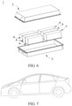
- FIG. 7 shows an electrical device as an example.
- the electrical device may be a battery electric vehicle, a hybrid electric vehicle, a plug-in hybrid electric vehicle, or the like.
- the electrical device may adopt a battery pack or a battery module in order to meet the requirements of the electrical device on a high power and a high energy density of the secondary battery.
- NCM811 as a positive active material
- conductive carbon black (Super P) as a conductive agent
- PVDF polyvinylidene difluoride
- NMP N-methyl-pyrrolidone
- the areal density of the positive film layer on one side of the positive current collector is 0.250 g/1540.25 mm 2
- the compaction density is 3.45 g/cm 3 .
- the first step is to prepare a first negative electrode slurry: Stirring and mixing well artificial graphite as a first negative active material, SBR as a binder, sodium carboxymethyl cellulose (CMC-Na) as a thickener, and conductive carbon black (Super P) as a conductive agent at a mass ratio of 96.5: 1.8: 1.0: 0.7 in a deionized water solvent to prepare a first negative electrode slurry.
- the powder compaction density of the artificial graphite under a pressure of 30000 N is 1.75 g/cm 3
- the volume distribution diameter Dv 50 is 8 ⁇ m
- Dv 10 is 6.5 ⁇ m
- Dv 90 is 34.3 ⁇ m
- the specific surface area is 1.98 m 2 /g.
- the second step is to prepare a second negative electrode slurry: Stirring and mixing well artificial graphite as a second negative active material, SBR as a binder, sodium carboxymethyl cellulose (CMC-Na) as a thickener, and conductive carbon black (Super P) as a conductive agent at a mass ratio of 96.8: 1.5: 1.0: 0.7 in a deionized water solvent to prepare a second negative electrode slurry.
- the powder compaction density of the artificial graphite under a pressure of 30000 N is 1.60 g/cm 3 , the volume distribution diameter Dv 50 is 6 ⁇ m, Dv 10 is 5.6 ⁇ m, Dv 90 is 19.4 ⁇ m, and the specific surface area is 1.08 m 2 /g.
- the third step is to simultaneously extrude the first negative electrode slurry and the second negative electrode slurry to form a wet film through a two-chamber applicator.
- the first negative electrode slurry is applied on both surfaces of negative current collector copper foil to form a first negative film layer.
- the second negative electrode slurry is applied on the first negative film layer to form a second negative film layer.
- the fourth step is to bake and dry the wet film in different temperature zones of the oven, and then cold-press the film to obtain a negative film layer with a desired compaction density, and then perform steps such as slitting and cutting to obtain a negative electrode plate.
- a thickness ratio between the first negative film layer and the second negative film layer is 5: 5.
- the areal density of the negative film layer is 0.180 g/1540.25 mm 2 .
- the compaction density of the negative film layer is 1.7 g/cm 3 .
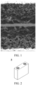
- FIG. 1 shows a scanning electron microscope image of a partial cross-section of the negative electrode plate.
- the first film layer is close to the current collector, and the second film layer is close to the surface.
- the pore size of the first film layer is relatively large but the porosity of the first film layer is relatively low.
- the pore size of the second film layer is relatively small but the porosity of the second film layer is relatively high. Therefore, the pore characteristics of the two film layers are complementary to each other so that the two film layers are infiltrated by the electrolyte solution to a similar effect, thereby improving the cycle capacity retention rate of the battery.
- EC ethylene carbonate
- EMC ethyl methyl carbonate
- DEC diethyl carbonate
- Electrode assembly Stacking the positive electrode plate, the separator, and the negative electrode plate sequentially, and winding them to obtain an electrode assembly; placing the electrode assembly into an outer package, injecting the electrolyte solution, and performing steps such as packaging, standing, chemical formation, and aging to obtain a secondary battery.
- the secondary batteries prepared in each embodiment and each comparative embodiment are charged and discharged for a first time at 25 °C according to the following procedure: Leaving a secondary battery to stand static at a temperature of 25 °C for 30 minutes, and then charging the battery at a constant current of 1 C until the voltage reaches 4.25 V Continuing to charge the battery at a constant voltage until the current drops to or below 0.05 C, and then discharging the battery at a constant current of 1 C until the voltage reaches 2.8 V, and recording the first-cycle discharge capacity C 1 .
- N th -cycle capacity retention rate (N th -cycle discharge capacity/first-cycle discharge capacity) ⁇ 100%.
- D1, D2, PD 1, and PD2 all affect the capacity retention rate.
- the two negative active materials collaborate with each other and the parameter values fall within the preferred ranges specified herein, the effect in improving the capacity retention rate is noticeable.
- the capacity retention rate can be improved by adjusting the particle size distribution of the materials.
- Embodiment 3 Embodiment 5, and Embodiment 6, after Dv 50 of the first negative active material is determined, with the decrease of Dv 50 of the second negative active material, the pores in the film layer formed by the two negative active materials are more complementary, and improve the capacity retention rate more effectively.
- Embodiment 2 and Embodiment 5 when Dv 50 of the second negative active material is similar, with the increase of Dv 50 of the first negative active material, the pores in the film layer formed by the two negative active materials are more complementary, and improve the capacity retention rate more effectively.
Landscapes
- Chemical & Material Sciences (AREA)
- Chemical Kinetics & Catalysis (AREA)
- Electrochemistry (AREA)
- General Chemical & Material Sciences (AREA)
- Engineering & Computer Science (AREA)
- Materials Engineering (AREA)
- Composite Materials (AREA)
- Manufacturing & Machinery (AREA)
- Inorganic Chemistry (AREA)
- Battery Electrode And Active Subsutance (AREA)
Applications Claiming Priority (1)
| Application Number | Priority Date | Filing Date | Title |
|---|---|---|---|
| PCT/CN2022/122628 WO2024065402A1 (zh) | 2022-09-29 | 2022-09-29 | 一种二次电池及用电装置 |
Publications (2)
| Publication Number | Publication Date |
|---|---|
| EP4503165A1 true EP4503165A1 (de) | 2025-02-05 |
| EP4503165A4 EP4503165A4 (de) | 2025-09-10 |
Family
ID=90475329
Family Applications (1)
| Application Number | Title | Priority Date | Filing Date |
|---|---|---|---|
| EP22960039.0A Pending EP4503165A4 (de) | 2022-09-29 | 2022-09-29 | Sekundärbatterie und elektrische vorrichtung |
Country Status (4)
| Country | Link |
|---|---|
| US (1) | US20250079436A1 (de) |
| EP (1) | EP4503165A4 (de) |
| CN (1) | CN118648128A (de) |
| WO (1) | WO2024065402A1 (de) |
Families Citing this family (3)
| Publication number | Priority date | Publication date | Assignee | Title |
|---|---|---|---|---|
| CN119812186A (zh) * | 2024-09-11 | 2025-04-11 | 比亚迪股份有限公司 | 负极极片和二次电池 |
| CN119069644A (zh) * | 2024-11-05 | 2024-12-03 | 宁德时代新能源科技股份有限公司 | 锂离子二次电池、用于制备其的组件、制备方法和用电装置 |
| CN119153758A (zh) * | 2024-11-12 | 2024-12-17 | 宁德时代新能源科技股份有限公司 | 电池单体、电池装置以及用电装置 |
Family Cites Families (8)
| Publication number | Priority date | Publication date | Assignee | Title |
|---|---|---|---|---|
| ES2926653T3 (es) * | 2019-12-06 | 2022-10-27 | Contemporary Amperex Technology Co Ltd | Batería secundaria y aparato que incluye la batería secundaria |
| CN113036298B (zh) * | 2019-12-06 | 2022-02-11 | 宁德时代新能源科技股份有限公司 | 负极极片及含有它的二次电池、装置 |
| WO2021217576A1 (zh) * | 2020-04-30 | 2021-11-04 | 宁德时代新能源科技股份有限公司 | 二次电池、其制备方法及含有该二次电池的装置 |
| WO2021217639A1 (zh) * | 2020-04-30 | 2021-11-04 | 宁德时代新能源科技股份有限公司 | 二次电池、其制备方法和含有该二次电池的装置 |
| CN111916667B (zh) * | 2020-07-27 | 2021-07-16 | 珠海冠宇电池股份有限公司 | 一种负极片及包括该负极片的锂离子电池 |
| CN112820852B (zh) * | 2020-12-30 | 2022-04-15 | 珠海冠宇电池股份有限公司 | 一种负极片和锂离子电池 |
| CN214956955U (zh) * | 2021-05-17 | 2021-11-30 | 珠海冠宇电池股份有限公司 | 一种负极片及电池 |
| CN113745451A (zh) * | 2021-08-30 | 2021-12-03 | 湖北亿纬动力有限公司 | 一种负极片、负极片的制备方法及锂离子电池 |
-
2022
- 2022-09-29 WO PCT/CN2022/122628 patent/WO2024065402A1/zh not_active Ceased
- 2022-09-29 EP EP22960039.0A patent/EP4503165A4/de active Pending
- 2022-09-29 CN CN202280086097.5A patent/CN118648128A/zh active Pending
-
2024
- 2024-11-15 US US18/949,142 patent/US20250079436A1/en active Pending
Also Published As
| Publication number | Publication date |
|---|---|
| US20250079436A1 (en) | 2025-03-06 |
| WO2024065402A1 (zh) | 2024-04-04 |
| CN118648128A (zh) | 2024-09-13 |
| EP4503165A4 (de) | 2025-09-10 |
Similar Documents
| Publication | Publication Date | Title |
|---|---|---|
| US11631852B2 (en) | Secondary battery, preparation method thereof, and battery module, battery pack, and apparatus associated therewith | |
| EP3900085B1 (de) | Anodenmaterial, anode und elektrochemische vorrichtung mit anodenmaterial | |
| EP3926713B1 (de) | Sekundärbatterie, verfahren zu ihrer herstellung und diese sekundärbatterie enthaltende vorrichtung | |
| EP4597630A1 (de) | Negativelektrodenaktivmaterial, negativelektrodenfolie damit, elektrochemische vorrichtung und elektrische vorrichtung | |
| EP4170755A1 (de) | Positivelektrodenmaterial, positivelektrodenpolteil, lithiumsekundärbatterie, batteriemodul, batteriepack und vorrichtung | |
| CN113875047B (zh) | 二次电池及其制备方法、含有该二次电池的装置 | |
| EP4047711A1 (de) | Batteriemodul, batteriepack, elektronisches gerät sowie verfahren zur herstellung eines batteriemoduls und herstellungsverfahren | |
| US20250079436A1 (en) | Secondary battery and electrical device | |
| EP2597706B1 (de) | Lithiumionensekundärbatterie | |
| EP4239717A1 (de) | Positivelektrodenplatte, sekundärbatterie, batteriemodul, batteriepack und elektrische vorrichtung | |
| EP3958352B1 (de) | Sekundärbatterie, herstellungsverfahren dafür und vorrichtung enthaltend die sekundärbatterie | |
| EP4175039A1 (de) | Negativelektrodenpolteil und sekundärbatterie, batteriepack, batteriemodul und elektrische vorrichtung | |
| EP4451377A1 (de) | Sekundärbatterie, batteriemodul, batteriepack und elektrische vorrichtung | |
| JP2024504525A (ja) | 二次電池及びそれを含む電力消費装置 | |
| EP4219396A1 (de) | Kohlenstoffbasiertes leitfähiges mittel, sekundärbatterie und elektrische vorrichtung | |
| EP4503173A1 (de) | Negativelektrodenplatte und herstellungsverfahren dafür, sekundärbatterie, batteriemodul, batteriepack und elektrische vorrichtung | |
| EP4287331A1 (de) | Sekundärbatterie, batteriemodul, batteriepack und elektrische vorrichtung | |
| US20250046786A1 (en) | Secondary battery, manufacturing method therefor, and device containing secondary battery | |
| CN115832187B (zh) | 电极及其制备方法、二次电池、电池模块、电池包和用电装置 | |
| EP4654281A1 (de) | Sekundärbatterie und elektrische vorrichtung | |
| EP4550477A1 (de) | Lithiumergänzungspaste, positivelektrodenpaste, sekundärbatterie, herstellungsverfahren für sekundärbatterie und elektrische vorrichtung | |
| EP4535449A1 (de) | Sekundärbatterie und elektronische vorrichtung | |
| US20220199986A1 (en) | Negative electrode material, electrochemical device containing same, and electronic device | |
| EP4611061A1 (de) | Sekundärbatterie und elektrische vorrichtung | |
| EP4386889A1 (de) | Negativelektrodenaktivsubstanz und herstellungsverfahren dafür sowie sekundärbatterie und elektrische vorrichtung damit |
Legal Events
| Date | Code | Title | Description |
|---|---|---|---|
| STAA | Information on the status of an ep patent application or granted ep patent |
Free format text: STATUS: THE INTERNATIONAL PUBLICATION HAS BEEN MADE |
|
| PUAI | Public reference made under article 153(3) epc to a published international application that has entered the european phase |
Free format text: ORIGINAL CODE: 0009012 |
|
| STAA | Information on the status of an ep patent application or granted ep patent |
Free format text: STATUS: REQUEST FOR EXAMINATION WAS MADE |
|
| 17P | Request for examination filed |
Effective date: 20241028 |
|
| AK | Designated contracting states |
Kind code of ref document: A1 Designated state(s): AL AT BE BG CH CY CZ DE DK EE ES FI FR GB GR HR HU IE IS IT LI LT LU LV MC MK MT NL NO PL PT RO RS SE SI SK SM TR |
|
| A4 | Supplementary search report drawn up and despatched |
Effective date: 20250808 |
|
| RIC1 | Information provided on ipc code assigned before grant |
Ipc: H01M 4/13 20100101AFI20250804BHEP Ipc: H01M 4/133 20100101ALI20250804BHEP Ipc: H01M 4/134 20100101ALI20250804BHEP Ipc: H01M 4/1393 20100101ALI20250804BHEP Ipc: H01M 4/36 20060101ALI20250804BHEP Ipc: H01M 4/587 20100101ALI20250804BHEP Ipc: H01M 10/0525 20100101ALI20250804BHEP Ipc: H01M 4/02 20060101ALI20250804BHEP |
|
| DAV | Request for validation of the european patent (deleted) | ||
| DAX | Request for extension of the european patent (deleted) |