EP4503217A1 - Dispositif de fabrication d'ensemble électrode et son procédé de fabrication - Google Patents
Dispositif de fabrication d'ensemble électrode et son procédé de fabrication Download PDFInfo
- Publication number
- EP4503217A1 EP4503217A1 EP23863449.7A EP23863449A EP4503217A1 EP 4503217 A1 EP4503217 A1 EP 4503217A1 EP 23863449 A EP23863449 A EP 23863449A EP 4503217 A1 EP4503217 A1 EP 4503217A1
- Authority
- EP
- European Patent Office
- Prior art keywords
- electrode
- separator
- assembly
- unit
- buffer table
- Prior art date
- Legal status (The legal status is an assumption and is not a legal conclusion. Google has not performed a legal analysis and makes no representation as to the accuracy of the status listed.)
- Pending
Links
Images



Classifications
-
- H—ELECTRICITY
- H01—ELECTRIC ELEMENTS
- H01M—PROCESSES OR MEANS, e.g. BATTERIES, FOR THE DIRECT CONVERSION OF CHEMICAL ENERGY INTO ELECTRICAL ENERGY
- H01M50/00—Constructional details or processes of manufacture of the non-active parts of electrochemical cells other than fuel cells, e.g. hybrid cells
- H01M50/40—Separators; Membranes; Diaphragms; Spacing elements inside cells
- H01M50/46—Separators, membranes or diaphragms characterised by their combination with electrodes
-
- H—ELECTRICITY
- H01—ELECTRIC ELEMENTS
- H01M—PROCESSES OR MEANS, e.g. BATTERIES, FOR THE DIRECT CONVERSION OF CHEMICAL ENERGY INTO ELECTRICAL ENERGY
- H01M10/00—Secondary cells; Manufacture thereof
- H01M10/04—Construction or manufacture in general
- H01M10/0404—Machines for assembling batteries
-
- H—ELECTRICITY
- H01—ELECTRIC ELEMENTS
- H01M—PROCESSES OR MEANS, e.g. BATTERIES, FOR THE DIRECT CONVERSION OF CHEMICAL ENERGY INTO ELECTRICAL ENERGY
- H01M10/00—Secondary cells; Manufacture thereof
- H01M10/04—Construction or manufacture in general
- H01M10/0413—Large-sized flat cells or batteries for motive or stationary systems with plate-like electrodes
-
- H—ELECTRICITY
- H01—ELECTRIC ELEMENTS
- H01M—PROCESSES OR MEANS, e.g. BATTERIES, FOR THE DIRECT CONVERSION OF CHEMICAL ENERGY INTO ELECTRICAL ENERGY
- H01M10/00—Secondary cells; Manufacture thereof
- H01M10/04—Construction or manufacture in general
- H01M10/0436—Small-sized flat cells or batteries for portable equipment
-
- H—ELECTRICITY
- H01—ELECTRIC ELEMENTS
- H01M—PROCESSES OR MEANS, e.g. BATTERIES, FOR THE DIRECT CONVERSION OF CHEMICAL ENERGY INTO ELECTRICAL ENERGY
- H01M10/00—Secondary cells; Manufacture thereof
- H01M10/04—Construction or manufacture in general
- H01M10/0459—Cells or batteries with folded separator between plate-like electrodes
-
- H—ELECTRICITY
- H01—ELECTRIC ELEMENTS
- H01M—PROCESSES OR MEANS, e.g. BATTERIES, FOR THE DIRECT CONVERSION OF CHEMICAL ENERGY INTO ELECTRICAL ENERGY
- H01M50/00—Constructional details or processes of manufacture of the non-active parts of electrochemical cells other than fuel cells, e.g. hybrid cells
- H01M50/40—Separators; Membranes; Diaphragms; Spacing elements inside cells
- H01M50/403—Manufacturing processes of separators, membranes or diaphragms
-
- Y—GENERAL TAGGING OF NEW TECHNOLOGICAL DEVELOPMENTS; GENERAL TAGGING OF CROSS-SECTIONAL TECHNOLOGIES SPANNING OVER SEVERAL SECTIONS OF THE IPC; TECHNICAL SUBJECTS COVERED BY FORMER USPC CROSS-REFERENCE ART COLLECTIONS [XRACs] AND DIGESTS
- Y02—TECHNOLOGIES OR APPLICATIONS FOR MITIGATION OR ADAPTATION AGAINST CLIMATE CHANGE
- Y02E—REDUCTION OF GREENHOUSE GAS [GHG] EMISSIONS, RELATED TO ENERGY GENERATION, TRANSMISSION OR DISTRIBUTION
- Y02E60/00—Enabling technologies; Technologies with a potential or indirect contribution to GHG emissions mitigation
- Y02E60/10—Energy storage using batteries
-
- Y—GENERAL TAGGING OF NEW TECHNOLOGICAL DEVELOPMENTS; GENERAL TAGGING OF CROSS-SECTIONAL TECHNOLOGIES SPANNING OVER SEVERAL SECTIONS OF THE IPC; TECHNICAL SUBJECTS COVERED BY FORMER USPC CROSS-REFERENCE ART COLLECTIONS [XRACs] AND DIGESTS
- Y02—TECHNOLOGIES OR APPLICATIONS FOR MITIGATION OR ADAPTATION AGAINST CLIMATE CHANGE
- Y02P—CLIMATE CHANGE MITIGATION TECHNOLOGIES IN THE PRODUCTION OR PROCESSING OF GOODS
- Y02P70/00—Climate change mitigation technologies in the production process for final industrial or consumer products
- Y02P70/50—Manufacturing or production processes characterised by the final manufactured product
Definitions
- the present disclosure relates to an electrode assembly manufacturing apparatus and a manufacturing method using the same, and more particularly, to an electrode assembly manufacturing apparatus which has improved productivity, and a manufacturing method using the same.
- chargeable/dischargeable secondary batteries are used as a power source for an electric vehicle (EV), a hybrid electric vehicle (HEV), a plug-in hybrid electric vehicle (P-HEV) and the like, in an attempt to solve air pollution and the like caused by existing gasoline vehicles using fossil fuel. Therefore, the demand for development of the secondary battery is growing.
- EV electric vehicle
- HEV hybrid electric vehicle
- P-HEV plug-in hybrid electric vehicle
- the lithium secondary battery has come into the spotlight because it has advantages, for example, being freely charged and discharged, and having very low self-discharge rate and high energy density.
- the secondary battery may be classified based on the shape of a battery case into a cylindrical or prismatic battery in which an electrode assembly is built into a cylindrical or prismatic metal can, and a pouch-type battery in which the electrode assembly is built into a pouch-shaped case made of a stacked aluminum sheet.
- the secondary battery may be classified based on the structure of an electrode assembly having a structure in which a positive electrode and a negative electrode are stacked with a separator being interposed between the positive electrode and the negative electrode.
- a jelly-roll (wound) type structure in which long sheet type positive electrodes and long sheet type negative electrodes are wound with a separator being interposed therebetween
- a stacked (laminated) type structure in which pluralities of positive electrodes and negative electrodes, cut into predetermined unit sizes, are sequentially stacked with separators being interposed therebetween, or the like.
- a stack/folding type electrode assembly which is a combination of the jelly-roll type electrode assembly and the stacked type electrode assembly.
- a method of preparing a plurality of bi-cells formed by sequentially laminating a negative electrode, a separator, and a positive electrode, laminating them, or attaching them to a sheet-like separator and then folding the sheet-like separator in one direction was used.
- such a conventional structure not only has complicated manufacturing procedures because the bi-cells are prepared in advance, and then attached onto the sheet-like separator and laminated, but also have a problem that an unnecessary gap space is created between the electrode and the separator because several layers of sheet-like separators are overlapped and disposed on the side surface of the final battery cell.
- the zig-zag lamination method is an electrode assembly lamination method in which the positive electrode and the negative electrode are alternately inserted during the process in which the separator unwound from a wound roll moves from one side to the other side and from the other side to one side.
- the zigzag lamination method there is a problem that the cut electrodes must be stored separately, and there is a risk that the inserted electrodes may move during the lamination process.
- it is difficult to control the tension of the separator and the progress speed is slow, so that not only the manufacturing efficiency is reduced but also there is a limit to improving productivity,
- an electrode assembly manufacturing apparatus comprising: a first separator supply unit that supplies a first separator sheet, a second separator supply unit that supplies a second separator sheet, a first electrode supply unit that supplies a plurality of first electrode pieces so as to be located between the first separator sheet and the second separator sheet, a lamination unit that forms a first electrode-separator assembly including a plurality of first electrode pieces located between the first separator sheet and the second separator sheet, a second electrode supply unit that supplies a plurality of second electrode pieces laminated so as to be located on the outer side surface of the separator of the first electrode-separator assembly, a stack unit on which an electrode assembly formed by laminating the first electrode-separator assembly and the second electrode piece is seated, and a holding unit that holds the second electrode piece and moves the second electrode piece to the stack unit.
- the electrode assembly manufacturing apparatus may further comprise a moving unit that moves the first electrode-separator assembly in order to laminate the first electrode-separator assembly formed in the lamination unit onto the stack unit.
- the moving unit may further comprise at least one roller that changes the moving direction of the first electrode-separator assembly.
- the electrode assembly manufacturing apparatus may further comprise a transmission unit that moves a plurality of second electrode pieces supplied from the second electrode supply unit.
- the electrode assembly manufacturing apparatus may further comprise a buffer table on which the second electrode piece located in the transmission unit is temporarily seated before moving the second electrode piece to the stack unit.
- the buffer table comprises a first buffer table and a second buffer table, and the stack unit may be located between the first buffer table and the second buffer table.
- the stack unit may move between the first buffer table and the second buffer table.
- the stack unit may move on a straight line that forms the shortest distance between the first buffer table and the second buffer table when viewed in a plan view.
- the holding unit may hold the second electrode piece seated on the buffer table while moving between the buffer table and the stack unit, and may move it to the stack unit.
- the stack unit that has received transmission of the held second electrode piece may move in order to laminate the first electrode-separator assembly onto the stack unit.
- the stack unit may move to be adjacent to the buffer table that is located farther from the stack unit among the buffer tables including a first buffer table and a second buffer table in order to laminate the first electrode-separator assembly, and the stack unit may be moved to be adjacent to the buffer table to thereby locate the first electrode-separator assembly on the uppermost second electrode piece of the stack unit.
- the first electrode may be a negative electrode, and the second electrode may be a positive electrode.
- a manufacturing method of an electrode assembly comprising the steps of: forming a first electrode-separator assembly that includes two sheet-like separators, and a plurality of first electrode pieces continuously located between inner side surfaces of the sheet-like separators facing each other; disposing a 1-1 electrode-separator assembly, which is part of the first electrode-separator assembly sheet, in a stack unit; laminating a 2-1 electrode piece on the outer side surface of the separator of the 1-1 electrode-separator assembly disposed in the stack unit; rotationally moving the stack unit to laminate the 1-2 electrode-separator assembly on the laminated 2-1 electrode piece; and laminating the 2-2 electrode piece on one surface of the 1-2 electrode separator assembly that is located on the opposite side to the surface of the 1-2 electrode separator assembly facing the 2-1 electrode piece.
- the step of laminating the 2-1 electrode piece on the outer side surface of the separator of the 1-1 electrode-separator assembly disposed in the stack unit may comprise temporarily seating the second electrode piece supplied from the second electrode supply unit on a buffer table before moving the second electrode piece to the stack unit, and laminating the second electrode piece, in which a holding unit is temporarily seated on the buffer table, on the 1-1 electrode-separator assembly.
- the buffer table may comprise a first buffer table and a second buffer table, and the stack unit may be disposed between the first buffer table and the second buffer table.
- the step of rotationally moving the stack unit to laminate the 1-2 electrode-separator assembly on the laminated 2-1 electrode piece may be a step in which the stack unit moves between the first buffer table and the second buffer table, and the 1-2 electrode-separator assembly is stacked on the uppermost 2-1 electrode piece of the stack unit.
- the 1-1 electrode-separator assembly and the 1-2 electrode-separator assembly may be connected to each other in a zigzag shape during the process of being disposed in the stack unit, and the 1-1 electrode-separator assembly and the 1-2 electrode-separator assembly may be in a state in which the plurality of first electrode pieces are laminated between the sheet-like separators.
- an electrode assembly manufacturing apparatus of the present disclosure and a manufacturing method using the same form a negative electrode-separator assembly in advance, and alternately laminate the negative electrode-separator assembly and the positive electrode piece, thereby being able to further improve productivity.
- productivity can be further improved by forming the first electrode-separator assembly in a series of steps and then laminating it with the positive electrode piece.
- planar it means when a target portion is viewed from the upper side
- cross-sectional it means when a target portion is viewed from the side of a cross section cut vertically.
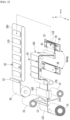
- FIG. 1 is a perspective view showing an electrode assembly manufacturing apparatus according to an embodiment of the present disclosure.
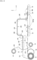
- FIG. 2 is a front view of the electrode assembly manufacturing apparatus of FIG. 1 .
- FIG. 3 is a plan view showing the moving state of the positive electrode piece 110 in the electrode assembly manufacturing apparatus of FIG. 1 .
- an electrode assembly manufacturing apparatus may comprise first and second separator supply units 15 that supplies a first separator sheet and a second separator sheet, respectively, a first electrode supply unit 10 that supplies a first electrode sheet, lamination units 160 and 170 that form an electrode-separator assembly sheet, a second electrode supply unit 20 that supplies a second electrode sheet, a stack unit 30 on which an electrode assembly is seated, and a holding unit 40 (see FIGS. 4 and 5 ) that moves a positive electrode piece 110 to the stack unit 30.
- the first and second separator supply units 15 are disposed at the upper part and the lower part, respectively, and a path along which the plurality of first electrode pieces 120 provided from the first electrode supply unit 10 moves can be formed between them.
- the first electrode supply unit 10 may include an unwinding roll that releases the first electrode sheet, and may further include a first cutting part 12 that cuts the first electrode sheet to form a plurality of first electrode pieces 120.
- the first electrode piece 120 may be a negative electrode.
- the second electrode supply unit 20 may include an unwinding roll that releases the second electrode sheet, and may further include a second cutting part 22 that cuts the second electrode sheet to form a plurality of second electrode pieces 110.
- the second electrode piece 110 may be a positive electrode.
- the electrode assembly manufacturing apparatus according to the present embodiment may further include a transmission unit 300 that transmits the plurality of second electrode pieces 110.
- the electrode assembly manufacturing apparatus according to the present embodiment may further include an alignment unit 62 that aligns the plurality of second electrode pieces 110 moving through the transmission unit 300.
- the lamination unit may comprises a heater 160 and a pressurizing device 170 so that the first and second separator sheets 130 (see FIGS. 4 and 5 ) and the first electrode piece 120 interposed between them are joined to each other.
- the first and second separator sheets and the first electrode piece 120 may be joined to each other by a lamination unit to form the first electrode-separator assembly sheet 150.
- the electrode assembly manufacturing apparatus may further comprise a moving unit 180 that moves the first electrode-separator assembly sheet 150 in order to laminate the plurality of first electrode-separator assemblies 155 (see FIGS. 4 and 5 ) formed in the lamination unit on the stack unit 30.
- the moving unit 180 may be at least one roller.
- the moving unit 180 may change the moving direction of the first electrode-separator assembly sheet 150. For example, as shown in FIGS. 1 and 2 , the first electrode-separator assembly sheet 150 that has passed through the pressurizing device 170 moves in the z-axis direction and then can change its direction in the x-axis direction by the moving unit 180.
- the first electrode-separator assembly sheet 150 which had been moved in the x-axis direction, may change its direction in the -z-axis direction while passing through the moving unit 180 once again. At this time, a gap vision 63 for measuring the width or gap of the first electrode-separator assembly sheet 150 may be added.
- the electrode assembly manufacturing apparatus may further comprise a stage 35 on which the stack unit 30 is seated.
- the stage 35 may be a table using a 3-axis motor, and may be used to adjust the alignment of the stack unit 30, and the like.
- a fixing member 33 is formed on the stage 35 to prevent the stack unit 30 from moving.
- FIGS. 4 and 5 are side views showing the operation of the electrode assembly manufacturing apparatus of FIG. 1 .
- the electrode assembly manufacturing apparatus may comprise, as shown in FIG. 7 , a first electrode supply unit 10 that supplies a first electrode-separator assembly sheet 150 including two sheet-like separators 130, and a plurality of first electrode pieces 120 continuously located between the inner side surfaces of the separators 130 facing each other, a second electrode supply unit 20 that supplies a second electrode piece 110 laminated on the outer side surface of the separator 130 of the first electrode-separator assembly sheet 150 supplied from the first electrode supply unit 10, a stack unit 30 on which an electrode assembly 100 is seated, wherein the electrode assembly 100 is formed by laminating the first electrode-separator assembly 155, which is part of the first electrode-separator assembly sheet 150, and the second electrode piece 110, and a holding unit 40 that holds the second electrode piece 110 from the second electrode supply unit 20 and moves the second electrode piece 110 toward the stack unit 30.
- the first electrode may be a negative electrode
- the second electrode may be
- the plurality of second electrode pieces 110 provided via the second electrode supply unit 20 may move in one direction in the state of being aligned via the transmission unit 300 or while being aligned by the alignment unit 62 or the like. Before moving the second electrode piece 110 located in the transfer unit 300 to the stack unit 30, the second electrode piece 110 may be temporarily seated on the buffer table 32.
- the buffer table 32 includes a first buffer table and a second buffer table, and the stack unit 30 is disposed between the first buffer table and the second buffer table and can reciprocate between the first buffer table and the second buffer table.
- the second electrode piece 110 is supplied from the buffer tables 32 formed in plural numbers, thereby being able to improve the productivity of the electrode assembly 100 of the electrode assembly manufacturing apparatus according to the present embodiment.
- the stack unit 30 may be formed between the buffer tables 32 adjacent to each other in the plurality of buffer tables 32.
- the stack unit 30 is formed between the first and second buffer tables 32, one each on the left and right sides, and may move and/or reciprocate between the first buffer table and the second buffer table.
- the stack unit 30 may move and/or reciprocate on a straight line that forms the shortest distance between the first buffer table 32 and the second buffer table 32 when viewed in a plan view.
- the holding unit 40 can move between the buffer table 32 and the stack unit 30. Specifically, the holding unit 40 may hold the second electrode piece 110 from the buffer table 32 adjacent to the holding unit 40, move the held second electrode piece 110 to the stack unit 30, and laminate it on the stack unit 30. At this time, at the moment when the second electrode piece 110 is laminated on the electrode assembly 100 (see FIG. 8 ) of the stack unit 30 by the holding unit 40, the first electrode-separator assembly 155 may be disposed on the uppermost part of the electrode assembly 100 (see FIG. 8 ) of the stack unit 30. Therefore, the second electrode piece 110 may be laminated so as to be located on the outer side surface of the separator 130 of the first electrode-separator assembly 155.
- the stack unit 30 may laminate the first electrode-separator assembly 155 on the stack unit 30 or on the second electrode piece 110, while moving between the first buffer table 32-1 on the right side and the second buffer table 32-2 on the left side.
- the stack unit 30 can receive transmission of the second electrode piece 110 from the holding unit 40 while moving between the first buffer table 32-1 and the second buffer table 32-2.
- the 1-1 electrode-separator assembly 155-1 Before receiving transmission of the second electrode piece 110, the 1-1 electrode-separator assembly 155-1 may be seated on the stack unit 30.
- the 1-1 electrode-separator assembly 155-1 may be seated on the stack unit 30, and the 2-1 electrode piece 110-1 may be laminated on the 1-1 electrode-separator assembly 155.
- the stack unit 30 which has received transmission of the held 2-1 electrode piece 110-1 can move in order to laminate the 1-2 electrode-separator assembly 155-2 of FIG. 5 on the 2-1 electrode piece 110-1.
- the 1-1 electrode-separator assembly 155-1 and the 1-2 electrode-separator assembly 155-2 are portions of the first electrode-separator assembly sheet 150 that passes through a switching roller 37.
- the 1-1 electrode-separator assembly 155-1 and the 1-2 electrode-separator assembly 155-2 may be portions through which the first electrode-separator assembly sheet 150 sequentially passes through the switching roller 37.
- the stack unit 30 may be moved to be adjacent to the second buffer table 32-2 that is located farther from the stack unit 30 among the plurality of buffer tables 32 in order to laminate the 1-2 electrode-separator assembly 155-2. Further, the stack unit 30 is moved to be adjacent to the second buffer table 32-2, thereby making it possible to located the 1-2 electrode-separator assembly 155-2 on the uppermost 2-1 electrode piece 110-1 of the stack unit 30.
- the stack unit 30 is located closer to the second buffer table 32-2 located on the left side, and can receive supply of the 2-2 electrode piece 110-2 therefrom. Subsequently, the stack unit 30 may be moved so as to be located adjacent to the first buffer table 32-1 that is located farther from the stack unit 30 among the buffer tables 32 in order to laminate a new 1-1 electrode-separator assembly 155-1 again. That is, it can be moved similarly to the position of the stack unit 30 in FIG. 4 . Further, the stack unit 30 is moved to be adjacent to the first buffer table 32-1, thereby making it possible to locate the 1-1 electrode-separator assembly 155-1 on the uppermost 2-2 electrode piece 110-2 of the stack unit 30. By repeating such a process, the first electrode-separator assembly 155 and the second electrode piece 110 can be alternately laminated to form an electrode assembly.
- the electrode assembly manufacturing apparatus continuously supplies a plurality of first electrode-separator assemblies 155 from the first electrode-separator assembly sheet 150, and laminates the second electrode piece 110 on the first electrode-separator assembly 155 in both directions while the stack unit 30 rotationally reciprocates, thereby being able to improve the productivity as compared to a conventional electrode assembly manufacturing apparatus.
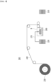
- FIG. 6 is a diagram illustrating a method of manufacturing a negative electrode-separator assembly that is inserted in an electrode assembly manufacturing apparatus according to an embodiment of the present disclosure.
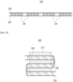
- FIG. 7 is a side view showing a first electrode-separator assembly manufactured through the manufacturing method of FIG. 6 .
- FIG. 8 is a side view showing the electrode assembly of a section A of FIG. 5 , which is an electrode assembly manufactured by an electrode assembly manufacturing apparatus according to an embodiment of the present disclosure.
- the first electrode-separator assembly 155 that is inserted into the electrode assembly manufacturing apparatus may be formed by laminating a long sheet-like separator 130 and a first electrode piece 120.
- the long sheet-like first electrode sheet 121 is inserted into the first electrode-separator assembly manufacturing apparatus, and then the first electrode sheet 121 may be cut to form the first electrode piece 120, but is not limited thereto, and the first electrode piece 120 itself may be inserted.
- the separator 130 may be provided as two long sheet-like separators 130.
- the first electrode-separator assembly sheet 150 may be formed in a state where a plurality of first electrode pieces 120 are interposed between the inner side surfaces of the two separators 130 facing each other. At this time, the plurality of first electrode pieces 120 interposed between the separators 130 may be disposed at intervals from each other in the longitudinal direction (the horizontal direction in FIG. 7 ) of the separator 130.
- first electrode-separator assembly sheet 150 In addition, in order to form the first electrode-separator assembly sheet 150, a heating and laminating process is further performed as shown in FIG. 6 , thereby being able to form a final first electrode-separator assembly sheet 150. Therefore, the separator 130 and the first electrode piece 120 may be joined to each other, and make it possible to form a more robust first electrode-separator assembly sheet 150 and electrode assembly 100.
- the laminating process may be a pressurizing process.
- the electrode assembly 100 of FIG. 8 manufactured by supplying the above-mentioned first electrode-separator assembly 155 to the electrode assembly manufacturing apparatus may be manufactured in such a manner that the first electrode-separator assembly 155 and the second electrode piece 110 are folded and laminated by a zigzag laminating method.
- the electrode assembly 100 can be manufactured by folding the connecting portions formed on the separator 130 in mutually opposite directions.
- the connecting portion may be a portion where the second electrode piece 110 or the first electrode piece 120 is not disposed in the electrode assembly 100, and only the separator 130 is present.
- the stack unit 30 of the electrode assembly manufacturing apparatus laminates the first electrode-separator assembly 155 while moving between the first buffer table 32-1 and the second buffer table 32-2.
- the connecting portions formed on the separator 130 of the electrode assembly 100 may be folded in mutually opposite directions.
- the first electrode piece is a negative electrode piece, and a negative electrode-separator assembly in which such negative electrode piece is laminated to a separator is alternately laminated with the positive electrode piece, but an embodiment in which the positive electrode-separator assembly in which the positive electrode piece is laminated to the separator is alternately laminated with the negative piece can also be available.
- an embodiment in which a negative electrode-separator assembly in which the negative electrode piece is laminated onto the separator is supplied may be more preferable in consideration of the process margin.
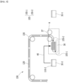
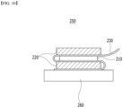
- FIG. 9 is a side view of an electrode assembly manufacturing apparatus according to a comparative example.
- FIG. 10 is a side view showing an electrode assembly manufactured by an electrode assembly manufacturing apparatus according to a comparative example.
- the electrode assembly manufacturing apparatus 200 may include both a positive electrode supply unit and a negative electrode supply unit into which the separator sheet 230 is inserted and the positive electrode piece 210 and the negative electrode piece 220 are supplied.
- the stack unit 260 can move between the positive electrode supply unit and the negative electrode supply unit and receive transmission of the positive electrode piece 210 and the negative electrode piece 220 from the holding unit 270 to form the electrode assembly 250.
- the electrode assembly 250 manufactured by the electrode assembly manufacturing apparatus 200 according to the comparative example includes a single sheet separator 230, it can have a structure of an electrode assembly 250 in which the positive electrode piece 210 or the negative electrode piece 220 is disposed around a single separator sheet 230, rather than a structure in which the negative electrode piece 120 is located between two separators 130.
- the conventional electrode assembly manufacturing apparatus 200 has limits in improving production speed because the positive electrode piece 210 and the negative electrode piece 220 must be laminated on the separator 230, respectively.
- the electrode assembly manufacturing apparatus laminates the second electrode piece 110 after inserting the first electrode-separator assembly 155, which makes it possible to secure productivity that is twice as high as that of the conventional electrode assembly manufacturing apparatus 200.
- the manufacturing method of an electrode assembly comprises a step of forming a first electrode-separator assembly sheet 150 that includes two sheet-like separators 130, and a plurality of first electrode pieces 120 continuously located between inner side surfaces of the separators 130 facing each other; a step of disposing a first electrode-separator assembly 155, which is part of the first electrode-separator assembly sheet 150, in a stack unit 30; a step of laminating a second electrode piece 110 on the outer side surface of the separator 130 of the first electrode-separator assembly 155 disposed in the stack unit 30; and a step of rotationally moving the stack unit 30 to laminate the first electrode-separator assembly 155 on the laminated second electrode piece 110.
- the first electrode-separator assembly 155 may include a 1-1 electrode-separator assembly 155-1 and a 1-2 electrode-separator assembly 155-2
- the second electrode piece 110 may include a 2-1 electrode piece 110-1 and a 2-2 electrode piece 110-2.
- the electrode assembly manufacturing method according to the present embodiment may comprise a step of laminating the 2-2 electrode piece 110-2 on one surface of the 1-2 electrode separator assembly 155-2 that is located on the opposite side to the surface of the 1-2 electrode separator assembly 155-2 facing the 2-1 electrode piece 110-1.
- the step of laminating a second electrode piece 110 on the outer side surface of the separator 130 of the first electrode-separator assembly 155 disposed in the stack unit 30 may be a step in which a holding unit 40 holds a second electrode piece 110 from a buffer table 32, and the held second electrode piece 110 is laminated on the first electrode-separator assembly 155 disposed in the stack unit 30.
- the stack unit 30 is located between the first buffer table 32-1 and the second buffer table 32-2, and can move and reciprocate between them, as mentioned above. Therefore, the step of moving the stack unit 30 to laminate the first electrode-separator assembly 155 on the laminated second electrode piece 110 may be a step in which the stack unit 30 moves between the first buffer table 32-1 and the second buffer table 32-2, and the first electrode-separator assembly 155 may be laminated on the uppermost second electrode piece 110 of the stack unit 30.
- the manufacturing method of an electrode assembly forms the first electrode-separator assembly sheet 150, receives supply of the second electrode pieces 110 from a plurality of buffer tables 32, and laminates them, thereby being able to provide a manufacturing method of an electrode assembly having further improved productivity.
Landscapes
- Chemical & Material Sciences (AREA)
- Chemical Kinetics & Catalysis (AREA)
- Electrochemistry (AREA)
- General Chemical & Material Sciences (AREA)
- Engineering & Computer Science (AREA)
- Manufacturing & Machinery (AREA)
- Secondary Cells (AREA)
Applications Claiming Priority (3)
| Application Number | Priority Date | Filing Date | Title |
|---|---|---|---|
| KR20220112122 | 2022-09-05 | ||
| KR1020230116652A KR20240033671A (ko) | 2022-09-05 | 2023-09-04 | 전극 조립체 제조 장치 및 이를 사용한 제조 방법 |
| PCT/KR2023/013205 WO2024053977A1 (fr) | 2022-09-05 | 2023-09-05 | Dispositif de fabrication d'ensemble électrode et son procédé de fabrication |
Publications (2)
| Publication Number | Publication Date |
|---|---|
| EP4503217A1 true EP4503217A1 (fr) | 2025-02-05 |
| EP4503217A4 EP4503217A4 (fr) | 2025-08-20 |
Family
ID=90191440
Family Applications (1)
| Application Number | Title | Priority Date | Filing Date |
|---|---|---|---|
| EP23863449.7A Pending EP4503217A4 (fr) | 2022-09-05 | 2023-09-05 | Dispositif de fabrication d'ensemble électrode et son procédé de fabrication |
Country Status (5)
| Country | Link |
|---|---|
| US (1) | US20260038862A1 (fr) |
| EP (1) | EP4503217A4 (fr) |
| JP (1) | JP2025513358A (fr) |
| CN (1) | CN119256418A (fr) |
| WO (1) | WO2024053977A1 (fr) |
Family Cites Families (14)
| Publication number | Priority date | Publication date | Assignee | Title |
|---|---|---|---|---|
| JP4351737B2 (ja) * | 2007-05-02 | 2009-10-28 | エナックス株式会社 | 連続セパレータ及びシート状電極の積層装置 |
| KR101255351B1 (ko) * | 2009-04-28 | 2013-04-16 | 에스케이이노베이션 주식회사 | 2차 전지 내부 셀 스택 적층 장치 및 방법 |
| CN103081200B (zh) * | 2010-08-11 | 2015-08-19 | 日本自动精机株式会社 | 正负极板的层积方法及其装置 |
| KR20180001458A (ko) * | 2016-06-27 | 2018-01-04 | 삼성에스디아이 주식회사 | 이차 전지용 스택 장치, 이를 이용한 스택 방법 및 이에 따른 이차 전지 |
| JP6635204B2 (ja) * | 2016-12-21 | 2020-01-22 | 株式会社村田製作所 | 電極積層体の製造装置 |
| HUE062872T2 (hu) * | 2018-04-20 | 2023-12-28 | Bosch Gmbh Robert | Eljárás elektróda elrendezés kialakítására akkumulátor cellához és akkumulátor cella |
| CN115244745A (zh) * | 2020-03-25 | 2022-10-25 | 株式会社Lg新能源 | 制造单元电芯的设备和方法 |
| KR102849368B1 (ko) * | 2020-03-25 | 2025-08-25 | 주식회사 엘지에너지솔루션 | 셀 제조 장치 및 방법 |
| JP7587934B2 (ja) * | 2020-07-14 | 2024-11-21 | 株式会社京都製作所 | 積層セルの製造装置 |
| KR102930038B1 (ko) * | 2020-07-16 | 2026-02-25 | 엘지전자 주식회사 | 이차전지 스텍킹 장비 |
| KR102886043B1 (ko) * | 2021-01-08 | 2025-11-14 | 주식회사 엘지에너지솔루션 | 전극셀 제조장치 및 그 제어 방법 |
| KR102713229B1 (ko) | 2021-02-03 | 2024-10-04 | (주)이녹스첨단소재 | 복합 방열 시트 및 이를 포함하는 디스플레이 부품 |
| KR102370749B1 (ko) * | 2021-09-27 | 2022-03-08 | 주식회사 신룡 | 초기 얼라인수단을 갖는 이차전지용 셀 스택 적층장치 및 초기 얼라인 방법 |
| TWI806396B (zh) | 2022-01-28 | 2023-06-21 | 開曼群島商粉迷科技股份有限公司 | 提供使用者有興趣區域內容的方法與系統 |
-
2023
- 2023-09-05 JP JP2024561844A patent/JP2025513358A/ja active Pending
- 2023-09-05 US US18/996,191 patent/US20260038862A1/en active Pending
- 2023-09-05 CN CN202380040345.7A patent/CN119256418A/zh active Pending
- 2023-09-05 EP EP23863449.7A patent/EP4503217A4/fr active Pending
- 2023-09-05 WO PCT/KR2023/013205 patent/WO2024053977A1/fr not_active Ceased
Also Published As
| Publication number | Publication date |
|---|---|
| EP4503217A4 (fr) | 2025-08-20 |
| US20260038862A1 (en) | 2026-02-05 |
| CN119256418A (zh) | 2025-01-03 |
| WO2024053977A1 (fr) | 2024-03-14 |
| JP2025513358A (ja) | 2025-04-24 |
Similar Documents
| Publication | Publication Date | Title |
|---|---|---|
| JP6093369B2 (ja) | 電極組立体及びこれを含む電気化学素子 | |
| EP3439095B1 (fr) | Appareil et procédé de fabrication d'ensemble électrode et ensemble électrode fabriqué à l'aide de ces derniers | |
| KR101531234B1 (ko) | 이차 전지용 고속 스태킹 장치 및 방법 | |
| KR101837724B1 (ko) | 적층식 이차전지 제조방법 | |
| JP5852256B2 (ja) | 電極組立体、電極組立体の製造工程及び電極組立体を含む電気化学素子 | |
| KR101291063B1 (ko) | 2차 전지 내부 셀 스택 적층 장치 및 방법 | |
| EP2757625B1 (fr) | Procédé de fabrication d'ensemble électrode et dispositif électrochimique | |
| KR20180133235A (ko) | 전극 조립체 제조 시스템 및 방법 | |
| EP2874225A1 (fr) | Procédé pour fixer un ensemble électrode à l'aide d'une bande | |
| KR20140035646A (ko) | 2차 전지 내부 셀 스택 방법 및 이를 이용하여 제조되는 셀 스택 | |
| JP2015072834A (ja) | 切断装置及び切断方法 | |
| KR102820359B1 (ko) | 폴딩형 전극조립체 및 그 제조 방법 | |
| KR102790995B1 (ko) | 전극 조립체 제조 장치 및 이를 사용한 제조 방법 | |
| EP4503217A1 (fr) | Dispositif de fabrication d'ensemble électrode et son procédé de fabrication | |
| EP4513605A1 (fr) | Dispositif de fabrication d'ensemble électrode et procédé de fabrication correspondant | |
| EP4340084B1 (fr) | Dispositif de pliage d'ensemble d'électrodes et procédé de pliage d'ensemble d'électrodes | |
| EP4261968A1 (fr) | Ensemble électrode et élément de batterie le comprenant | |
| EP4235888B1 (fr) | Dispositif de fabrication d'un ensemble d'électrodes et procédé utilisant celui-ci | |
| EP3486989A1 (fr) | Procédé de fabrication de batterie secondaire stratifiée | |
| EP4550512A1 (fr) | Procédé de fabrication d'ensemble électrode à aptitude au traitement améliorée, et ensemble électrode ainsi fabriqué | |
| US20230142281A1 (en) | Method for Manufacturing Secondary Battery and Apparatus for Manufacturing Secondary Battery |
Legal Events
| Date | Code | Title | Description |
|---|---|---|---|
| STAA | Information on the status of an ep patent application or granted ep patent |
Free format text: STATUS: THE INTERNATIONAL PUBLICATION HAS BEEN MADE |
|
| PUAI | Public reference made under article 153(3) epc to a published international application that has entered the european phase |
Free format text: ORIGINAL CODE: 0009012 |
|
| STAA | Information on the status of an ep patent application or granted ep patent |
Free format text: STATUS: REQUEST FOR EXAMINATION WAS MADE |
|
| 17P | Request for examination filed |
Effective date: 20241028 |
|
| AK | Designated contracting states |
Kind code of ref document: A1 Designated state(s): AL AT BE BG CH CY CZ DE DK EE ES FI FR GB GR HR HU IE IS IT LI LT LU LV MC ME MK MT NL NO PL PT RO RS SE SI SK SM TR |
|
| A4 | Supplementary search report drawn up and despatched |
Effective date: 20250723 |
|
| RIC1 | Information provided on ipc code assigned before grant |
Ipc: H01M 10/04 20060101AFI20250717BHEP |
|
| DAV | Request for validation of the european patent (deleted) | ||
| DAX | Request for extension of the european patent (deleted) |