EP4503398A1 - Integrierter motorbremswiderstand - Google Patents
Integrierter motorbremswiderstand Download PDFInfo
- Publication number
- EP4503398A1 EP4503398A1 EP23189130.0A EP23189130A EP4503398A1 EP 4503398 A1 EP4503398 A1 EP 4503398A1 EP 23189130 A EP23189130 A EP 23189130A EP 4503398 A1 EP4503398 A1 EP 4503398A1
- Authority
- EP
- European Patent Office
- Prior art keywords
- stator
- electric motor
- recess
- resistance element
- laminated core
- Prior art date
- Legal status (The legal status is an assumption and is not a legal conclusion. Google has not performed a legal analysis and makes no representation as to the accuracy of the status listed.)
- Withdrawn
Links
Images




Classifications
-
- H—ELECTRICITY
- H02—GENERATION; CONVERSION OR DISTRIBUTION OF ELECTRIC POWER
- H02K—DYNAMO-ELECTRIC MACHINES
- H02K11/00—Structural association of dynamo-electric machines with electric components or with devices for shielding, monitoring or protection
- H02K11/0094—Structural association with other electrical or electronic devices
-
- H—ELECTRICITY
- H02—GENERATION; CONVERSION OR DISTRIBUTION OF ELECTRIC POWER
- H02K—DYNAMO-ELECTRIC MACHINES
- H02K7/00—Arrangements for handling mechanical energy structurally associated with dynamo-electric machines, e.g. structural association with mechanical driving motors or auxiliary dynamo-electric machines
- H02K7/10—Structural association with clutches, brakes, gears, pulleys or mechanical starters
- H02K7/106—Structural association with clutches, brakes, gears, pulleys or mechanical starters with dynamo-electric brakes
-
- H—ELECTRICITY
- H02—GENERATION; CONVERSION OR DISTRIBUTION OF ELECTRIC POWER
- H02K—DYNAMO-ELECTRIC MACHINES
- H02K7/00—Arrangements for handling mechanical energy structurally associated with dynamo-electric machines, e.g. structural association with mechanical driving motors or auxiliary dynamo-electric machines
- H02K7/14—Structural association with mechanical loads, e.g. with hand-held machine tools or fans
- H02K7/145—Hand-held machine tool
-
- H—ELECTRICITY
- H02—GENERATION; CONVERSION OR DISTRIBUTION OF ELECTRIC POWER
- H02K—DYNAMO-ELECTRIC MACHINES
- H02K9/00—Arrangements for cooling or ventilating
- H02K9/02—Arrangements for cooling or ventilating by ambient air flowing through the machine
- H02K9/04—Arrangements for cooling or ventilating by ambient air flowing through the machine having means for generating a flow of cooling medium
- H02K9/06—Arrangements for cooling or ventilating by ambient air flowing through the machine having means for generating a flow of cooling medium with fans or impellers driven by the machine shaft
Definitions
- the present invention relates to an electric motor, in particular as a drive for a machine tool, comprising a power supply, a stator with a stator laminated core and at least two coil windings, a rotor rotatable relative to the stator laminated core, and a control device.
- the present invention relates to a stator for an electric motor.
- the present invention relates to a machine tool with an electric motor.
- Electric motors in particular as drives for machine tools
- a stator essentially contain a stator and a rotor that can rotate relative to the stator to generate a torque.
- the stator For the electric motor to function and in particular for the optional generation of a magnetic field, it is necessary for the stator to have a large number of coil windings around the respective pole teeth or stator teeth.
- a winding wire is wound in several layers around the pole tooth or stator tooth.
- the pole tooth or stator tooth serves as a carrier for the coil winding.
- Motor brakes are often necessary and an integral part of the motor in order to slow down the motor as quickly as possible or to stop the rotation of the rotor relative to the stator.
- an electric motor in particular as a drive for a machine tool, comprising a power supply, a stator with a Stator laminated core and at least two coil windings, a rotor rotatable relative to the stator laminated core and a control device.
- At least one recess for receiving at least one resistance element is contained on an outer surface of the stator laminated core, wherein the at least one resistance element is designed to convert an electrical voltage, which can be generated by the coil windings of the stator during a braking process of the rotor, into heat.
- the at least one recess may extend substantially axially to a stator axis.
- the at least one recess may be positioned in a radial alignment with a pole tooth of the stator.
- a recess may be positioned in radial alignment with each pole tooth.
- the at least one recess may be at least partially filled with a connecting material.
- the connecting material may be at least partially designed as a thermosetting plastic or ceramic mortar.
- At least one ventilation device for generating at least one ventilation flow, wherein the resistance element is at least partially positioned in the ventilation flow for dissipating heat from the resistance element.
- the at least one resistance element may be designed as a high-load resistor.
- Figure 1 shows a machine tool 1 according to an exemplary embodiment.
- the machine tool 1 is designed in the form of a battery-operated drill.
- the machine tool can also be designed in the form of a saw, a grinder, a hammer drill or the like.
- the machine tool 1 designed as a drilling machine essentially contains a housing 2, a handle 3, a tool holder 4 and a power supply 5.
- the housing 2 has a front end 2a, a rear end 2b, an upper end 2c and a lower end 2d.
- the tool holder 4 is positioned at the front end 2a of the housing 2.
- the tool holder 4 serves to pick up and hold a tool.
- the tool is not shown in the figures.
- the tool can be designed in the form of a drill.
- a first end 3a of the handle 3 is positioned at the lower end 2d of the housing 2.
- a battery interface 7 is provided at the second end 3b of the handle 3.
- the handle 3 has an activation switch 8 with which the machine tool 1 can be set to an activation state or a deactivation state.
- the energy supply 5 can be releasably attached to the battery interface 7.
- the energy supply 5 is designed in the form of a battery.
- the energy supply 5 serves to supply the machine tool with electrical energy.
- the energy supply 5 can also be designed as a power cable for connecting the machine tool 1 to a mains power source (socket).
- the energy supply 5 designed as a power cable is not shown in the figures.
- an electric motor 9 as a drive, a transmission device 10, a drive shaft 11, a ventilation device 6 and a control device 12 are positioned inside the housing 2.
- the electric motor 9, the gear device 10, the drive shaft 11 and the tool holder 4 are arranged in relation to one another inside the housing 2 in such a way that the torque generated by the electric motor 9 can be transmitted to the gear device 10, the drive shaft 11 and finally to the tool holder 4 or to the tool.
- the control device 12 is connected to the activation switch 8, the battery interface 7 and the electric motor 9 by means of corresponding lines L.
- the electric motor 9 is designed in the form of a brushless electric motor and essentially contains a stator 16 and a rotor 17, cf. Figure 2 .
- the ventilation device 6 in the form of a fan wheel 6a is positioned so that the fan wheel 6a is driven by the rotor 17.
- ventilation inlets LA1 are provided at the front end 2a of the housing 2 and ventilation outlets LA2 are provided at the rear end 2b of the housing 2.
- a ventilation flow F is generated through the housing 2 to transport waste heat away from the surface of the stator 16.
- the energy supply 5 designed as a rechargeable battery can be releasably connected to the machine tool 1 in order to supply the machine tool 1 with electrical energy.
- the rechargeable battery 5 essentially contains a battery housing 20, a number of energy storage cells 13, a battery interface 14 and a control device 15.
- the energy storage cells 13 can also be referred to as battery cells and are arranged inside the battery housing 20.
- the battery housing 20 essentially contains a cover element 20a, four side walls 20b and a base element 20c.
- the battery interface 14 is arranged on the outside of the cover element 20a and serves for the electrical or electronic as well as mechanical connection of the battery 5 to the machine tool 1 or a charging device.
- the charging device serves to charge the accumulator 5 with electrical energy and is not shown in the figures.
- the battery interface 14 has a positive contact, a negative contact and a communication contact.
- the positive and negative contacts are used to create an electrical circuit when the battery 5 is connected to a machine tool 1 or a charging device.
- the communication contact is used to send and receive data and information in the form of electrical signals.
- the accumulator 5 can also contain a radio communication (e.g. Bluetooth) or wireless communication.
- a radio communication e.g. Bluetooth
- wireless communication e.g.
- the energy storage cells 13 are used to absorb, store and release electrical energy.
- the energy storage cells 13 are cylindrical in shape and are designed based on lithium-ion technology.
- Each energy storage cell 13 contains a contact device at one end which is used to transmit electrical energy.
- the individual contact devices are connected to the control device 15 of the accumulator 5 via corresponding lines.
- the energy storage cells 13 may also be based on another suitable technology.
- the cylindrical shape of the energy storage cells 13 is also optional, so that any other suitable shape or geometry can be selected.
- the energy storage cells 13 it is also possible for the energy storage cells 13 to be designed as pouch cells.
- the accumulator 5 may contain both cylindrical energy storage cells 13 and pouch cells. In particular, it is possible for the accumulator 5 to contain only a single cylindrical energy storage cell 13 and a single pouch cell.
- the control device 15 regulates and controls various functions of the accumulator 5.
- the functions include, among others, the control of the absorption and release of electrical energy into and from the energy storage cells 13.
- the amount of electrical energy that is to be absorbed or released by the energy storage cells 13 is controlled with the help of the control device 15.
- the rotor 17 is positioned inside the stator 16 and is also designed to be rotatable relative to the stator 16.
- the stator 16 contains a stator laminated core 18 with four radially inwardly directed pole teeth 19.
- the stator laminated core 18 essentially consists of a number of profiled sheets stacked on top of one another.
- Two pole teeth 19 are positioned opposite each other. According to an alternative embodiment, more than four pole teeth 19 can also be provided.
- the pole teeth 19 serve to accommodate a coil wire 21 in order to produce a coil 24.
- the coils 24 are connected to the power supply 5 via the control device 12 in order to apply an electrical voltage to the coils 24. In other words: the coils 24 are energized. With the help of the coils 24, an alternating magnetic field is generated, by means of which the rotor 17 is rotated.
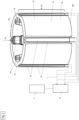
- a number of recesses 22 running axially to a stator axis SA are positioned on an outer surface 23 of the stator laminated core 18.
- Figure 2 is a stator core 18 according to a first embodiment with four recesses 22.
- the recess 22 can also be referred to as a depression, channel, groove or cavity.
- stator laminated core 18 has six recesses 22, cf. Figure 3 .
- the stator laminated core 18 can contain more than six pole teeth 19 and more than six recesses 22.
- the number of pole teeth 19 and recesses 22 do not have to be the same.
- the recesses 22 according to the first and second embodiments on the outer surface 23 are aligned with the pole teeth 19.
- a recess 22 is in radial alignment with a pole tooth 19.
- a recess 22 can also be positioned in a radial alignment between two adjacent pole teeth 19. According to the embodiments shown, the recesses 22 extend over the entire length L of the stator laminated core 18. The length of a recess 22 therefore corresponds to the length of the stator laminated core 18.
- one or more recesses 22 may be shorter than the stator laminated core 18, whereby one or more recesses 22 do not extend over the entire length of the stator laminated core 18.
- a recess 22 serves to accommodate a resistance element 25, which is connected via corresponding lines to the control device 12 and to the coils 24 of the stator 16.
- a resistance element 25 which is connected via corresponding lines to the control device 12 and to the coils 24 of the stator 16.
- FIG 3 The connections between the coils 24 and the respective resistance elements 25 are shown in outline.
- the resistance element 25 is designed as a current-conducting wire in the form of a curve or an arc.
- the rotor 17 must be braked using a braking process.
- an electrical voltage is induced at the coils 24 of the stator 16.
- the induced electrical voltage in the resistance elements 25 can be converted into heat.
- a recess 22 also serves as a flow channel through which a ventilation flow F generated by the ventilation device 6 can flow.
- the fan wheel 6a driven by the rotor 17 generates a ventilation flow F, which flows over the surface of the stator 16 or stator laminated core for cooling.
- the recesses 22 increase the outer surface area 23 of the stator laminated core, which enables better heat dissipation. Furthermore, the recesses 22 guide the ventilation flow F like channels along the resistance elements 25 in a targeted manner and cool them effectively.
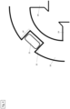
- FIG. 4 a detailed view of the stator laminated core with a recess 22 and resistance element 25 according to a first embodiment is shown. As can be seen, the recess 22 with a resistance element 25 is located between two adjacent pole teeth 19.
- FIG. 5 a detailed view of the stator laminated core with a recess 22 and resistance element 25 according to a second embodiment is shown. As can be seen, the recess 22 with a resistance element 25 is in radial alignment with a pole tooth 19.
- FIG 6 is a detailed view of the stator core with a recess 22 and resistance element 25 according to a third embodiment.
- the recess 22 with a resistance element 25 is located between two adjacent pole teeth 19.
- the recess 22 is almost completely filled with a thermosetting plastic as a connecting material 26.
- the filling height FH of the connecting material 26 is less than the depth of the recess 22.
- the filling height FH of the connecting material 26 can correspond to the depth AT of the recess 22.
- FIG 7 is a detailed view of the stator laminated core with a recess 22 and resistance element 25 according to a fourth embodiment.
- the recess 22 with a resistance element 25 is in radial alignment with a pole tooth 19.
- the recess 22 is almost completely filled with a thermosetting plastic as a connecting material 26.
- the filling height FH of the connecting material is less than the depth of the recess 22.
- the filling height FH of the connecting material 26 can correspond to the depth AT of the recess 22.
Landscapes
- Engineering & Computer Science (AREA)
- Power Engineering (AREA)
- Iron Core Of Rotating Electric Machines (AREA)
Abstract
Elektromotor, insbesondere als Antrieb für eine Werkzeugmaschine, enthaltend eine Energieversorgung, einen Stator mit einem Statorblechpaket und wenigstens zwei Spulenwicklungen, einen relativ zu dem Statorblechpaket rotierbaren Rotor sowie eine Steuereinrichtung.An einer Außenmantelfläche des Statorblechpakets ist wenigstens eine Aussparung zur Aufnahme wenigstens eines Widerstandselements enthalten, wobei das wenigstens eine Widerstandselement zur Umwandlung einer elektrischen Spannung, welche während eines Bremsvorgangs des Rotors durch die Spulenwicklungen des Stators erzeugbar ist, in Wärme ausgestaltet ist.
Description
- Die vorliegende Erfindung betrifft einen Elektromotor, insbesondere als Antrieb für eine Werkzeugmaschine, enthaltend eine Energieversorgung, einen Stator mit einem Statorblechpaket und wenigstens zwei Spulenwicklungen, einen relativ zu dem Statorblechpaket rotierbaren Rotor sowie eine Steuereinrichtung.
- Des Weiteren betrifft die vorliegende Erfindung einen Stator für einen Elektromotor.
- Darüber hinaus betrifft die vorliegende Erfindung eine Werkzeugmaschine mit Elektromotor.
- Aus dem Stand der Technik sind Elektromotoren (insbesondere als Antrieb für Werkzeugmaschinen) bekannt, die zum Erzeugen eines Drehmoments im Wesentlichen einen Stator und einen relativ zu dem Stator drehbaren Rotor enthalten. Für die Funktionsweise des Elektromotors und insbesondere zum wahlweisen Erzeugen eines Magnetfeldes ist es notwendig, dass der Stator eine Vielzahl von Spulenwicklungen um die jeweiligen Polzähne bzw. Statorzähne aufweist. Zum Herstellen einer Spule bzw. Spulenwicklung wird ein Wickeldraht in mehreren Lagen um den Polzahn bzw. Statorzahn gewickelt. Der Polzahn bzw. Statorzahn dient dabei als Träger für die Spulenwicklung.
- Motorbremsen sind häufig notwendig und ein integraler Bestandteil des Motors, um den Motor schnellstmöglich abzubremsen bzw. die Rotation des Rotors relativ zum Stator zu stoppen.
- Bisher am Markt erhältliche und insbesondere aus dem Stand der Technik bekannte Motorbremsen weisen oftmals das Problem auf, das diese relativ groß sind und zudem auch eine gewisse Komplexität aufweisen.
- Es ist damit Aufgabe der vorliegenden Erfindung das vorstehend beschriebene Problem zu lösen.
- Die Aufgabe wird gelöst durch den Gegenstand des unabhängigen Patentanspruchs 1, 9 und 10.
- Weitere vorteilhafte Ausführungsformen des erfindungsgemäßen Gegenstands sind in den entsprechenden abhängigen Patentansprüchen enthalten.
- Die Aufgabe wird dabei insbesondere gelöst durch einen Elektromotor, insbesondere als Antrieb für eine Werkzeugmaschine, enthaltend eine Energieversorgung, einen Stator mit einem Statorblechpaket und wenigstens zwei Spulenwicklungen, einen relativ zu dem Statorblechpaket rotierbaren Rotor sowie eine Steuereinrichtung.
- Erfindungsgemäß ist vorgesehen, dass an einer Außenmantelfläche des Statorblechpakets wenigstens eine Aussparung zur Aufnahme wenigstens eines Widerstandselements enthalten ist, wobei das wenigstens eine Widerstandselement zur Umwandlung einer elektrischen Spannung, welche während eines Bremsvorgangs des Rotors durch die Spulenwicklungen des Stators erzeugbar ist, in Wärme ausgestaltet ist.
- Entsprechend einer vorteilhaften Ausführungsform kann es möglich sein, dass die wenigstens eine Aussparung im Wesentlichen axial zu einer Statorachse verläuft.
- Gemäß einer weiteren vorteilhaften Ausführungsform kann es möglich sein, dass die wenigstens eine Aussparung in einer radialen Ausrichtung zu einem Polzahn des Stators positioniert ist.
- Entsprechend einer weiteren vorteilhaften Ausführungsform kann es möglich sein, dass in radialer Ausrichtung zu jedem Polzahn eine Aussparung positioniert ist.
- Gemäß einer weiteren vorteilhaften Ausführungsform kann es möglich sein, dass die wenigstens eine Aussparung wenigstens teilweise mit einem Verbindungsmaterial befüllt ist.
- Entsprechend einer weiteren vorteilhaften Ausführungsform kann es möglich sein, dass das Verbindungsmaterial wenigstens teilweise als Duroplast oder keramischer Mörtel ausgestaltet ist.
- Gemäß einer alternativen Ausführungsform kann es möglich sein, dass wenigstens eine Lüftungseinrichtung zum Erzeugen wenigstens eines Lüftungsstroms enthalten ist, wobei das Widerstandselement wenigstens teilweise im Lüftungsstrom zum Abtransport einer Wärme des Widerstandselements positioniert ist.
- Entsprechend einer alternativen Ausführungsform kann es möglich sein, dass das wenigstens eine Widerstandselement als Hochlastwiderstand ausgestaltet ist.
- Des Weiteren wird die Aufgabe gelöst durch einen Stator für einen Elektromotor.
- Darüber hinaus wird die Aufgabe gelöst durch Werkzeugmaschine mit Elektromotor.
- Weitere Vorteile ergeben sich aus der folgenden Figurenbeschreibung. In den Figuren sind verschiedene Ausführungsbeispiele der vorliegenden Erfindung dargestellt.
- Die Figuren, die Beschreibung und die Ansprüche enthalten zahlreiche Merkmale in Kombination. Der Fachmann wird die Merkmale zweckmässigerweise auch einzeln betrachten und zu sinnvollen weiteren Kombinationen zusammenfassen.
-
- Figur 1
- eine schematische Seitenansicht auf eine erfindungsgemäße Werkzeugmaschine gemäß einer beispielhaften Ausführungsform mit einem Elektromotor;
- Figur 2
- eine perspektivische Ansicht auf ein Statorblechpaket mit Aussparungen und Widerstandselementen;
- Figur 3
- eine Draufsicht auf einen Stator und Rotor;
- Figur 4
- eine Detailansicht auf das Statorblechpaket mit einer Aussparung und einem Widerstandselement gemäß einem ersten Ausführungsbeispiel;
- Figur 5
- eine Detailansicht auf das Statorblechpaket mit einer Aussparung und einem Widerstandselement gemäß einem zweiten Ausführungsbeispiel;
- Figur 6
- eine Detailansicht auf das Statorblechpaket mit einer Aussparung und einem Widerstandselement gemäß einem dritten Ausführungsbeispiel; und
- Figur 7
- eine Detailansicht auf das Statorblechpaket mit einer Aussparung und einem Widerstandselement gemäß einem vierten Ausführungsbeispiel.
-
Figur 1 zeigt eine Werkzeugmaschine 1 gemäß einer beispielhaften Ausführungsform. Die Werkzeugmaschine 1 ist in Form einer akkubetriebenen Bohrmaschine ausgestaltet. - Gemäß einem alternativen Ausführungsbeispiel kann die Werkzeugmaschine auch in Form einer Säge, eines Schleifgeräts, eines Bohrhammers oder dergleichen ausgestaltet sein.
- Die als Bohrmaschine ausgestaltete Werkzeugmaschine 1 enthält dabei im Wesentlichen ein Gehäuse 2, einen Handgriff 3, eine Werkzeugaufnahme 4 und eine Energieversorgung 5.
- Das Gehäuse 2 weist ein vorderes Ende 2a, ein hinteres Ende 2b, ein oberes Ende 2c und ein unteres Ende 2d auf.
- An dem vorderen Ende 2a des Gehäuses 2 ist die Werkzeugaufnahme 4 positioniert. Die Werkzeugaufnahme 4 dient zum Aufnehmen und Halten eines Werkzeugs. In den Figuren ist das Werkzeug nicht dargestellt.
- In dem vorliegenden Ausführungsbeispiel kann das Werkzeug in Form eines Bohrers ausgestaltet. An dem unteren Ende 2d des Gehäuses 2 ist ein erstes Ende 3a des Handgriffs 3 positioniert. An dem zweiten Ende 3b des Handgriffs 3 ist eine Akku-Schnittstelle 7 vorgesehen.
- Wie in
Figur 1 gezeigt weist der Handgriff 3 einen Aktivierungsschalter 8 auf, mit dem die Werkzeugmaschine 1 in einen Aktivierungszustand oder Deaktivierungszustand eingestellt werden kann. - An die Akku-Schnittstelle 7 kann die Energieversorgung 5 wiederlösbar befestigt werden. In dem vorliegenden Ausführungsbeispiel ist die Energieversorgung 5 in Form eines Akkumulators ausgestaltete. Die Energieversorgung 5 dient zum Versorgen der Werkzeugmaschine mit elektrischer Energie.
- Entsprechend einem alternativen Ausführungsbeispiel kann die Energieversorgung 5 auch als Stromkabel zum Verbinden der Werkzeugmaschine 1 mit einer Netzstromquelle (Steckdose) ausgestaltet sein. Die als Stromkabel ausgestaltete Energieversorgung 5 ist in den Figuren nicht dargestellt.
- Im Inneren des Gehäuses 2 ist im Wesentlichen ein Elektromotor 9 als Antrieb, eine Getriebevorrichtung 10, eine Antriebswelle 11, eine Lüftungseinrichtung 6 und eine Steuereinrichtung 12 positioniert.
- Der Elektromotor 9, die Getriebevorrichtung 10, die Antriebswelle 11 und die Werkzeugaufnahme 4 sind so im Inneren des Gehäuses 2 zueinander angeordnet, dass ein in dem Elektromotor 9 erzeugtes Drehmoment auf die Getriebevorrichtung 10, die Antriebswelle 11 und schließlich auf die Werkzeugaufnahme 4 bzw. auf das Werkzeug übertragen werden kann.
- Die Steuereinrichtung 12 ist mittels entsprechenden Leitungen L mit dem Aktivierungsschalter 8, der Akku-Schnittstelle 7 und dem Elektromotor 9 verbunden.
- Der Elektromotor 9 ist in Form eines bürstenlosen Elektromotors ausgestaltet und enthält im Wesentlichen einen Stator 16 und einen Rotor 17, vgl.
Figur 2 . - An einem hinteren Ende des Stators 16 ist die Lüftungseinrichtung 6 in Form eines Lüfterrads 6a so positioniert, dass das Lüftungsrad 6a durch den Rotor 17 angetrieben wird. Wie in
Figur 1 angedeutet, sind an dem vorderen Ende 2a des Gehäuses 2 Lüftungseinlässe LA1 und an dem hinteren Ende 2b des Gehäuses 2 Lüftungsauslässe LA2 vorgesehen. Wenn das Lüfterrad 6a durch den Rotor 17 angetrieben ist, wird ein Lüftungsstrom F durch das Gehäuse 2 erzeugt zum Abtransport einer Abwärme an der Oberfläche des Stators 16. - Die als Akkumulator ausgestaltete Energieversorgung 5 kann mit der Werkzeugmaschine 1 wiederlösbar verbunden werden, um die Werkzeugmaschine 1 mit elektrischer Energie zu versorgen. Der Akkumulator 5 enthält im Wesentlichen ein Akku-Gehäuse 20, eine Anzahl an Energiespeicherzellen 13, eine Akku-Schnittstelle 14 sowie eine Steuerungseinrichtung 15.
- Die Energiespeicherzellen 13 können auch als Akku-Zellen bezeichnet werden und sind im Inneren des Akku-Gehäuses 20 angeordnet.
- Das Akku-Gehäuse 20 enthält dabei im Wesentlichen ein Deckelelement 20a, vier Seitenwände 20b und ein Bodenelement 20c.
- Die Akku-Schnittstelle 14 ist an der Außenseite des Deckelelements 20a angeordnet und dient zum elektrischen bzw. elektronischen sowie mechanischen Verbinden des Akkumulators 5 mit der Werkzeugmaschine 1 oder einer Ladevorrichtung.
- Die Ladevorrichtung dient zum Laden des Akkumulators 5 mit elektrischer Energie und ist in den Figuren nicht dargestellt.
- Zum elektrischen bzw. elektronischen Verbinden weist die Akku-Schnittstelle 14 einen Pluskontakt, einen Minuskontakt und einen Kommunikationskontakt auf. Der Plus- und Minuskontakt dient zur Erzeugen eines Stromkreises, wenn der Akkumulator 5 mit einer Werkzeugmaschine 1 oder einer Ladevorrichtung verbunden ist. Der Kommunikationskontakt dient zum Senden und Empfangen von Daten sowie Informationen in Form von elektrischen Signalen.
- Alternativ oder zusätzlich kann der Akkumulator 5 auch eine Funkkommunikation (z.B. Bluetooth) bzw. drahtlose Kommunikation enthalten.
- Die Energiespeicherzellen 13 dienen zum Aufnehmen, Speichern und erneuten Abgeben elektrischer Energie. Die Energiespeicherzellen 13 sind in zylindrischer Form sowie auf Basis einer Lithium-lonen-Technologie ausgestaltet. Jede Energiespeicherzelle 13 enthält an einem Ende eine Kontakteinrichtung, die zur Übertragung elektrischer Energie dient. Die einzelnen Kontakteinrichtung sind über entsprechende Leitungen mit der Steuerungseinrichtung 15 des Akkumulators 5 verbunden.
- Alternativ können die Energiespeicherzellen 13 auch auf einer anderen geeigneten Technologie basieren.
- Die zylindrische Form der Energiespeicherzellen 13 ist ebenfalls optional, sodass auch jede andere geeignete Form bzw. Geometrie gewählt werden kann. So ist es insbesondere auch möglich, dass die Energiespeicherzellen 13 als Pouchzellen ausgestaltet sind.
- Es ist zudem auch möglich, dass der Akkumulator 5 sowohl zylindrische Energiespeicherzellen 13 als auch Pouch-Zellen enthält. Es ist insbesondere möglich, dass der Akkumulator 5 lediglich eine einzige zylindrische Energiespeicherzelle 13 und eine einzige Pouchzelle enthält.
- Die Steuerungseinrichtung 15 regelt und steuert verschiedene Funktionen des Akkumulators 5. Zu den Funktion gehört unter anderen die Steuerung der Aufnahme und Abgabe von elektrischer Energie in bzw. aus den Energiespeicherzellen 13. Darüber hinaus wird mit Hilfe der Steuerungseinrichtung 15 die Menge an elektrischer Energie gesteuert, die von den Energiespeicherzellen 13 aufgenommen oder abgegeben werden sollen.
- Wie in
Figur 3 angedeutet ist der Rotor 17 im Inneren des Stators 16 positioniert und zudem drehbar zu dem Stator 16 ausgestaltet. - Wie in
Figur 2 gezeigt enthält der Stator 16 ein Statorblechpaket 18 mit vier radial nach innen gerichtete Polzähne 19. Das Statorblechpaket 18 besteht im Wesentlichen aus einer Anzahl an übereinander gestapelten Profilblechen. - Es sind jeweils zwei Polzähne 19 einander gegenüber positioniert. Gemäß einer alternativen Ausführungsform können auch mehr als vier Polzähne 19 vorgesehen sein. Die Polzähne 19 dienen zum jeweiligen Aufnehmen einer Spulendrahts 21 zum Erzeugen einer Spule 24. Die Spulen 24 sind entsprechend über die Steuereinrichtung 12 mit der Energieversorgung 5 verbunden, um eine elektrische Spannung an die Spulen 24 anzulegen. Mit anderen Worten: die Spulen 24 werden bestromt. Mit Hilfe der Spulen 24 wird ein abwechselndes Magnetfeld erzeugt, durch welches der Rotor 17 gedreht wird.
- An einer Außenmantelfläche 23 des Statorblechpakets 18 sind eine Anzahl an axial zu einer Statorachse SA verlaufende Aussparung 22 positioniert. In
Figur 2 ist ein Statorblechpaket 18 gemäß einem ersten Ausführungsbeispiel mit vier Aussparungen 22 gezeigt. Die Aussparung 22 kann auch als Vertiefung, Rinne, Nut oder Kavität bezeichnet werden. - Gemäß einem zweiten Ausführungsbeispiel hat das Statorblechpaket 18 sechs Aussparungen 22, vgl.
Figur 3 . - Entsprechend einem alternativen Ausführungsbeispiel kann das Statorblechpaket 18 mehr als sechs Polzähne 19 sowie mehr als sechs Aussparungen 22 enthalten. Die Anzahl an Polzähnen 19 und Aussparungen 22 müssen dabei nicht gleich sein.
- Wie in den
Figuren 2 und3 zu erkennen ist, sind die Aussparungen 22 gemäß dem ersten und zweiten Ausführungsbeispiel an der Außenmantelfläche 23 mit den Polzähnen 19 entsprechend ausgerichtet. Mit anderen Worten: eine Aussparung 22 befindet sich in radialer Ausrichtung zu einem Polzahn 19. - Wie nachfolgend noch beschrieben, kann eine Aussparung 22 in radialer Ausrichtung auch zwischen zwei benachbarten Polzähnen 19 positioniert sein. Gemäß den gezeigten Ausführungsbeispielen erstrecken sich die Aussparungen 22 über die gesamte Länge L des Statorblechpakets 18. Die Länge einer Aussparung 22 entspricht damit der Länge des Statorblechpakets 18.
- Es ist entsprechend einem alternativen, in den Figuren nicht dargestellten Ausführungsbeispiel auch möglich, dass ein oder mehrere Aussparungen 22 kürzer sind als das Statorblechpaket 18, wodurch sich ein oder mehrere Aussparungen 22 nicht über die gesamte Länge des Statorblechpakets 18 erstrecken.
- Wie in den Figuren angedeutet, dient eine Aussparung 22 zur Aufnahme eines Widerstandselements 25, welche jeweils über entsprechenden Leitungen mit der Steuereinrichtung 12 sowie mit den Spulen 24 des Stators 16 verbunden ist. In
Figur 3 sind die Verbindungen zwischen den Spulen 24 mit den jeweiligen Widerstandselementen 25 andeutungsweise dargestellt. In den Ausführungsbeispiel inFigur 2 ist das Widerstandselement 25 als stromleitenden Draht in Form einer Kurve oder eines Bogens ausgestaltet. - Wenn die Drehgeschwindigkeit des Rotors 17 relativ zu dem Stator 16 reduziert oder der Rotor 17 sogar komplett gestoppt werden soll, muss mit Hilfe eines Bremsvorgang der Rotor 17 gebremst werden. Beim Bremsen des Rotors 17 wird an den Spulen 24 des Stators 16 eine elektrische Spannung induziert. Durch die Verbindung der Spulen 24 über Leitungen L mit den jeweiligen Widerstandselementen 25, kann die induzierte elektrische Spannung in den Widerstandselementen 25 in Wärme umgewandelt werden.
- Des Weiteren dient eine Aussparung 22 auch als Strömungskanal, durch den ein Lüftungsstrom F erzeugt von der Lüftungseinrichtung 6 strömen kann.
- Wie vorstehend bereits beschrieben, erzeugt das von dem Rotor 17 angetriebene Lüfterrad 6a einen Lüftungsstrom F, welcher zum Kühlen über die Manteloberfläche des Stators 16 bzw. Statorblechpakets strömt. Die Aussparungen 22 erhöhen die Außenmantelfläche 23 des Statorblechpakets, wodurch ein besserer Wärmeabtransport möglich ist. Des Weiteren leiten die Aussparungen 22 den Lüftungsstrom F wie Kanäle gezielt an den Widerstandselementen 25 entlang und kühlen diese effektiv.
- Entsprechend einem weiteren alternativen Ausführungsbeispiel ist es auch möglich, dass sich nicht in jeder Aussparung 22 ein Widerstandselement 25 befindet. Vorzugsweise befinden sich in zwei gegenüberliegenden Aussparungen 22 jeweils ein Widerstandselement 25.
- In
Figur 4 ist eine Detailansicht auf das Statorblechpaket mit einer Aussparung 22 und Widerstandselement 25 gemäß einem ersten Ausführungsbeispiel gezeigt. Wie zu erkennen ist, befindet sich die Aussparung 22 mit einem Widerstandselement 25 zwischen zwei benachbarten Polzähnen 19. - In
Figur 5 ist eine Detailansicht auf das Statorblechpaket mit einer Aussparung 22 und Widerstandselement 25 gemäß einem zweiten Ausführungsbeispiel gezeigt. Wie zu erkennen ist, befindet sich die Aussparung 22 mit einem Widerstandselement 25 in radialer Ausrichtung zu einem Polzahn 19. - In
Figur 6 ist eine Detailansicht auf das Statorblechpaket mit einer Aussparung 22 und Widerstandselement 25 gemäß einem dritten Ausführungsbeispiel gezeigt. Wie zu erkennen ist, befindet sich die Aussparung 22 mit einem Widerstandselement 25 zwischen zwei benachbarten Polzähnen 19. Die Aussparung 22 ist mit einem Duroplast als Verbindungsmaterial 26 nahezu vollständig gefüllt. Wie inFigur 6 angedeutet ist die Füllhöhe FH des Verbindungsmaterials 26 geringer als die Tiefe der Aussparung 22. - Gemäß einer alternativen Ausführungsform kann die Füllhöhe FH des Verbindungsmaterials 26 der Tiefe AT der Aussparung 22 entsprechen.
- In
Figur 7 ist eine Detailansicht auf das Statorblechpaket mit einer Aussparung 22 und Widerstandselement 25 gemäß einem vierten Ausführungsbeispiel gezeigt. Wie zu erkennen ist, befindet sich die Aussparung 22 mit einem Widerstandselement 25 in radialer Ausrichtung zu einem Polzahn 19. Die Aussparung 22 ist mit einem Duroplast als Verbindungsmaterial 26 nahezu vollständig gefüllt. Wie inFigur 7 angedeutet ist die Füllhöhe FH des Verbindungsmaterials geringer als die Tiefe der Aussparung 22. - Gemäß einer alternativen Ausführungsform kann die Füllhöhe FH des Verbindungsmaterials 26 der Tiefe AT der Aussparung 22 entsprechen.
-
- 1
- Werkzeugmaschine
- 2
- Gehäuse
- 2a
- vorderes Ende des Gehäuses
- 2b
- hinteres Ende des Gehäuses
- 2c
- oberes Ende des Gehäuses
- 2d
- unteres Ende des Gehäuses
- 3
- Handgriff
- 3a
- erstes Ende des Handgriffs
- 3b
- zweites Ende des Handgriffs
- 4
- Werkzeugaufnahme
- 5
- Energieversorgung
- 6
- Lüftungseinrichtung
- 6a
- Lüfterrad
- 7
- Akku-Schnittstelle
- 8
- Aktivierungsschalter
- 9
- Elektromotor
- 10
- Getriebevorrichtung
- 11
- Antriebswelle
- 12
- Steuereinrichtung
- 13
- Energiespeicherzelle
- 14
- Akku-Schnittstelle
- 15
- Steuerungseinrichtung
- 16
- Stator
- 16a
- oberes Ende des Stators
- 16b
- unteres Ende des Stators
- 17
- Rotor
- 18
- Statorblechpaket
- 19
- Polzahn
- 20
- Akku-Gehäuse
- 20a
- Deckelelement
- 20b
- Seitenwand
- 20c
- Bodenelement
- 21
- Spulendraht
- 22
- Aussparung
- 23
- Außenmantelfläche des Statorblechpakets
- 24
- Spule
- 25
- Widerstandselement
- 26
- Verbindungsmaterial
- LA1
- Lüftungseinlass
- LA2
- Lüftungsauslass
- F
- Lüftungsstrom
- Lsb
- Länge des Statorblechpakets
- L
- Leitung
- SA
- Statorachse
- FH
- Füllhöhe des Verbindungsmaterials
- AT
- Tiefe der Aussparung
Claims (10)
- Elektromotor (9), insbesondere als Antrieb für eine Werkzeugmaschine (1), enthaltend eine Energieversorgung (5), einen Stator (16) mit einem Statorblechpaket (18) und wenigstens zwei Spulen (24), einen relativ zu dem Statorblechpaket (18) rotierbaren Rotor (17) sowie eine Steuereinrichtung (12),
dadurch gekennzeichnet, dass an einer Außenmantelfläche (23) des Statorblechpakets (18) wenigstens eine Aussparung (22) zur Aufnahme wenigstens eines Widerstandselements (25) enthalten ist, wobei das wenigstens eine Widerstandselement (25) zur Umwandlung einer elektrischen Spannung, welche während eines Bremsvorgangs des Rotors (17) durch die Spulen (24) des Stators (16) erzeugbar ist, in Wärme ausgestaltet ist. - Elektromotor (9) nach Anspruch 1,
dadurch gekennzeichnet, dass die wenigstens eine Aussparung (22) im Wesentlichen axial zu einer Statorachse (SA) verläuft. - Elektromotor (9) nach Anspruch 1 oder 2,
dadurch gekennzeichnet, dass die wenigstens eine Aussparung (22) in einer radialen Ausrichtung zu einem Polzahn (19) des Stators (16) positioniert ist. - Elektromotor (9) nach Anspruch 1 oder 2,
dadurch gekennzeichnet, dass in radialer Ausrichtung zu jedem Polzahn (19) eine Aussparung (22) positioniert ist. - Elektromotor (9) nach wenigstens einem der Ansprüche 1 bis 4,
dadurch gekennzeichnet, dass die wenigstens eine Aussparung (22) wenigstens teilweise mit einem Verbindungsmaterial befüllt ist. - Elektromotor (9) nach Anspruch 5,
dadurch gekennzeichnet, dass das Verbindungsmaterial (26) wenigstens teilweise als Duroplast oder keramischer Mörtel ausgestaltet ist. - Elektromotor (9) nach wenigstens einem der Ansprüche 1 bis 6,
dadurch gekennzeichnet, dass wenigstens eine Lüftungseinrichtung (6) zum Erzeugen wenigstens eines Lüftungsstroms (F) enthalten ist, wobei das Widerstandselement (25) wenigstens teilweise im Lüftungsstrom (F) zum Abtransport einer Wärme des Widerstandselements (25) positioniert ist. - Elektromotor (9) nach wenigstens einem der Ansprüche 1 bis 7,
dadurch gekennzeichnet, dass das wenigstens eine Widerstandselement (25) als Hochlastwiderstand ausgestaltet ist. - Stator (16) für einen Elektromotor (9) nach wenigstens einem der Ansprüche 1 bis 8.
- Werkzeugmaschine (1) mit Elektromotor (9) nach wenigstens einem der Ansprüche 1 bis 8.
Priority Applications (3)
| Application Number | Priority Date | Filing Date | Title |
|---|---|---|---|
| EP23189130.0A EP4503398A1 (de) | 2023-08-02 | 2023-08-02 | Integrierter motorbremswiderstand |
| CN202480038816.5A CN121312044A (zh) | 2023-08-02 | 2024-07-18 | 集成式马达制动电阻 |
| PCT/EP2024/070410 WO2025026757A1 (de) | 2023-08-02 | 2024-07-18 | Integrierter motorbremswiderstand |
Applications Claiming Priority (1)
| Application Number | Priority Date | Filing Date | Title |
|---|---|---|---|
| EP23189130.0A EP4503398A1 (de) | 2023-08-02 | 2023-08-02 | Integrierter motorbremswiderstand |
Publications (1)
| Publication Number | Publication Date |
|---|---|
| EP4503398A1 true EP4503398A1 (de) | 2025-02-05 |
Family
ID=87556156
Family Applications (1)
| Application Number | Title | Priority Date | Filing Date |
|---|---|---|---|
| EP23189130.0A Withdrawn EP4503398A1 (de) | 2023-08-02 | 2023-08-02 | Integrierter motorbremswiderstand |
Country Status (3)
| Country | Link |
|---|---|
| EP (1) | EP4503398A1 (de) |
| CN (1) | CN121312044A (de) |
| WO (1) | WO2025026757A1 (de) |
Citations (5)
| Publication number | Priority date | Publication date | Assignee | Title |
|---|---|---|---|---|
| US3260873A (en) * | 1963-08-16 | 1966-07-12 | Black & Decker Mfg Co | Mounting and cooling means for an energy-dissipating resistor in an electrically-operated device |
| DE29909530U1 (de) * | 1999-06-01 | 1999-08-12 | MAN Roland Druckmaschinen AG, 63075 Offenbach | Antrieb für eine Druckmaschine |
| DE10052910A1 (de) * | 2000-09-28 | 2002-07-25 | Loher Ag | Elektrische Maschine |
| US20200259428A1 (en) * | 2019-02-12 | 2020-08-13 | Goodrich Actuation Systems Limited | Motor with regenerative braking resistor |
| US20230155430A1 (en) * | 2019-06-05 | 2023-05-18 | Milwaukee Electric Tool Corporation | Electric motor |
-
2023
- 2023-08-02 EP EP23189130.0A patent/EP4503398A1/de not_active Withdrawn
-
2024
- 2024-07-18 CN CN202480038816.5A patent/CN121312044A/zh active Pending
- 2024-07-18 WO PCT/EP2024/070410 patent/WO2025026757A1/de active Pending
Patent Citations (5)
| Publication number | Priority date | Publication date | Assignee | Title |
|---|---|---|---|---|
| US3260873A (en) * | 1963-08-16 | 1966-07-12 | Black & Decker Mfg Co | Mounting and cooling means for an energy-dissipating resistor in an electrically-operated device |
| DE29909530U1 (de) * | 1999-06-01 | 1999-08-12 | MAN Roland Druckmaschinen AG, 63075 Offenbach | Antrieb für eine Druckmaschine |
| DE10052910A1 (de) * | 2000-09-28 | 2002-07-25 | Loher Ag | Elektrische Maschine |
| US20200259428A1 (en) * | 2019-02-12 | 2020-08-13 | Goodrich Actuation Systems Limited | Motor with regenerative braking resistor |
| US20230155430A1 (en) * | 2019-06-05 | 2023-05-18 | Milwaukee Electric Tool Corporation | Electric motor |
Also Published As
| Publication number | Publication date |
|---|---|
| WO2025026757A1 (de) | 2025-02-06 |
| CN121312044A (zh) | 2026-01-09 |
Similar Documents
| Publication | Publication Date | Title |
|---|---|---|
| DE102017105357A1 (de) | Elektrische maschine für ein fahrzeug | |
| DE102017107165A1 (de) | Statorkühlung für elektrische maschinen | |
| DE10336402A1 (de) | Regeneratives Energie-Management-System auf der Basis eines Schwungrads | |
| DE102016109584A1 (de) | Oberflächennutenmuster für Permanentmagnetmaschinenrotoren | |
| DE102012100668A1 (de) | Elektromotor | |
| DE102014211615A1 (de) | Handwerkzeugmaschine mit elektronisch kommutiertem Elektromotor als Direktantrieb | |
| DE112008001281T5 (de) | Antriebsvorrichtung | |
| EP2535149A2 (de) | Elektrisches Arbeitsgerät mit einer elektrischen Maschine, insbesondere ein handgeführtes Elektrowerkzeug | |
| DE102017108736A1 (de) | Rotorendkappe | |
| EP4441869A1 (de) | Elektromotor, werkzeugmaschine und system, das eine werkzeugmaschine und eine energieversorgungsvorrichtung umfasst | |
| DE112007001416T5 (de) | Fahrzeugantriebsmechanismus | |
| EP4503398A1 (de) | Integrierter motorbremswiderstand | |
| EP0664599B1 (de) | Kommutatormotor | |
| EP4360186A1 (de) | Werkzeugmaschine und verfahren zum betrieb einer werkzeugmaschine | |
| EP4503403A1 (de) | Integrierter widerstand in einen elektronikkühlkörper | |
| EP4503402A1 (de) | Integrierte temperaturerfassung am statorblechpaket | |
| DE212019000276U1 (de) | Elektrischer Radnabenantrieb mit verbesserter Wärmeabfuhr | |
| EP4614767A1 (de) | Rotor mit wiederlösbaren magneten | |
| EP4550627A1 (de) | Magnetsegmente für einen rotor | |
| EP4651342A1 (de) | Magnetsegmente für einen rotor | |
| DE9201088U1 (de) | Elektromotor zum Antrieb eines Rades | |
| EP4481996A1 (de) | Klemmvorrichtung für einen stator | |
| EP4597801A1 (de) | Stator mit mehreren anschlüssen | |
| DE10297746T5 (de) | Integrierte bi-funktionale Motor/Generator-Vorrichtung | |
| EP4697569A1 (de) | Verbessertes rotor-design |
Legal Events
| Date | Code | Title | Description |
|---|---|---|---|
| PUAI | Public reference made under article 153(3) epc to a published international application that has entered the european phase |
Free format text: ORIGINAL CODE: 0009012 |
|
| STAA | Information on the status of an ep patent application or granted ep patent |
Free format text: STATUS: THE APPLICATION HAS BEEN PUBLISHED |
|
| AK | Designated contracting states |
Kind code of ref document: A1 Designated state(s): AL AT BE BG CH CY CZ DE DK EE ES FI FR GB GR HR HU IE IS IT LI LT LU LV MC ME MK MT NL NO PL PT RO RS SE SI SK SM TR |
|
| STAA | Information on the status of an ep patent application or granted ep patent |
Free format text: STATUS: THE APPLICATION IS DEEMED TO BE WITHDRAWN |
|
| 18D | Application deemed to be withdrawn |
Effective date: 20250806 |