EP4503680A1 - Verfahren zur erfassung von unterstützter positionierung - Google Patents
Verfahren zur erfassung von unterstützter positionierung Download PDFInfo
- Publication number
- EP4503680A1 EP4503680A1 EP23189381.9A EP23189381A EP4503680A1 EP 4503680 A1 EP4503680 A1 EP 4503680A1 EP 23189381 A EP23189381 A EP 23189381A EP 4503680 A1 EP4503680 A1 EP 4503680A1
- Authority
- EP
- European Patent Office
- Prior art keywords
- frequency range
- bandwidth
- sensing signal
- transmitting
- sensing
- Prior art date
- Legal status (The legal status is an assumption and is not a legal conclusion. Google has not performed a legal analysis and makes no representation as to the accuracy of the status listed.)
- Withdrawn
Links
Images

Classifications
-
- H—ELECTRICITY
- H04—ELECTRIC COMMUNICATION TECHNIQUE
- H04L—TRANSMISSION OF DIGITAL INFORMATION, e.g. TELEGRAPHIC COMMUNICATION
- H04L5/00—Arrangements affording multiple use of the transmission path
- H04L5/0001—Arrangements for dividing the transmission path
- H04L5/0003—Two-dimensional division
- H04L5/0005—Time-frequency
- H04L5/0007—Time-frequency the frequencies being orthogonal, e.g. OFDM(A) or DMT
- H04L5/001—Time-frequency the frequencies being orthogonal, e.g. OFDM(A) or DMT the frequencies being arranged in component carriers
-
- H—ELECTRICITY
- H04—ELECTRIC COMMUNICATION TECHNIQUE
- H04W—WIRELESS COMMUNICATION NETWORKS
- H04W64/00—Locating users or terminals or network equipment for network management purposes, e.g. mobility management
-
- H—ELECTRICITY
- H04—ELECTRIC COMMUNICATION TECHNIQUE
- H04W—WIRELESS COMMUNICATION NETWORKS
- H04W88/00—Devices specially adapted for wireless communication networks, e.g. terminals, base stations or access point devices
- H04W88/02—Terminal devices
- H04W88/06—Terminal devices adapted for operation in multiple networks or having at least two operational modes, e.g. multi-mode terminals
Definitions
- the invention relates to a method for sensing assisted positioning. Furthermore, the invention relates to a user equipment with reduced capabilities for sensing assisted positioning and a node for this purpose. Moreover, the invention relates to a corresponding computer program and a computer-readable medium.
- Radio sensing has become increasingly important, as the demand for smartness of devices is drastically increasing. Unlike conventional sensing, radio sensing uses existing radio signals or devices to passively sense the ambient environment for low cost and wide deployment.
- Cellular networks such as 5G radio networks provide usage of a high frequency, large bandwidth, or antenna array, making them usable for radio sensing.
- Signals transmitted by a radio device and received by another radio device contain variations caused by objects in the ambient environment between the transmitter and the receiver. Hence, measurements of these signals can be used to sense the environment.
- a device In radio-based positioning in a cellular network, a device can locate itself and can be located by using sent and received radio-waves. To perform a valuable sensing or positioning, the resolvability of the paths is an important factor. Therefore, the device should provide means with a high bandwidth for resolving the individual paths.
- devices with reduced capabilities are operated. Currently, in 3GPP Release 18, these devices with reduced capabilities, so called RedCap UEs, are only able to transmit or receive data on one frequency band with a bandwidth of 5 Mhz, for example. However, broadcast control information and/or reference symbols are transmitted with a bandwidth of 20 MHz.
- the reduced capability device lock onto another frequency band with 20 MHz bandwidth to receive information about its operating frequency band with 5Mhz bandwidth for transmitting and receiving data. After decoding this information, the device locks to this operational frequency band to transmit and receive data.
- this only enables the device to switch to another frequency band providing a higher bandwidth but disadvantageously only to receive a signal but not to transmit one with a sufficient bandwidth.
- the object is particularly solved by a method for sensing assisted positioning at a reduced capability user equipment.
- the method according to a first aspect of the invention comprises the following steps, which preferably are performed repeatedly, preferably periodically and automatically, wherein the reduced capability user equipment is configured to operate with two frequency ranges, each with a different bandwidth:
- Reduced Capability user equipment allows the Reduced Capability user equipment to advantageously perform a more efficient sidelink positioning or sensing procedure in a cellular network. Further, this advantageously improves the capabilities of the Redcap UE for determining its own location or acquiring accurate positioning information.
- This kind of user equipment contains reduced capabilities such as a smaller number of antennas and reduced receive and transmit bandwidth capabilities.
- Reduced capability user equipment are devices with a limited complexity, where complexity means processing of data for higher modulation and coding at very high data rate. Further, such a RedCap UE only provides a limited transmission power, keeping the device or user equipment running on batteries for a sufficient operation time. Furthermore, this kind of UE only provides a limited bandwidth, which reduces complexity and/or transmission power.
- Positioning In the cellular network precise positioning is performed by using dedicated positioning or sensing reference signals (PRS). These signals span over the available bandwidth. Positioning can be defined as determining a location of active user equipment, for example user equipment with sufficient and full receive and transmit capabilities. Sensing describes the process of detection and localization of passive targets, i.e., objects without receiving capabilities.
- the first frequency range provides a full sensing bandwidth for the transmission of the sensing signal and/or the configuration information is received from a network function of a cellular network.
- the full sensing bandwidth refers to the entire range of frequencies or radio spectrum that is available for use by the cellular network. Therefore, this allows the Redcap UE to transmit and not only to receive with a higher data rate in the first frequency range and advantageously can transmit sensing signals with an improved reliability. Further, this has the advantage that the performance for sensing and/or positioning can be significantly improved by transmitting more accurate reference signals.
- the duration T further comprises a duration T s , in case that the bandwidth of the first frequency range and the duration T i of the sensing signal comprise a time-frequency duality.
- This duality means that the larger the first frequency range is the shorter is the duration T i of the sensing signal comprising the positioning or sensing reference symbols.
- a silent time period T s can be implemented after the transmission period T i or the duration T i of the activated first frequency range. This allows a more efficient transmission of the sensing signal to increase the accuracy of sensing.
- the first frequency range for transmitting the sensing signal is different from the second frequency range for transmitting and receiving data and/or a subcarrier spacing of the first frequency range is different from the subcarrier spacing of the second frequency range.
- subcarrier spacing for transmitting the sensing signal allows a higher spectral efficiency of the transmitted sensing signal.
- Subcarrier spacing can be understood as the spacing or separation between individual subcarriers within a given frequency range.
- the subcarrier spacing determines the number of subcarriers that can be accommodated within the available bandwidth. By selecting the appropriate subcarrier spacing, it is possible to achieve high spectral efficiency and can support a more efficient utilization of the first frequency range.
- a smaller subcarrier spacing allows for more subcarriers to be packed within the available bandwidth of the first frequency range, resulting in a higher data rate transmission capability. This is beneficial for the sensing or positioning procedure.
- Frequency hopping has the advantage of a more efficient utilization of the available frequency range.
- Frequency hopping is a technique used in cellular networks, where the frequency of the transmitted signal is rapidly changed or hopped across different frequencies within a designated frequency range. Further, this allows to enhance the reliability and security of the wireless communication.
- the U u -interface is a wireless air interface between a User Equipment and the node of the cellular network. It is the interface through which the RedCap UE can communicate with the cellular network, enabling for example data transmission and/or signaling.
- the PC5-interface is a further network interface for example between two neighbouring user equipment.
- the RedCap UE comprises a transceiver, which is configured to operate with two frequencies, each with a different bandwidth, and a processor coupled with the transceiver, wherein the processor is configured to execute the steps of the method according to the inventive method.
- the RedCap UE optionally comprise a memory, wherein the memory is coupled to the processor and the memory comprises instructions to execute the inventive method.
- a method for sensing assisted positioning at a node of a cellular network comprising the following step:
- the configuration information is preferably sent to a reduced capability user equipment according to the second aspect.
- node of a cellular network comprising:
- the management function can be a sidelink sensing management function or a sidelink localization management function
- the node according to the invention brings the same advantages as have been described in detail with reference to the inventive method.
- a computer-readable medium having stored thereon the computer program according to the fifth aspect.
- the RedCap UE 10 that performs positioning and/or sensing is configured to transmit on two different frequency ranges 1,2.
- the first frequency range 1 is the one configured for sensing / positioning, which corresponds to a full sensing bandwidth. This allows the transmission of a sensing signal, i.e., transmitting sidelink positioning reference signals (SL PRS).
- the frequency range location is predetermined in a configuration information, which can be configured by the network or pre-configured as the first frequency range 1 comprising a first bandwidth (BWP1).
- the RedCap UE 10 After finishing the transmission of the sensing signal, the RedCap UE 10 automatically switches to the second frequency range 2 comprising a narrower second bandwidth (BWP2). On this second frequency range 2 the RedCap UE 10 can transmit and/or receive data.
- data can be originated or terminated at a node 55 or base station 55 of the cellular network 50, like for example a so called gNB.
- This node 55 is communicating over a U u -interface 60 of the cellular network 50.
- such data can be originated or terminated at another user equipment 20 using communication over a PC5 interface 61 of the cellular network 50.
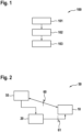
- Fig. 1 shows an embodiment of the inventive method 100 for a Reduced capability user equipment 10.
- Fig. 1 illustrates according to one embodiment of the invention a method 100 for sensing assisted positioning, at a reduced capability user equipment 10, comprising the following steps, which are performed periodically and automatically, wherein the reduced capability user equipment 10 is configured to operate with two frequency ranges 1,2, each with a different bandwidth.
- a first frequency range 1 for transmitting a sensing signal is activated based on a configuration information.
- the sensing signal is transmitted in the first frequency range 1, wherein the sensing signal comprises a sidelink positioning reference signal 7.
- step 103 the reduced capability user equipment 10 switches to the second frequency range 2 for transmitting and/or receiving data after finishing the transmitting 102 of the sensing signal.
- Fig. 2 illustrates a further embodiment of the inventive method 100 for a Reduced capability user equipment 10.
- the Reduced Capability user equipment 10 or RedCap UE 10 can be configured by the cellular network, for example by the node 55 of the cellular network 50. This can be performed by transmitting a configuration information to the RedCap UE 10, wherein the configuration information comprises a bandwidth for the first frequency range 1 in which the reduced capability user equipment 10 should operate.
- the RedCap UE 10 receives the transmitted configuration information from the node 55.
- the first frequency range 1 can be configured as a first bandwidth part such as a full sensing bandwidth part for transmitting sensing and/or positioning reference signals 7.
- the full sensing bandwidth can comprise a bandwidth of at least 20 Mhz for the cellular network 50.
- the configuration information can be transmitted via a cellular network interface such as an U u -interface 60.
- the U u -Interface 60 should be understood as the air interface between a user equipment 20 or a Reduced Capability user equipment 10 and a node 55 or base station 55 or of a cellular network 50, also known as the gNodeB (gNB).
- the U u -interface 60 is responsible for providing wireless communication and data transfer between the UE 10, 20 and the network 50. It is also possible to transmit the configuration information via a different network interface such as a PC5-Interface 61.
- the PC5-interface 61 refers to the interface between two neighbouring user equipment 10, 20 or between a user equipment 10, 20 and a nearby cell in the cellular network 50.
- the PC5-interface 61 is used for direct device-to-device (D2D) communication without relying on the node 55 (gNodeB/gNB) or a core network.
- the Reduced capability user equipment 10 as shown in Fig. 2 comprises a transceiver.
- the transceiver is configured to operate with two frequency ranges 1,2, each with a different bandwidth.
- the RedCap UE 10 can comprise a processor coupled with the transceiver and/or a memory comprising instructions to execute the inventive method.
- Fig. 3 illustrates a further embodiment of the inventive method 100.
- Fig. 3 depicts the operation of the RedCap UE 10 over time regarding the transmitting and/or receiving in the two configured frequency ranges 1,2.
- the first frequency range 1 comprises a bandwidth such as a so-called bandwidth part 1, which is designed to allow a full transmission of a sensing signal comprising several sensing reference signals 7 or positioning reference signals 7 during a time period or duration Ti 3.
- the first frequency range 1 can be configured with a bandwidth of at least 20 MHz.
- the reduced capability user equipment 10 switches to the second frequency range 2 configured for data communication. During this time period or duration T d 4 the user equipment 10 can transmit or to receive data.
- the bandwidth of the second frequency range 2 is smaller than the bandwidth of the first frequency range 1.
- the bandwidth of the second frequency range 2 can be 5 Mhz.
- the user equipment 10 switches periodically and/or automatically to the first or second frequency range 1,2.
- the configuration information of the first frequency range 1 or the first bandwidth part 1 should contain a frequency information regarding the first frequency range 1 comprising for example a bandwidth of 20 Mhz or 100 Mhz. Further, it can comprise an allocation information regarding the carrier frequency, and/or a number of subchannels and/or physical resource blocks or other relevant information for configuring the first frequency range 1 or the second frequency range 2. Furthermore, the configuration information can also comprise a time information for the duration of the sensing impulse measured in the number of signals or symbols during the duration T i 3. Optionally, the configuration information can contain a pattern of the positioning reference signals 7 or the sensing reference signal 7.
- Fig. 4 shows a further embodiment of the inventive method 100.
- Fig. 4 illustrates a further embodiment of the operation of the RedCap UE 10 over time regarding the transmitting and/or receiving in the two configured frequency ranges 1,2.
- this embodiment is similar to the embodiment in Fig. 3 .
- the first frequency range 1 and the duration of the sensing signal have a time-frequency duality relationship in this embodiment.
- This duality means that the larger the first frequency range 1 is the shorter is the duration T i 3 of the sensing signal comprising the positioning or sensing reference symbols 7.
- a silent time period or duration T s 6 can be implemented after the transmission period T i 3 or the duration T i 3 of an activated first frequency range 1.
- the configuration information can comprise for example that as a first option the first frequency range 1 can be different from the second frequency range2 ; for example, the first frequency range 1 can be chosen as Frequency Range FR2, FR3 or FR4 according to the 5G NR standards, while the second frequency range 2 can be FR1.
- a second option can be that a subcarrier spacing (SCS) of the first frequency range 1 can be different from the subcarrier spacing of the second frequency range 2.
- SCS subcarrier spacing
- the first frequency range 1 can contain a subcarrier spacing of 60 or 120 kHz
- the second frequency range 2 can contain a subcarrier spacing of 15 or 30 kHz.
- FR1, FR2, FR3, and FR4 are used to classify different frequency ranges.
- FR1 or Frequency Range 1 provides a frequency range from 450 MHz to 6000 MHz.
- FR2 or Frequency Range 2 provides a frequency range from 24250 MHz to 52600 MHz.
- FR2 provides a higher bandwidth and enables extremely high data transfer rates. Frequency bands such as 24 GHz, 28 GHz, 39 GHz, and 47 GHz typically can fall within this range.
- FR3 and FR4 are yet not defined according to the 3GPP standards or have not yet been standardized.
- Fig. 5 illustrates a further embodiment of the inventive method 100.
- Fig. 5 depicts an embodiment illustration a frequency hopping approach regarding the configuration of the first frequency range 1.
- Fig. 5 depicts the transmission of the sensing signal comprising the sensing or positioning reference symbols 7 using frequency hopping on a first frequency range 1.
- the bandwidth of the first frequency range 1 comprises a fixed bandwidth value, wherein the bandwidth is configured to be smaller or equal to the bandwidth of the second frequency range 2.
- the first frequency range 1 can contain a higher subcarrier spacing than the subcarrier spacing of the second frequency range 2.
- Frequency hopping is a method of transmitting radio signals by rapidly changing the carrier frequency among many frequencies occupying a large frequency band.
Landscapes
- Engineering & Computer Science (AREA)
- Signal Processing (AREA)
- Computer Networks & Wireless Communication (AREA)
- Mobile Radio Communication Systems (AREA)
Priority Applications (3)
| Application Number | Priority Date | Filing Date | Title |
|---|---|---|---|
| EP23189381.9A EP4503680A1 (de) | 2023-08-03 | 2023-08-03 | Verfahren zur erfassung von unterstützter positionierung |
| PCT/EP2024/071857 WO2025027148A1 (en) | 2023-08-03 | 2024-08-01 | A method for sensing assisted positioning |
| CN202480050480.4A CN121620939A (zh) | 2023-08-03 | 2024-08-01 | 用于感测辅助定位的方法 |
Applications Claiming Priority (1)
| Application Number | Priority Date | Filing Date | Title |
|---|---|---|---|
| EP23189381.9A EP4503680A1 (de) | 2023-08-03 | 2023-08-03 | Verfahren zur erfassung von unterstützter positionierung |
Publications (1)
| Publication Number | Publication Date |
|---|---|
| EP4503680A1 true EP4503680A1 (de) | 2025-02-05 |
Family
ID=87556430
Family Applications (1)
| Application Number | Title | Priority Date | Filing Date |
|---|---|---|---|
| EP23189381.9A Withdrawn EP4503680A1 (de) | 2023-08-03 | 2023-08-03 | Verfahren zur erfassung von unterstützter positionierung |
Country Status (3)
| Country | Link |
|---|---|
| EP (1) | EP4503680A1 (de) |
| CN (1) | CN121620939A (de) |
| WO (1) | WO2025027148A1 (de) |
Citations (3)
| Publication number | Priority date | Publication date | Assignee | Title |
|---|---|---|---|---|
| US20210185632A1 (en) * | 2019-12-16 | 2021-06-17 | Qualcomm Incorporated | Signaling details for prs stitching for positioning in a wireless network |
| US20230084636A1 (en) * | 2021-09-14 | 2023-03-16 | Qualcomm Incorporated | Sidelink reference signal configuration |
| US20230223984A1 (en) * | 2020-08-19 | 2023-07-13 | Qualcomm Incorporated | Frequency hopping scheme with partial inter-hop bandwidth overlap |
-
2023
- 2023-08-03 EP EP23189381.9A patent/EP4503680A1/de not_active Withdrawn
-
2024
- 2024-08-01 CN CN202480050480.4A patent/CN121620939A/zh active Pending
- 2024-08-01 WO PCT/EP2024/071857 patent/WO2025027148A1/en active Pending
Patent Citations (3)
| Publication number | Priority date | Publication date | Assignee | Title |
|---|---|---|---|---|
| US20210185632A1 (en) * | 2019-12-16 | 2021-06-17 | Qualcomm Incorporated | Signaling details for prs stitching for positioning in a wireless network |
| US20230223984A1 (en) * | 2020-08-19 | 2023-07-13 | Qualcomm Incorporated | Frequency hopping scheme with partial inter-hop bandwidth overlap |
| US20230084636A1 (en) * | 2021-09-14 | 2023-03-16 | Qualcomm Incorporated | Sidelink reference signal configuration |
Also Published As
| Publication number | Publication date |
|---|---|
| CN121620939A (zh) | 2026-03-06 |
| WO2025027148A1 (en) | 2025-02-06 |
Similar Documents
| Publication | Publication Date | Title |
|---|---|---|
| EP3206448B1 (de) | Verfahren und vorrichtung zur konfiguration einer zelle in einem drahtloskommunikationssystem | |
| CN108809370B (zh) | 用于使用无线网络中的多个频带进行通信的系统 | |
| KR102487332B1 (ko) | 신호 전송 방법, 네트워크 기기 및 단말 기기 | |
| CN115702589B (zh) | 同步信号块的传输方法、装置、设备及存储介质 | |
| CN108811155B (zh) | 随机接入方法、网络设备和终端设备 | |
| EP4734627A1 (de) | Verfahren und vorrichtung zur sidelink-kommunikation | |
| EP3179778B1 (de) | Verfahren und vorrichtung zur meldung und verarbeitung von proximitätsdienstkapazitätsinformation | |
| EP3637894B1 (de) | Datenübertragungsverfahren, endgerätevorrichtung und netzwerkvorrichtung | |
| US10439672B2 (en) | Methods for signaling or receiving cell identity, network identity, and frequency hopping patterns | |
| CN114765786B (zh) | 同步信号块参数确定方法及相关装置 | |
| EP3498000B1 (de) | Zweistufige mrs-konfiguration | |
| KR20200082230A (ko) | 자원 관리를 위한 장치 및 방법 | |
| CN119095165A (zh) | 无线通信的方法、终端设备和网络设备 | |
| US20150215855A1 (en) | Apparatus for cell specific reference signal transmission on lte small cell | |
| EP4734643A1 (de) | Verfahren und vorrichtung zur sidelink-kommunikation | |
| WO2023071968A1 (zh) | 一种通信的方法和通信装置 | |
| AU2018407271A1 (en) | Channel transmission method and apparatus, and computer storage medium | |
| EP3610677A1 (de) | Drahtloskommunikationsvorrichtung, netzwerkknoten, verfahren und computerprogramme | |
| EP4503680A1 (de) | Verfahren zur erfassung von unterstützter positionierung | |
| US11758495B2 (en) | Signal transmission method and apparatus and computer storage medium | |
| CN117730605B (zh) | 用于侧行通信的方法及装置 | |
| RU2774411C1 (ru) | Способы, оборудование и системы для передачи информации сигналов и каналов | |
| KR20250056065A (ko) | 자원을 할당하기 위한 장치 및 방법 | |
| WO2018042373A2 (en) | Methods for signaling or receiving cell identity, network identity, and time hopping patterns |
Legal Events
| Date | Code | Title | Description |
|---|---|---|---|
| PUAI | Public reference made under article 153(3) epc to a published international application that has entered the european phase |
Free format text: ORIGINAL CODE: 0009012 |
|
| STAA | Information on the status of an ep patent application or granted ep patent |
Free format text: STATUS: THE APPLICATION HAS BEEN PUBLISHED |
|
| AK | Designated contracting states |
Kind code of ref document: A1 Designated state(s): AL AT BE BG CH CY CZ DE DK EE ES FI FR GB GR HR HU IE IS IT LI LT LU LV MC ME MK MT NL NO PL PT RO RS SE SI SK SM TR |
|
| STAA | Information on the status of an ep patent application or granted ep patent |
Free format text: STATUS: REQUEST FOR EXAMINATION WAS MADE |
|
| 17P | Request for examination filed |
Effective date: 20250805 |
|
| STAA | Information on the status of an ep patent application or granted ep patent |
Free format text: STATUS: THE APPLICATION IS DEEMED TO BE WITHDRAWN |
|
| 18D | Application deemed to be withdrawn |
Effective date: 20250806 |