EP4503793A1 - Procédé d'indication de port dmrs et appareil associé - Google Patents
Procédé d'indication de port dmrs et appareil associé Download PDFInfo
- Publication number
- EP4503793A1 EP4503793A1 EP22932687.1A EP22932687A EP4503793A1 EP 4503793 A1 EP4503793 A1 EP 4503793A1 EP 22932687 A EP22932687 A EP 22932687A EP 4503793 A1 EP4503793 A1 EP 4503793A1
- Authority
- EP
- European Patent Office
- Prior art keywords
- dmrs
- dmrs port
- port configuration
- configuration table
- data transmission
- Prior art date
- Legal status (The legal status is an assumption and is not a legal conclusion. Google has not performed a legal analysis and makes no representation as to the accuracy of the status listed.)
- Pending
Links
Images


Classifications
-
- H—ELECTRICITY
- H04—ELECTRIC COMMUNICATION TECHNIQUE
- H04L—TRANSMISSION OF DIGITAL INFORMATION, e.g. TELEGRAPHIC COMMUNICATION
- H04L5/00—Arrangements affording multiple use of the transmission path
- H04L5/003—Arrangements for allocating sub-channels of the transmission path
- H04L5/0048—Allocation of pilot signals, i.e. of signals known to the receiver
- H04L5/0051—Allocation of pilot signals, i.e. of signals known to the receiver of dedicated pilots, i.e. pilots destined for a single user or terminal
-
- H—ELECTRICITY
- H04—ELECTRIC COMMUNICATION TECHNIQUE
- H04L—TRANSMISSION OF DIGITAL INFORMATION, e.g. TELEGRAPHIC COMMUNICATION
- H04L5/00—Arrangements affording multiple use of the transmission path
- H04L5/0091—Signalling for the administration of the divided path, e.g. signalling of configuration information
- H04L5/0094—Indication of how sub-channels of the path are allocated
-
- H—ELECTRICITY
- H04—ELECTRIC COMMUNICATION TECHNIQUE
- H04W—WIRELESS COMMUNICATION NETWORKS
- H04W56/00—Synchronisation arrangements
- H04W56/001—Synchronization between nodes
- H04W56/0015—Synchronization between nodes one node acting as a reference for the others
-
- H—ELECTRICITY
- H04—ELECTRIC COMMUNICATION TECHNIQUE
- H04W—WIRELESS COMMUNICATION NETWORKS
- H04W72/00—Local resource management
- H04W72/20—Control channels or signalling for resource management
- H04W72/21—Control channels or signalling for resource management in the uplink direction of a wireless link, i.e. towards the network
-
- H—ELECTRICITY
- H04—ELECTRIC COMMUNICATION TECHNIQUE
- H04W—WIRELESS COMMUNICATION NETWORKS
- H04W72/00—Local resource management
- H04W72/20—Control channels or signalling for resource management
- H04W72/23—Control channels or signalling for resource management in the downlink direction of a wireless link, i.e. towards a terminal
- H04W72/232—Control channels or signalling for resource management in the downlink direction of a wireless link, i.e. towards a terminal the control data signalling from the physical layer, e.g. DCI signalling
Definitions
- the present application relates to the field of communication technologies, and more particularly, to a method and an apparatus for indicating a demodulation reference signal (DMRS) port.
- DMRS demodulation reference signal
- the number of uplink transmission layers of a terminal can be increased to eight layers for supporting a higher uplink transmission rate comparable to a downlink transmission rate.
- the issue of how to realize DMRS port allocation for the single user multiple input multiple output (SU-MIMO) supporting up to eight uplink transmission layers under an enhanced cyclic prefix orthogonal frequency division multiplexing (CP-OFDM) waveform remains unsolved.
- Embodiments of the present application provide a method and an apparatus for indicating a demodulation reference signal (DMRS) port, which may solve a problem of allocating a DMRS port to a single terminal when uplink transmission layers of the terminal is increased to eight layers.
- DMRS demodulation reference signal
- an embodiment of the present application discloses a method for indicating a DMRS port which is applicable to a network device, and the method includes: in response to a maximum number N of uplink data transmission layers corresponding to a physical uplink shared channel (PUSCH) transmission supported by a single terminal being equal to eight, determining a DMRS port configuration table for a first uplink data transmission layer based on a DMRS type parameter, in which the DMRS port configuration table includes a DMRS port allocation set defined for the first uplink data transmission layer; and indicating, based on the DMRS port configuration table, one or more DMRS ports allocated for the PUSCH transmission to the terminal.
- PUSCH physical uplink shared channel
- the embodiments of the present application provide a method for indicating a DMRS port, when the maximum number of uplink data transmission layers supported by the single terminal is eight, the DMRS port configuration table is configured for the first uplink data transmission layer based on a DMRS type, and one or more required DMRS ports are allocated for the PUSCH transmission based on the configured DMRS port configuration table.
- a plurality of configuration modes for configuring the DMRS port configuration table for a newly added uplink data transmission layer are provided, and a blank space of configuring the required DMRS port configuration table for the newly added uplink data transmission layer is filled, so as to provide a basis for enhancing an uplink sending capability.
- the terminal can be allocated with the required DMRS port for the PUSCH transmission based on the configured DMRS port configuration table, which is beneficial to avoid the conflict between the PUSCH and the DMRSs of other scheduled terminal.
- an embodiment of the present application provides a method for indicating a DMRS port, the method is applicable to a terminal, and the method includes: in response to a maximum number N of uplink data transmission layers corresponding to a physical uplink shared channel (PUSCH) transmission supported by the terminal being equal to eight, determining a DMRS port configuration table for a first uplink data transmission layer based on a DMRS type parameter, in which the DMRS port configuration table includes a DMRS port allocation set defined for the first uplink data transmission layer; and receiving indication information sent by a network device, and acquiring, based on the indication information, one or more DMRS ports allocated for the PUSCH transmission of the terminal from the DMRS port configuration table.
- PUSCH physical uplink shared channel
- the DMRS port configuration table is configured for the first uplink data transmission layer based on a DMRS type, and one or more required DMRS ports are allocated for the PUSCH transmission based on the configured DMRS port configuration table.
- a plurality of configuration modes for configuring the DMRS port configuration table for a newly added uplink data transmission layer are provided, and a blank space of configuring the required DMRS port configuration table for the newly added uplink data transmission layer is filled, so as to provide a basis for enhancing an uplink sending capability.
- the terminal can be allocated with the required DMRS port for the PUSCH transmission based on the configured DMRS port configuration table, which is beneficial to avoid the conflict between the PUSCH and the DMRSs of other scheduled terminal.
- an embodiment of the present application provides a communication apparatus which has some or all of functions of the network device in the method example described in the above-mentioned first aspect, for example, the functions of the communication apparatus may have the functions in some or all of the embodiments of the present application, or may have the functions for separately implementing any of the embodiments of the present application.
- the functions may be implemented by hardware, or may be implemented by hardware executing corresponding software.
- the hardware or software includes one or more units or modules corresponding to the functions described above.
- the structure of the communication apparatus may include a transceiver module, and a processing module configured to support the communication apparatus to perform corresponding functions of the method described above.
- the transceiver module is used for supporting communication between the communication apparatus and other devices.
- the communication apparatus may further include a storage module for coupling with the transceiver module and the processing module, which stores computer programs and data necessary for the communication apparatus.
- the processing module may be a processor
- the transceiver module may be a transceiver or a communication interface
- the storage module may be a memory
- an embodiment of the present application provides another communication apparatus which has some or all of functions of the terminal in the method example described in the above-mentioned second aspect, for example, the functions of the communication apparatus may have the functions in some or all of the embodiments of the present application, or may have the functions for separately implementing any of the embodiments of the present application.
- the functions may be implemented by hardware, or may be implemented by hardware executing corresponding software.
- the hardware or software includes one or more units or modules corresponding to the functions described above.
- the structure of the communication apparatus may include a transceiver module, and a processing module configured to support the communication apparatus to perform corresponding functions of the method described above.
- the transceiver module is used for supporting communication between the communication apparatus and other devices.
- the communication apparatus may further include a storage module for coupling with the transceiver module and the processing module, which stores computer programs and data necessary for the communication apparatus.
- the processing module may be a processor
- the transceiver module may be a transceiver or a communication interface
- the storage module may be a memory
- an embodiment of the present application provides a communication apparatus, the communication apparatus includes a processor which, when calling a computer program in a memory, executes the method in the above-mentioned first aspect.
- an embodiment of the present application provides a communication apparatus, the communication apparatus includes a processor which, when calling a computer program in a memory, executes the method in the above-mentioned second aspect.
- an embodiment of the present application provides a communication apparatus, the communication apparatus includes a processor and a memory, the memory stores a computer program, and the processor executes the computer program stored in the memory, such that the communication apparatus executes the method in the above-mentioned first aspect.
- an embodiment of the present application provides a communication apparatus, the communication apparatus includes a processor and a memory, the memory stores a computer program, and the processor executes the computer program stored in the memory, such that the communication apparatus executes the method in the above-mentioned second aspect.
- an embodiment of the present application provides a communication apparatus, the apparatus includes a processor and an interface circuit, the interface circuit is used for receiving code instructions and transmitting the code instructions to the processor, and the processor is used for running the code instructions, such that the apparatus executes the method in the above-mentioned first aspect.
- an embodiment of the present application provides a communication apparatus, the apparatus includes a processor and an interface circuit, the interface circuit is used for receiving code instructions and transmitting the code instructions to the processor, and the processor is used for running the code instructions, such that the apparatus executes the method in the above-mentioned second aspect.
- an embodiment of the present application provides a computer-readable storage medium used for storing instructions used by the above-mentioned receiving device, and the instructions, when executed, enable the receiving device to execute the method in the above-mentioned first aspect.
- an embodiment of the present application provides a readable storage medium used for storing instructions used by the above-mentioned transmitting device, and the instructions, when executed, enable the transmitting device to execute the method in the above-mentioned second aspect.
- first, second, third, etc. may be used in describing various information in embodiments of the present disclosure, such information should not be limited to these terms. These terms are only used to distinguish one type of information from another. For example, first information may also be referred to as second information, and similarly, second information may also be referred to as first information, without departing from the scope of embodiments of the present disclosure. According to the context, the word “if” as used herein may be interpreted as "when” or “while” or "in response to a determining”.
- the terms “greater than” or “less than”, “higher than” or “lower than” are used herein when characterizing size relationships. However, for a person skilled in the art, it can be understood that: the term “greater than” also encompasses the meaning of “greater than or equal to”, and “less than” also encompasses the meaning of “less than or equal to”; the term “higher than” encompasses the meaning of “higher than equal to” and “lower than” encompasses the meaning of "lower than equal to”.
- DMRS Demodulation Reference Signal
- DMRS is a demodulation reference signal used for channel estimation and associated demodulation of a physical channel, and the DMRS can be mapped to physical channels such as Physical Broadcast Channel (PBCH), Physical Downlink Control Channel (PDCCH,) Physical Downlink Shared Channel (PDSCH), Physical Uplink Control Channel (PUCCH) and Physical Uplink Shared Channel (PUSCH).
- PBCH Physical Broadcast Channel
- PDCCH Physical Downlink Control Channel
- PDSCH Physical Downlink Shared Channel
- PUCCH Physical Uplink Control Channel
- PUSCH Physical Uplink Control Channel
- PUSCH Physical Uplink Shared Channel
- a DMRS structure combining the front-load DMRS with an additional DMRS whose time density is configurable is adopted.
- the accuracy of channel estimation can be improved by configuring the additional DMRS.
- up to three groups of additional DMRSs can be configured for each scheduling.
- DMRS patterns are classified into two types, including type 1 and type 2, and a length of OFDM symbols occupied by the DMRS of each type can be 1 or 2.
- a network device When scheduling data, such as scheduling data of the physical uplink shared channel (PUSCH), a network device needs to indicate a corresponding DMRS port, including the number of DMRS ports and a port number of each DMRS port. Physical resources occupied by different DMRS ports corresponding to a same DMRS port number are orthogonal; and the physical resources include one or more of spatial resources, time domain resources and frequency domain resources.
- PUSCH physical uplink shared channel
- the DMRS design principles of the data channel (PDSCH/PUSCH) in the NR system mainly include the following aspects:
- the pattern design of the front-load DMRS is a basis for the DMRS design.
- the design ideas of the front-load DMRS can be classified into two types, the first type (type1) adopts COMB+OCC structure, and the second type (type2) is based on FDM+OCC structure.
- the front-load DMRS can be configured as up to two OFDM symbols.
- TD-OCC is used in the time domain based on CS or OCC in the frequency domain when the front-load DMRS of two symbols is used.
- the NR system adopts a DMRS structure combining the front-load DMRS and the additional DMRS whose time density is configurable.
- the pattern for each group of additional DMRS is a repetition of that the front-load DMRS.
- each group of additional DMRS can also occupy up to two consecutive DMRS symbols.
- up to three groups of additional DMRSs can be configured for each scheduling. The number of additional DMRSs depends on a higher layer parameter configuration and the specific scheduling duration.
- a current protocol can only support up to four uplink transmission layers, while can support up to eight downlink layers. However, in the future, the uplink enhancement resulting in up to eight transmitting antennas will be included to support a higher uplink transmission rate comparable to the downlink transmission rate.
- the uplink supports DMRS port allocation of a maximum of four layers, which cannot support coherent demodulation of a higher RANK under SU, so that there is a need of DMRS port allocation for the SU-MIMO supporting up to eight uplink transmission layers under the enhanced CP-OFDM waveform.
- Embodiments of the present application provide a communication system that may include, but is not limited to, a transmitting device and a receiving device.
- the transmitting device may be a terminal and the receiving device may be a network device.
- FIG 1 is a schematic diagram of an architecture of a communication system provided in an embodiment of the present application.
- This communication system can include, but is not limited to a network device and a terminal, the number and form of devices shown in FIG 1 are only intended to illustrate, rather than to constitute limitations on the embodiments of the present application. In actual applications, two or more network devices and two or more terminals can be included.
- the communication system shown in FIG 1 is illustrated to include one network device 11 and one terminal 12.
- LTE long term evolution
- 5G 5th generation
- NR 5G new radio
- the network device 11 in the embodiment of the present application is an entity for transmitting or receiving signals at a network side.
- the network device 11 can be an evolved NodeB (eNB), a transmission reception point (TRP), a next generation NodeB (gNB) in the NR system, a base station in other future mobile communication systems or an access point in a wireless fidelity (WiFi) system, etc.
- eNB evolved NodeB
- TRP transmission reception point
- gNB next generation NodeB
- WiFi wireless fidelity
- a specific technology and a specific device form that are adopted by the network device are not limited.
- the network device provided in the embodiment of the present application can be composed of a central unit (CU) and a distributed unit (DU), and the CU can also be referred to as a control unit, the protocol layer of the network device, such as a base station, can be split by adopting a CU-DU structure, parts of functions of the protocol layer are centrally controlled by the CU, and parts or all of remaining functions of the protocol layer are distributed in the DU, and the DU is centrally controlled by the CU.
- the protocol layer of the network device such as a base station
- the terminal 12 in the embodiment of the present application is an entity, such as a mobile phone, for receiving or transmitting signals.
- the terminal can also be referred to as a terminal, user equipment (UE), a mobile station (MS), a mobile terminal (MT), etc.
- the terminal can be a car with a communication function, a smart car, a mobile phone, an internet of things device such as an NB-IoT or (e)MTC, a wearable device, a tablet computer (Pad), a computer with a radio transceiver function, a virtual reality (VR) terminal, an augmented reality (AR) terminal, a radio terminal in industrial control, a radio terminal in self-driving, a radio terminal in remote medical surgery, a radio terminal in a smart grid, a radio terminal in transportation safety, a radio terminal in a smart city, a radio terminal in a smart home, etc.
- a specific technology and a specific device form that are adopted by the terminal are not limited.
- FIG 2 is a schematic flowchart of a method for indicating a DMRS port provided by an embodiment of the present application. As shown in FIG 2 , the method is performed by a network device, and may include, but is not limited to, the following steps.
- a DMRS port configuration table is determined for a first uplink data transmission layer based on a DMRS type parameter and a number of second uplink data transmission layers.
- the first uplink data transmission layer refers to a newly added uplink data transmission layer on a basis of the uplink data transmission layers corresponding to the PUSCH transmission originally supported by the single terminal.
- the original uplink data transmission layers corresponding to the PUSCH are layers 1-4, and are newly added to eight layers, namely, the first uplink transmission layers may be layers 5-8.
- An original uplink data transmission layer corresponding to the PUSCH can be referred to as a second uplink data transmission layer, namely, the second uplink data transmission layers may be layers 1-4. This definition applies to all embodiments of the present disclosure.
- the uplink data transmission layers include the newly added first uplink data transmission layers and the original second uplink data transmission layers.
- RI RANK Indicator
- the DMRS type parameter may include a DMRS type, or a DMRS type and a maximum number of symbols of a front-load DMRS.
- the DMRS type includes type 1 and type 2, and the maximum number of symbols of the front-load DMRS includes 1 or 2.
- a DMRS port allocation set defined for the first uplink data transmission layer is included in the DMRS port configuration table.
- the DMRS port allocation set includes one DMRS port or a plurality of DMRS ports available for the first uplink data transmission layer.
- one or more parameters of the DMRS type parameter may also be included in the DMRS port configuration table, for example, the DMRS type can be included, or the maximum number of symbols of the front-load DMRS can be included, or the DMRS type and the maximum number of symbols of the front-load DMRS can be included.
- the DMRS port configuration table may also include a quantity of code division multiplexings (CDMs) that do not carry data.
- CDMs code division multiplexings
- the number of table rows, i.e. the value of the row, in the DMRS port configuration table may be used to index to one or more DMRS ports.
- first DMRS port configuration tables respectively corresponding to different DMRS type parameters may be generated for the first uplink data transmission layer. That is, for each first uplink data transmission layer, a plurality of first DMRS port configuration tables may be configured, in which each first DMRS port configuration table corresponds to one DMRS type parameter.
- the network device cannot configure the DMRS port allocation table for the first uplink transmission layers, namely, layers 5-8.
- a total number of first DMRS port configuration tables is ten.
- the network device cannot configure the DMRS port allocation table for the first uplink transmission layers, namely, layers 5-8, and therefore a total number of the second DMRS port configuration tables is three.
- the DMRS port indication field in the DCI can be indicated by 4 bits.
- DCI0-1/0-2 may be employed to indicate the ports to the terminal.
- the third DMRS port configuration table is shown in Table 6 below: Table 6 Two Codewords 0 indicates enabled, while 1 indicates disabled Row No. (Value) DMRS type DMRS CDM group not carrying data DMRS port number Maximum number of symbols of the front-load DMRS 0 1 2 0, 1, 2, 3, 4 2 1 1 2 0, 1, 2, 3, 4,6 2 2 1 2 0, 1, 2, 3, 4, 5, 6 2 3 1 2 0, 1, 2, 3, 4, 5, 6, 7 2 4 1 reserved reserved reserved reserved 5 6 7 8 2 3 0, 1, 2, 3, 4 1 9 2 3 0, 1, 2, 3, 4,5 1 10 2 reserved reserved reserved reserved ... ...
- the total number of entries included in the third DMRS port configuration table is thirty two.
- the DMRS port indication field in the DCI can be indicated by 8 bits.
- DCI0-1/0-2 may be employed to indicate the ports to the terminal.
- step S22 based on the DMRS port configuration table, one or more DMRS ports allocated for the PUSCH transmission are indicated to the terminal.
- configuring the DMRS port configuration table for the terminal can include configuring 12 first DMRS port configuration tables, can also include configuring 3 second DMRS port configuration tables, and can also include configuring 1 third DMRS port configuration table.
- One of the above-mentioned implementations may be used by the network device to configure the corresponding DMRS port configuration table for the single terminal.
- the network device can determine the DMRS port allocated for the PUSCH transmission from the DMRS port configuration table based on the DMRS type parameter and the first uplink data transmission layer used by the terminal to perform the PUSCH transmission; optionally, the allocated DMRS ports may include one or multiple DMRS ports, the multiple DMRS ports may be a combination of DMRS ports. That is, one DMRS port or a combination of DMRS ports may be allocated for the PUSCH transmission. Namely, one or more DMRS ports are selected from a predefined DMRS port set corresponding to the used first uplink data transmission layer.
- the DMRS port(s) allocated for the PUSCH transmission is/are indicated to the terminal via a DMRS port indication, so that the terminal uses the one DMRS port or the combination of DMRS ports to perform the PUSCH transmission with the network device.
- the one DMRS port or the combination of DMRS ports allocated for the PUSCH transmission are indicated to the terminal by means of a DMRS port indication field in the downlink control indication (DCI) signaling.
- the DMRS port indication field indicates the number of bits used by the one DMRS port or the combination of DMRS ports, as determined by the number of total entries occupied by the DMRS port configuration table.
- DCI0-1/0-2 may be employed to indicate, to the terminal, the one DMRS port or the combination of DMRS ports allocated for the PUSCH transmission.
- the DMRS port configuration table is configured for the first uplink data transmission layer based on the DMRS type, and one or more required DMRS ports are allocated for the PUSCH transmission based on the configured DMRS port configuration table.
- a plurality of configuration modes for configuring the DMRS port configuration table for a newly added uplink data transmission layer are provided, and a blank space of configuring the required DMRS port configuration table for the newly added uplink data transmission layer is filled, so as to provide a basis for enhancing an uplink sending capability.
- the terminal can be allocated with the required DMRS port for the PUSCH transmission based on the configured DMRS port configuration table, which is beneficial to avoid the conflict between the PUSCH and the DMRSs of other scheduled terminals.
- FIG 3 is a schematic flowchart of a method for indicating a DMRS port provided by an embodiment of the present application. As shown in FIG 3 , the method is performed by a network device, and may include, but is not limited to, the following steps.
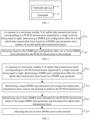
- step S31 in response to a maximum number N of uplink data transmission layers corresponding to a PUSCH transmission supported by a single terminal being equal to eight, a DMRS port configuration table is determined for a first uplink data transmission layer based on a DMRS type parameter.
- the DMRS port allocation set defined for the first uplink data transmission layer is included in the DMRS port configuration table.
- the DMRS port allocation set includes one DMRS port or a plurality of DMRS ports.
- the DMRS port allocation set contains same contents in all embodiments of the present disclosure, i.e. one or more DMRS ports.
- step S31 in the embodiment of the present application can be realized by using any implementation in the various embodiments of the present application, for which the relevant content can be referred to for details, and it will not be described in detail here.
- step S32 a target DMRS type parameter and a target first uplink data transmission layer used by the terminal to perform the PUSCH transmission are determined.
- the DMRS type parameter may include a DMRS type, or a DMRS type and a maximum number of symbols of a front-load DMRS.
- the DMRS type includes type 1 and type 2, and the maximum number of symbols of the front-load DMRS includes 1 or 2.
- the network device may explicitly or implicitly determine the target DMRS type parameter and the target first uplink data transmission layer used by the terminal to perform the PUSCH transmission, which may be, for example, based on protocol agreements or upper layer indications.
- the network device may explicitly or implicitly indicate the target DMRS type parameter and the target first uplink data transmission layer to perform the PUSCH transmission to the terminal.
- step S33 one or more DMRS ports allocated for the PUSCH transmission are determined based on the target DMRS type parameter and the target first uplink data transmission layer.
- the target first DMRS port configuration sub-table can be determined from the multiple second DMRS port configuration tables based on the target DMRS type parameter and the target first uplink data transmission layer.
- DMRS ports 0-4 can be determined as the DMRS ports allocated for the PUSCH transmission.
- a target second DMRS port configuration sub-table or a third DMRS port configuration sub-table can be determined from the third DMRS port configuration table based on the target DMRS type parameter and the target first uplink data transmission layer.
- the DMRS port(s) in the target second DMRS port configuration sub-table is/are determined as one or more DMRS ports allocated for the PUSCH transmission. For example, with reference to table 6, DMRS ports 0-4 can be determined as the DMRS ports allocated for the PUSCH transmission.
- Table 6 DMRS ports 0-4 can be determined as the DMRS ports allocated for the PUSCH transmission.
- step S34 the one or more DMRS ports are indicated to the terminal.
- the one or more DMRS ports allocated for the PUSCH transmission can be indicated to the terminal via the DMRS port indication, so that the terminal uses the one DMRS port or the combination of DMRS ports to perform the PUSCH transmission with the network device.
- the one or multiple DMRS ports allocated for the PUSCH transmission can be indicated to the terminal by means of a DMRS port indication field in the downlink control information (DCI) signaling, in which the multiple DMRS ports can be a combination of DMRS ports.
- DCI01/0-2 may be employed to indicate, to the terminal, the one DMRS port or the combination of ports allocated for the PUSCH transmission.
- the number of bits occupied by the port indication field is agreed by a protocol or configured by the network or agreed by a protocol through the DMRS type parameter.
- the DMRS port indication field indicates the number of bits used by the one or more DMRS ports, as determined by the number of total entries occupied by the DMRS port configuration table.
- the DMRS port configuration table is configured for the first uplink data transmission layer based on a DMRS type, and one or more required DMRS ports are allocated for the PUSCH transmission based on the configured DMRS port configuration table.
- a plurality of configuration modes for configuring the DMRS port configuration table for the first uplink data transmission layer are provided, and a blank space of configuring the required DMRS port configuration table for the first uplink data transmission layer is filled, so as to provide a basis for enhancing an uplink sending capability.
- the terminal can be allocated with the required DMRS port for the PUSCH transmission based on the configured DMRS port configuration table, which is beneficial to avoid the conflict between the PUSCH and the DMRSs of other scheduled terminals.
- FIG 4 is a schematic flowchart of a method for indicating a DMRS port provided by an embodiment of the present application. As shown in FIG 4 , the method is performed by a network device, and may include, but is not limited to, the following steps.
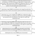
- step S41 in response to a maximum number N of uplink data transmission layers corresponding to a PUSCH transmission supported by a single terminal being equal to eight, a DMRS port configuration table is determined for a first uplink data transmission layer based on a DMRS type parameter and a number of second uplink data transmission layers.
- the DMRS port allocation set defined for the first uplink data transmission layer is included in the DMRS port configuration table.
- first DMRS port configuration tables respectively corresponding to different DMRS type parameters may be generated for the first uplink data transmission layer. That is, each first uplink data transmission layer may be configured with a plurality of first DMRS port configuration tables, in which each first DMRS port configuration table corresponds to one DMRS type parameter.
- a total number of first DMRS port configuration tables is ten.
- step S42 a target DMRS type parameter and a target first uplink data transmission layer used by the terminal to perform the PUSCH transmission are determined.
- step S42 in the embodiment of the present application can be realized by using any implementation in the various embodiments of the present application, for which the relevant content can be referred to for details, and it will not be described in detail here.
- the network device may explicitly or implicitly determine the target DMRS type parameter and the target first uplink data transmission layer used by the terminal to perform the PUSCH transmission, which may be, for example, based on protocol agreements or upper layer indications.
- the network device may explicitly or implicitly indicate the target DMRS type parameter and/or the target first uplink data transmission layer to the terminal.
- step S43 one or more candidate first DMRS port configuration tables are determined from the first DMRS port configuration tables based on the target DMRS type parameter and a first parameter in the target first uplink data transmission layer.
- a target first DMRS port configuration table is determined from the one or more candidate first DMRS port configuration tables based on the target DMRS type parameter and a second parameter in the target first uplink data transmission layer.
- the network device determines, from the first DMRS port configuration table, the first DMRS port configuration tables of different RIs corresponding to the target DMRS type parameter as the candidate first DMRS port configuration tables, when the DMRS type parameter is the target DMRS type parameter.
- the candidate first DMRS port configuration tables include:
- the network device determines the target first DMRS port configuration table from the one or more candidate first DMRS port configuration tables based on the target first uplink data transmission layer.
- the network device determines the first DMRS port configuration tables corresponding to different DMRS type parameters for the target first uplink data transmission layer from the first DMRS port configuration tables as the candidate first DMRS port configuration tables.
- the candidate first DMRS port configuration tables include:
- the network device determines the target first DMRS port configuration table from the candidate first DMRS port configuration tables based on the target DMRS type parameter.
- step S45 one or more DMRS ports allocated for the PUSCH transmission are determined based on the target first DMRS port configuration table.
- the target first DMRS port configuration table is the first DMRS port configuration table 1, with reference to table 1, DMRS ports 0-4 can be determined as the DMRS ports allocated for the PUSCH transmission.
- step S46 the one or more DMRS ports are indicated to the terminal.
- the one or multiple DMRS ports allocated for the PUSCH transmission can be indicated to the terminal by means of a DMRS port indication field in the downlink control information (DCI) signaling.
- DCI downlink control information
- DCI0-1/0-2 may be employed to indicate, to the terminal, the one or multiple DMRS ports allocated for the PUSCH transmission.
- the DMRS port indication field in the DCI includes a port index value for indicating port index values of the one or more DMRS ports.
- the port index value is a row index of one target DMRS port configuration sub-table.
- the port index value is an index offset, and an actual port index value may be determined based on a starting index value and the row offset.
- the one or multiple DMRS ports allocated for the PUSCH transmission are indicated to the terminal via a DMRS port indication field in the DCI, in which the multiple DMRS ports may be a combination of DMRS ports.
- the DMRS port configuration table is configured for the first uplink data transmission layer based on a DMRS type, and one or more required DMRS ports are allocated for the PUSCH transmission based on the configured DMRS port configuration table.
- a plurality of configuration modes for configuring the DMRS port configuration table for the newly added uplink data transmission layer are provided, and a blank space of configuring the required DMRS port configuration table for the newly added uplink data transmission layer is filled, so as to provide a basis for enhancing an uplink sending capability.
- the terminal can be allocated with the required DMRS port for the PUSCH transmission based on the configured DMRS port configuration table, which is beneficial to avoid the conflict between the PUSCH and the DMRSs of other scheduled terminals.
- FIG 5 is a schematic flowchart of a method for indicating a DMRS port provided by an embodiment of the present application. As shown in FIG 5 , the method is performed by a network device, and may include, but is not limited to, the following steps.
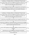
- step S51 in response to a maximum number N of uplink data transmission layers corresponding to a PUSCH transmission supported by a single terminal being equal to eight, a DMRS port configuration table is determined for a first uplink data transmission layer based on a DMRS type parameter and a number of second uplink data transmission layers.
- the DMRS port allocation set defined for the first uplink data transmission layer is included in the DMRS port configuration table.
- a total number of second DMRS port configuration tables is three.
- step S52 a target DMRS type parameter and a target first uplink data transmission layer used by the terminal to perform the PUSCH transmission are determined.
- step S52 in the embodiment of the present application can be realized by using any implementation in the various embodiments of the present application, for which the relevant content can be referred to for details, and it will not be described in detail here.
- the network device may explicitly or implicitly determine the target DMRS type parameter and the target first uplink data transmission layer used by the terminal to perform the PUSCH transmission, which may be, for example, based on protocol agreements or upper layer indications.
- the network device may explicitly or implicitly indicate the target DMRS type parameter and/or the target first uplink data transmission layer to the terminal.
- a candidate second DMRS port configuration table is determined from a second DMRS port configuration table based on the target DMRS type parameter.
- a target first DMRS port configuration sub-table is determined from the candidate second DMRS port configuration table based on the target first uplink data transmission layer.
- the network device determines, from a plurality of configured second DMRS port configuration tables, a second DMRS port configuration table corresponding to the DMRS type parameter being the target DMRS type parameter as the candidate second DMRS port configuration table.
- step S55 one or more DMRS ports allocated for the PUSCH transmission are determined based on the target first DMRS port configuration sub-table.
- the target first DMRS port configuration sub-table After the target first DMRS port configuration sub-table is determined, one or more DMRS ports in the target first DMRS port configuration sub-table are determined as the one or more DMRS ports allocated for the PUSCH transmission.
- the target first DMRS port configuration sub-table is the first DMRS port configuration sub-table 1, with reference to table 5, DMRS ports 0-4 can be determined as the DMRS ports allocated for the PUSCH transmission.
- step S56 the one or more DMRS ports are indicated to the terminal.
- the one or multiple DMRS ports allocated for the PUSCH transmission can be indicated to the terminal by means of a DMRS port indication field in the downlink control information (DCI) signaling.
- the multiple DMRS ports may be a combination of DMRS ports.
- the DMRS port indication field in the DCI includes a port index value for indicating port index values of the one or more DMRS ports.
- the port index value is a row index of one target DMRS port configuration sub-table.
- the port index value is an index offset, and an actual port index value may be determined based on a starting index value and the row offset.
- the DMRS port configuration table is configured for the first uplink data transmission layer based on a DMRS type, and one or more required DMRS ports are allocated for the PUSCH transmission based on the configured DMRS port configuration table.
- a plurality of configuration modes for configuring the DMRS port configuration table for the first uplink data transmission layer are provided, and a blank space of configuring the required DMRS port configuration table for the first uplink data transmission layer is filled, so as to provide a basis for enhancing an uplink sending capability.
- the terminal can be allocated with the required DMRS port for the PUSCH transmission based on the configured DMRS port configuration table, which is beneficial to avoid the conflict between the PUSCH and the DMRSs of other scheduled terminals.
- FIG 6 is a schematic flowchart of a method for indicating a DMRS port provided by an embodiment of the present application. As shown in FIG 6 , the method is performed by a network device, and may include, but is not limited to, the following steps.
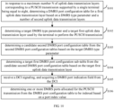
- step S61 in response to a maximum number N of uplink data transmission layers corresponding to a PUSCH transmission supported by a single terminal being equal to eight, a DMRS port configuration table is determined for a first uplink data transmission layer based on a DMRS type parameter and a number of second uplink data transmission layers.
- the DMRS port allocation set defined for the first uplink data transmission layer is included in the DMRS port configuration table.
- the total number of entries included in the third DMRS port configuration table is thirty two.
- step S62 a target DMRS type parameter and a target first uplink data transmission layer used by the terminal to perform the PUSCH transmission are determined.
- step S62 in the embodiment of the present application can be realized by using any implementation in the various embodiments of the present application, for which the relevant content can be referred to for details, and it will not be described in detail here.
- the network device may explicitly or implicitly determine the target DMRS type parameter and the target first uplink data transmission layer used by the terminal to perform the PUSCH transmission, which may be, for example, based on protocol agreements or upper layer indications.
- the network device may explicitly or implicitly indicate the target DMRS type parameter and/or the target first uplink data transmission layer to the terminal.
- a target DMRS port configuration sub-table is determined from the third DMRS port configuration table based on the target DMRS type parameter and the target first uplink data transmission layer.
- the target DMRS port configuration sub-table is one second DMRS port configuration sub-table in the third DMRS port configuration table or is one third DMRS port configuration sub-table in the third DMRS port configuration table.
- a candidate second DMRS port configuration sub-table can be determined from the third DMRS port configuration table based on the target DMRS type parameter as the candidate DMRS port configuration sub-table. Further, a target second DMRS port configuration sub-table is determined from the determined candidate second DMRS port configuration sub-table based on the target first uplink data transmission layer as the target DMRS port configuration sub-table.
- a candidate third DMRS port configuration sub-table can be determined from the third DMRS port configuration table based on the target first uplink data transmission layer as the candidate DMRS port configuration sub-table. Further, a target third DMRS port configuration sub-table is determined from the determined candidate third DMRS port configuration sub-table based on the target DMRS type parameter as the target DMRS port configuration sub-table.
- step S64 one or more DMRS ports allocated for the PUSCH transmission are determined based on the target DMRS port configuration sub-table.
- one or more DMRS ports in the target DMRS port configuration sub-table are determined as the one or more DMRS ports allocated for the PUSCH transmission.
- step S65 the one or more DMRS ports are indicated to the terminal.
- the one or multiple DMRS ports can be indicated to the terminal by means of a DMRS port indication field in the downlink control information (DCI) signaling.
- the multiple DMRS ports may be a combination of DMRS ports.
- the DMRS port indication field in the DCI includes a port index value for indicating port index values of the one or more DMRS ports.
- the port index value is a row index of one target DMRS port configuration sub-table.
- the port index value is an index offset, and an actual port index value may be determined based on a starting index value and the row offset.
- the DMRS port indication field in the DCI can be indicated by 8 bits. That is, when the DMRS port configuration table is the third DMRS port configuration table, the number of bits of the DMRS port indication field is greater than the number of bits used for indicating the one or multiple DMRS ports in the DMRS port configuration table corresponding to the second uplink data transmission layer.
- the DMRS port configuration table is configured for the first uplink data transmission layer based on a DMRS type, and one or more required DMRS ports are allocated for the PUSCH transmission based on the configured DMRS port configuration table.
- a plurality of configuration modes for configuring the DMRS port configuration table for the newly added uplink data transmission layer are provided, and a blank space of configuring the required DMRS port configuration table for the newly added uplink data transmission layer is filled, so as to provide a basis for enhancing an uplink sending capability.
- the terminal can be allocated with the required DMRS port for the PUSCH transmission based on the configured DMRS port configuration table, which is beneficial to avoid the conflict between the PUSCH and the DMRSs of other scheduled terminals.
- FIG 7 is a schematic flowchart of a method for indicating a DMRS port provided by an embodiment of the present application. As shown in FIG 7 , the method is performed by a terminal, and may include, but is not limited to, the following steps.
- step S71 in response to a maximum number N of uplink data transmission layers corresponding to a PUSCH transmission supported by a single terminal being equal to eight, a DMRS port configuration table is determined for a first uplink data transmission layer based on a DMRS type parameter and a number of second uplink data transmission layers.
- the DMRS port allocation set defined for the first uplink data transmission layer is included in the DMRS port configuration table.
- a DMRS port allocation set defined for the first uplink data transmission layer is included in the DMRS port configuration table.
- the DMRS port allocation set includes one DMRS port or multiple DMRS ports available for the first uplink data transmission layer.
- the multiple DMRS ports may be a combination of DMRS ports.
- one or more parameters of the DMRS type parameter may also be included in the DMRS port configuration table, for example, the DMRS type can be included, or the maximum number of symbols of the front-load DMRS can be included, or the DMRS type and the maximum number of symbols of the front-load DMRS can be included.
- the DMRS port configuration table may also include a quantity of code division multiplexings (CDMs) that do not carry data.
- CDMs code division multiplexings
- the number of table rows, i.e. the value of the row, in the DMRS port configuration table may be used to index to one or more DMRS ports.
- first DMRS port configuration tables respectively corresponding to different DMRS type parameters may be generated for the first uplink data transmission layer. That is, for each first uplink data transmission layer, a plurality of first DMRS port configuration tables may be configured, in which each first DMRS port configuration table corresponds to one DMRS type parameter.
- a total number of first DMRS port configuration tables is ten.
- a total number of second DMRS port configuration tables is three.
- the DMRS port indication field in the DCI can be indicated by 4 bits.
- DCI0-1/0-2 may be employed to indicate the ports to the terminal.
- the total number of entries included in the third DMRS port configuration table is thirty two.
- the DMRS port indication field in the DCI can be indicated by 8 bits.
- DCI0-1/0-2 may be employed to indicate the ports to the terminal.
- step S72 indication information sent by a network device is received, and one or more DMRS ports allocated for the PUSCH transmission are acquired from the DMRS port configuration table based on the indication information.
- the network device After determining to allocate one DMRS port or a combination of DMRS ports for the PUSCH transmission, the network device indicates the DMRS port(s) allocated for the PUSCH transmission to the terminal via a DMRS port indication, so that the terminal uses the one DMRS port or the combination of DMRS ports to perform the PUSCH transmission with the network device.
- the network device can indicate, to the terminal, the one DMRS port or the combination of DMRS ports allocated for the PUSCH transmission by means of a DMRS port indication field in the downlink control indication (DCI) signaling.
- the terminal may receive the DCI, obtain the DMRS port indication field from the DCI, and determine the one or more DMRS ports allocated for the PUSCH transmission.
- DCI downlink control indication
- the DMRS port indication field indicates the number of bits used by the one DMRS port or the combination of DMRS ports, as determined by the number of total entries occupied by the DMRS port configuration table.
- DCI0-1/0-2 may be employed to indicate, to the terminal, the one DMRS port or the combination of DMRS ports allocated for the PUSCH transmission.
- the DMRS port configuration table is configured for the first uplink data transmission layer based on the DMRS type, and one or more required DMRS ports are allocated for the PUSCH transmission based on the configured DMRS port configuration table.
- a plurality of configuration modes for configuring the DMRS port configuration table for a newly added uplink data transmission layer are provided, and a blank space of configuring the required DMRS port configuration table for the newly added uplink data transmission layer is filled, so as to provide a basis for enhancing an uplink sending capability.
- the terminal can be allocated with the required DMRS port for the PUSCH transmission based on the configured DMRS port configuration table, which is beneficial to avoid the conflict between the PUSCH and the DMRSs of other scheduled terminals.
- FIG 8 is a schematic flowchart of a method for indicating a DMRS port provided by an embodiment of the present application. As shown in FIG 8 , the method is performed by a terminal, and may include, but is not limited to, the following steps.
- step S81 in response to a maximum number N of uplink data transmission layers corresponding to a PUSCH transmission supported by a single terminal being equal to eight, a DMRS port configuration table is determined for a first uplink data transmission layer based on a DMRS type parameter and a second uplink data transmission layer.
- the DMRS port allocation set defined for the first uplink data transmission layer is included in the DMRS port configuration table.
- step S31 in the embodiment of the present application can be realized by using any implementation in the various embodiments of the present application, for which the relevant content can be referred to for details, and it will not be described in detail here.
- step S82 a target DMRS type parameter and a target first uplink data transmission layer used by the terminal to perform the PUSCH transmission are determined.
- the terminal may explicitly or implicitly determine the target DMRS type parameter and the target first uplink data transmission layer used to perform the PUSCH transmission.
- step S83 a DMRS port configuration table to be indexed is determined from the DMRS port configuration table based on the target DMRS type parameter and the target first uplink data transmission layer
- the DMRS port configuration table is a first DMRS port configuration table, since there are multiple first DMRS port configuration tables, a target first DMRS port configuration table can be determined from the multiple first DMRS port configuration tables based on the target DMRS type parameter and the target first uplink data transmission layer as the DMRS port configuration table to be indexed.
- the target first DMRS port configuration sub-table can be determined from the multiple second DMRS port configuration tables based on the target DMRS type parameter and the target first uplink data transmission layer as the DMRS port configuration table to be indexed.
- a target second DMRS port configuration sub-table or a third DMRS port configuration sub-table can be determined from the third DMRS port configuration table based on the target DMRS type parameter and the target first uplink data transmission layer as the DMRS port configuration table to be indexed.
- a second DMRS port configuration sub-table can be determined from the third DMRS port configuration table as the DMRS port configuration table to be indexed.
- a third DMRS port configuration sub-table can be determined from the third DMRS port configuration table as the DMRS port configuration table to be indexed.
- step S84 a downlink control information (DCI) signaling is received, and a DMRS port indication field is acquired from the DCI.
- DCI downlink control information
- the port indication field includes a port index value, and the port index value is used for indexing one or more DMRS ports allocated for the PUSCH transmission.
- the one DMRS port or the combination of ports allocated for the PUSCH transmission are indicated to the terminal by means of the DMRS port indication field in the DCI.
- DCI0-1/0-2 may be employed to indicate, to the terminal, the one DMRS port or the combination of ports allocated for the PUSCH transmission.
- the number of bits occupied by the port indication field is agreed by a protocol or configured by the network or agreed by a protocol through the DMRS type parameter.
- the DMRS port indication field indicates the number of bits used by the one or more DMRS ports, as determined by the number of total entries occupied by the DMRS port configuration table.
- step S85 one or more DMRS ports allocated for the PUSCH transmission are determined from the DMRS port configuration table to be indexed based on the port index value.
- the port index value is obtained and one DMRS port or the combination of ports allocated for the PUSCH transmission can be determined from the DMRS port configuration table to be indexed.
- indexing is performed on the DMRS port configuration table to be indexed based on a port index value to determine the one DMRS port or the combination of ports therefrom; optionally, in other implementations, a starting index value of a predefined table is determined, an actual port index value is determined according to the port index value and the starting index value, and the one DMRS port or the combination of ports is determined by performing indexing on the DMRS port configuration table to be indexed based on the actual port index value.
- the DMRS port configuration table is configured for the first uplink data transmission layer based on a DMRS type, and one or more required DMRS ports are allocated for the PUSCH transmission based on the configured DMRS port configuration table.
- a plurality of configuration modes for configuring the DMRS port configuration table for the newly added uplink data transmission layer are provided, and a blank space of configuring the required DMRS port configuration table for the newly added uplink data transmission layer is filled, so as to provide a basis for enhancing an uplink sending capability.
- the terminal can be allocated with the required DMRS port for the PUSCH transmission based on the configured DMRS port configuration table, which is beneficial to avoid the conflict between the PUSCH and the DMRSs of other scheduled terminals.
- FIG 9 is a schematic flowchart of a method for indicating a DMRS port provided by an embodiment of the present application. As shown in FIG 9 , the method is performed by a terminal, and may include, but is not limited to, the following steps.
- step S91 in response to a maximum number N of uplink data transmission layers corresponding to a PUSCH transmission supported by a single terminal being equal to eight, a DMRS port configuration table is determined for a first uplink data transmission layer based on a DMRS type parameter and a number of second uplink data transmission layers.
- the DMRS port allocation set defined for the first uplink data transmission layer is included in the DMRS port configuration table.
- each first uplink data transmission layer, first DMRS port configuration tables respectively corresponding to different DMRS type parameters may be generated for the first uplink data transmission layer. That is, each first uplink data transmission layer may be configured with a plurality of first DMRS port configuration tables, in which each first DMRS port configuration table corresponds to one DMRS type parameter.
- a total number of first DMRS port configuration tables is ten.
- step S92 a target DMRS type parameter and a target first uplink data transmission layer used by the terminal to perform the PUSCH transmission are determined.
- step S92 in the embodiment of the present application can be realized by using any implementation in the various embodiments of the present application, for which the relevant content can be referred to for details, and it will not be described in detail here.
- step S93 one or more candidate first DMRS port configuration tables are determined from the first DMRS port configuration tables based on the target DMRS type parameter and a first parameter in the target first uplink data transmission layer.
- a target first DMRS port configuration table is determined from the one or more candidate first DMRS port configuration tables based on the target DMRS type parameter and a second parameter in the target first uplink data transmission layer as a DMRS port configuration table to be indexed.
- the terminal determines, from the first DMRS port configuration table, the first DMRS port configuration tables of different RIs corresponding to the DMRS type parameter being the target DMRS type parameter as the one or more candidate first DMRS port configuration tables. Further, the terminal determines the target first DMRS port configuration table from the one or more candidate first DMRS port configuration tables based on the target first uplink data transmission layer as the DMRS port configuration table to be indexed.
- the terminal determines the first DMRS port configuration tables corresponding to different DMRS type parameters for the target first uplink data transmission layer from the first DMRS port configuration tables as the candidate first DMRS port configuration tables. Further, the terminal determines the target first DMRS port configuration table from the candidate first DMRS port configuration tables based on the target DMRS type parameter as the DMRS port configuration table to be indexed.
- step S95 a downlink control information (DCI) signaling is received, and a DMRS port indication field is acquired from the DCI.
- DCI downlink control information
- the one DMRS port or the combination of ports allocated for the PUSCH transmission are indicated to the terminal by means of a DMRS port indication field in the DCI.
- step S96 one or more DMRS ports allocated for the PUSCH transmission are determined from the DMRS port configuration table to be indexed based on the port index value.
- step S95 and step S96 in the embodiments of the present application can be realized by using any implementation in the various embodiments of the present application, for which the relevant content can be referred to for details, and it will not be described in detail here.
- the DMRS port configuration table is configured for the first uplink data transmission layer based on a DMRS type, and one or more required DMRS ports are allocated for the PUSCH transmission based on the configured DMRS port configuration table.
- a plurality of configuration modes for configuring the DMRS port configuration table for the newly added uplink data transmission layer are provided, and a blank space of configuring the required DMRS port configuration table for the newly added uplink data transmission layer is filled, so as to provide a basis for enhancing an uplink sending capability.
- the terminal can be allocated with the required DMRS port for the PUSCH transmission based on the configured DMRS port configuration table, which is beneficial to avoid the conflict between the PUSCH and the DMRSs of other scheduled terminals.
- FIG 10 is a schematic flowchart of a method for indicating a DMRS port provided by an embodiment of the present application. As shown in FIG 10 , the method is performed by a terminal, and may include, but is not limited to, the following steps.
- step S101 in response to a maximum number N of uplink data transmission layers corresponding to a PUSCH transmission supported by a single terminal being equal to eight, a DMRS port configuration table is determined for a first uplink data transmission layer based on a DMRS type parameter and a number of second uplink data transmission layers.
- the DMRS port allocation set defined for the first uplink data transmission layer is included in the DMRS port configuration table.
- a total number of second DMRS port configuration tables is three.
- step S102 a target DMRS type parameter and a target first uplink data transmission layer used by the terminal to perform the PUSCH transmission are determined.
- step S102 in the embodiment of the present application can be realized by using any implementation in the various embodiments of the present application, for which the relevant content can be referred to for details, and it will not be described in detail here.
- a candidate second DMRS port configuration table is determined from a second DMRS port configuration table based on the target DMRS type parameter.
- a target first DMRS port configuration sub-table is determined from the candidate second DMRS port configuration table based on the target first uplink data transmission layer.
- the terminal determines, from a plurality of configured second DMRS port configuration tables, a second DMRS port configuration table corresponding to the DMRS type parameter being the target DMRS type parameter as the candidate second DMRS port configuration table. Further, the terminal determines the target first DMRS port configuration sub-table from the candidate second DMRS port configuration table based on the target first uplink data transmission layer.
- the network device can determine a first DMRS port configuration sub-table corresponding to the target first uplink data transmission layer as the target first DMRS port configuration sub-table, namely, a DMRS port configuration table to be indexed.
- step S105 a downlink control information (DCI) signaling is received, and a DMRS port indication field is acquired from the DCI.
- DCI downlink control information
- the one DMRS port or the combination of ports allocated for the PUSCH transmission are indicated to the terminal by means of a DMRS port indication field in the DCI.
- step S106 one or more DMRS ports allocated for the PUSCH transmission are determined from the DMRS port configuration table to be indexed based on the port index value.
- step S105 and step S106 in the embodiments of the present application can be realized by using any implementation in the various embodiments of the present application, for which the relevant content can be referred to for details, and it will not be described in detail here.
- the DMRS port configuration table is configured for the first uplink data transmission layer based on a DMRS type, and one or more required DMRS ports are allocated for the PUSCH transmission based on the configured DMRS port configuration table.
- a plurality of configuration modes for configuring the DMRS port configuration table for the newly added uplink data transmission layer are provided, and a blank space of configuring the required DMRS port configuration table for the newly added uplink data transmission layer is filled, so as to provide a basis for enhancing an uplink sending capability.
- the terminal can be allocated with the required DMRS port for the PUSCH transmission based on the configured DMRS port configuration table, which is beneficial to avoid the conflict between the PUSCH and the DMRSs of other scheduled terminals.
- FIG 11 is a schematic flowchart of a method for indicating a DMRS port provided by an embodiment of the present application. As shown in FIG 11 , the method is performed by a terminal, and may include, but is not limited to, the following steps.
- step S111 in response to a maximum number N of uplink data transmission layers corresponding to a PUSCH transmission supported by a single terminal being equal to eight, a DMRS port configuration table is determined for a first uplink data transmission layer based on a DMRS type parameter and a number of second uplink data transmission layers.
- the DMRS port allocation set defined for the first uplink data transmission layer is included in the DMRS port configuration table.
- the total number of entries included in the third DMRS port configuration table is thirty two.
- step S112 a target DMRS type parameter and a target first uplink data transmission layer used by the terminal to perform the PUSCH transmission are determined.
- step S102 in the embodiment of the present application can be realized by using any implementation in the various embodiments of the present application, for which the relevant content can be referred to for details, and it will not be described in detail here.
- a target DMRS port configuration sub-table is determined from the third DMRS port configuration table based on the target DMRS type parameter and the target first uplink data transmission layer as a DMRS port configuration table to be indexed
- the target DMRS port configuration sub-table is one second DMRS port configuration sub-table in the third DMRS port configuration table or is one third DMRS port configuration sub-table in the third DMRS port configuration table.
- a candidate second DMRS port configuration sub-table can be determined from the third DMRS port configuration table based on the target DMRS type parameter as the candidate DMRS port configuration sub-table. Further, a target second DMRS port configuration sub-table is determined from the determined candidate second DMRS port configuration sub-table based on the target first uplink data transmission layer as the target DMRS port configuration sub-table, namely, the DMRS port configuration table to be indexed.
- a candidate third DMRS port configuration sub-table can be determined from the third DMRS port configuration table based on the target first uplink data transmission layer as the candidate DMRS port configuration sub-table. Further, a target third DMRS port configuration sub-table is determined from the determined candidate third DMRS port configuration sub-table based on the target DMRS type parameter as the target DMRS port configuration sub-table, namely, the DMRS port configuration table to be indexed.
- step S114 a downlink control information (DCI) signaling is received, and a DMRS port indication field is acquired from the DCI.
- DCI downlink control information
- the DMRS port indication field in the DCI can be indicated by 8 bits. That is, when the DMRS port configuration table is the third DMRS port configuration table, the number of bits of the DMRS port indication field is greater than the number of bits used for indicating the one or multiple DMRS ports in the DMRS port configuration table corresponding to the second uplink data transmission layer.
- step S115 one or more DMRS ports allocated for the PUSCH transmission are determined from the DMRS port configuration table to be indexed based on the port index value.
- step S105 and step S106 in the embodiments of the present application can be realized by using any implementation in the various embodiments of the present application, for which the relevant content can be referred to for details, and it will not be described in detail here.
- the DMRS port configuration table is configured for the first uplink data transmission layer based on a DMRS type, and one or more required DMRS ports are allocated for the PUSCH transmission based on the configured DMRS port configuration table.
- a plurality of configuration modes for configuring the DMRS port configuration table for the newly added uplink data transmission layer are provided, and a blank space of configuring the required DMRS port configuration table for the newly added uplink data transmission layer is filled, so as to provide a basis for enhancing an uplink sending capability.
- the terminal can be allocated with the required DMRS port for the PUSCH transmission based on the configured DMRS port configuration table, which is beneficial to avoid the conflict between the PUSCH and the DMRSs of other scheduled terminals.
- the method provided by the embodiments of the present application is introduced from the perspective of the terminal and the network device, respectively.
- the terminal and the network device may include a hardware structure and a software module, and implement the above-mentioned various functions in the form of a hardware structure, a software module or a hardware structure plus a software module. Some of the functions described above may be performed by hardware structures, software modules, or hardware structures plus software modules.
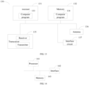
- FIG 12 is a schematic block diagram of a communication apparatus 120 provided in an embodiment of the present application.
- the communication apparatus 120 shown in FIG 12 can include a processing module 121 and a transceiver module 122.
- the transceiver module 122 can include a transmitting module and/or a receiving module, the transmitting module is used or realizing a transmitting function, the receiving module is used for realizing a receiving function, and the transceiver module 122 can realize the transmitting function and/or the receiving function.
- the communication apparatus 120 can be a terminal, or an apparatus in the terminal, or an apparatus which can be matched with the terminal.
- the communication apparatus 120 can be a network device, or an apparatus in the network device, or an apparatus which can be matched with the network device.
- the communication apparatus 120 is a network device, and includes:
- the processing module 121 is further configured for: for each first uplink data transmission layer, generating first DMRS port configuration tables respectively corresponding to different DMRS type parameters.
- the processing module 121 is further configured for, for each DMRS type parameter, generating a second DMRS port configuration table corresponding to the DMRS type parameter, in which the second DMRS port configuration table includes a first DMRS port configuration sub-table of each first uplink data transmission layer.
- the processing module 121 is further configured for: generating a sum third DMRS port configuration table, in which the third DMRS port configuration table includes contents in the form of one of the groups consisting of: a second DMRS port configuration sub-table of each first uplink data transmission layer corresponding to each DMRS type parameter; and a third DMRS port configuration sub-table of each DMRS type parameter for each first uplink data transmission layer.
- the transceiver module 122 is further configured for: determining a target DMRS type parameter and a target first uplink data transmission layer used by the terminal to perform the PUSCH transmission; determining, based on the target DMRS type parameter and the target first uplink data transmission layer, the one or more DMRS ports allocated for the PUSCH transmission; and indicating the one or more DMRS ports to the terminal.
- the transceiver module 122 is further configured for: in response to the DMRS port configuration table being a first DMRS port configuration table, determining one or more candidate first DMRS port configuration tables from the first DMRS port configuration tables based on the target DMRS type parameter and a first parameter in the target first uplink data transmission layer; determining a target first DMRS port configuration table from the one or more candidate first DMRS port configuration tables based on the target DMRS type parameter and a second parameter in the target first uplink data transmission layer; and determining, based on the target first DMRS port configuration table, the one or more DMRS ports allocated for the PUSCH transmission.
- the transceiver module 122 is further configured for: in response to the DMRS port configuration table being a second DMRS port configuration table, determining a candidate second DMRS port configuration table from second DMRS port configuration tables based on the target DMRS type parameter; determining a target first DMRS port configuration sub-table from the one or more candidate second DMRS port configuration tables based on the target first uplink data transmission layer; and determining, based on the target first DMRS port configuration sub-table, the one or more DMRS ports allocated for the PUSCH transmission.
- the transceiver module 122 is further configured for: in response to the DMRS port configuration table being a third DMRS port configuration table, determining a candidate second target DMRS port configuration sub-table from the third DMRS port configuration table based on the target DMRS type parameter; determining a target second DMRS port configuration sub-table from the candidate second DMRS port configuration sub-table based on the target first uplink data transmission layer, and determining one or more DMRS ports allocated for the PUSCH transmission based on the target second DMRS port configuration sub-table; or determining a candidate third target DMRS port configuration sub-table from the third DMRS port configuration table based on the target first uplink data transmission layer; determining a target third DMRS port configuration sub-table from the candidate third DMRS port configuration sub-table based on the target DMRS type parameter, and determining one or more DMRS ports allocated for the PUSCH transmission based on the target third DMRS port configuration sub-table.
- the transceiver module 122 is further configured for: indicating the one or more DMRS ports to the terminal via a DMRS port indication field in a downlink control information (DCI) signaling, in which the port indication field includes port index values of the one or more DMRS ports.
- DCI downlink control information
- a number of bits occupied by the port indication field is the same as a number of bits used for indicating one or more DMRS ports in a DMRS port configuration table corresponding to a second uplink data transmission layer.
- a number of bits of the DMRS port indication field is greater than a number of bits used for indicating the one DMRS port or a combination of ports in the DMRS port configuration table of the second uplink data transmission layer.
- the number of bits occupied by the port indication field is agreed by a protocol or configured by network or agreed by a protocol through the DMRS type parameter.
- the transceiver module 122 is further configured for: indicating the target DMRS type parameter and the target first uplink data transmission layer to the terminal.
- the transceiver module 122 is further configured for: indicating the target first uplink data transmission layer to the terminal explicitly or implicitly.
- the DMRS port configuration table includes a maximum number of symbols of a front-load DMRS corresponding to the DMRS type parameter and/or a DMRS mapping type.
- the communication apparatus 120 is a terminal, and includes:
- the processing module 121 is further configured for: for each layer of the first uplink data transmission layer, generating first DMRS port configuration tables respectively corresponding to different DMRS type parameters.
- the processing module 121 is further configured for, for each DMRS type parameter, generating a second DMRS port configuration table corresponding to the DMRS type parameter, in which the second DMRS port configuration table includes a first DMRS port configuration sub-table of each first uplink data transmission layer.
- the processing module 121 is further configured for: generating a sum third DMRS port configuration table, in which the third DMRS port configuration table includes contents in the form of one of the groups consisting of: a second DMRS port configuration sub-table of each first uplink data transmission layer corresponding to each DMRS type parameter; and a third DMRS port configuration sub-table of each DMRS type parameter for each first uplink data transmission layer.
- the transceiver module 122 is further configured for: determining a target DMRS type parameter and a target first uplink data transmission layer used by the terminal to perform the PUSCH transmission.
- the transceiver module 122 is further configured for: determining the target first uplink data transmission layer explicitly or implicitly.
- the transceiver module 122 is further configured for: receiving a downlink control information (DCI) signaling, and acquiring a DMRS port indication field from the DCI, in which the port indication field includes a port index value, and the port index value is used for indexing the one or more DMRS ports allocated for the PUSCH transmission; determining a DMRS port configuration table to be indexed from the DMRS port configuration table based on the target DMRS type parameter and the target first uplink data transmission layer; and determining the one or more DMRS ports from the DMRS port configuration table to be indexed based on the port index value.
- DCI downlink control information
- the transceiver module 122 is further configured for: in response to the DMRS port configuration table being a first DMRS port configuration table, determining one or more candidate first DMRS port configuration tables from the first DMRS port configuration tables based on the target DMRS type parameter and a first parameter in the target first uplink data transmission layer; and determining a target first DMRS port configuration table from the one or more candidate first DMRS port configuration tables based on the target DMRS type parameter and a second parameter in the target first uplink data transmission layer as the DMRS port configuration table to be indexed.
- the transceiver module 122 is further configured for: in response to the DMRS port configuration table being a second DMRS port configuration table, determining a candidate second DMRS port configuration table from second DMRS port configuration tables based on the target DMRS type parameter; and determining a target first DMRS port configuration sub-table from the candidate second DMRS port configuration table based on the target first uplink data transmission layer as the DMRS port configuration table to be indexed.
- the transceiver module 122 is further configured for: in response to the DMRS port configuration table being a third DMRS port configuration table, determining a candidate second target DMRS port configuration sub-table from the third DMRS port configuration table based on the target DMRS type parameter; determining a target second DMRS port configuration sub-table from the candidate second DMRS port configuration sub-table based on the target first uplink data transmission layer as the DMRS port configuration table to be indexed, and determining one or more DMRS ports allocated for the PUSCH transmission based on the target second DMRS port configuration sub-table; or determining a candidate third target DMRS port configuration sub-table from the third DMRS port configuration table based on the target first uplink data transmission layer; and determining a target third DMRS port configuration sub-table from the candidate third DMRS port configuration sub-table based on the target DMRS type parameter as the DMRS port configuration table to be indexed, and determining one or more DMRS ports allocated for the
- the transceiver module 122 is further configured for: directly performing indexing on the DMRS port configuration table to be indexed based on the port index value to determine the one or more DMRS ports; or determining a starting index value of a predefined table, determining an actual port index value according to the port index value and the starting index value, and performing indexing on the DMRS port configuration table to be indexed based on the actual port index value to determine the one or more DMRS ports.
- FIG 13 is a schematic structural diagram of another communication apparatus 130 provided in an embodiment of the present application.
- the communication apparatus 130 can be a terminal, or a network device, or a chip, a chip system or a processor, etc. supporting the network device to realize the above-mentioned method, or a chip, a ship system or a processor, etc. supporting the network device to realize the above-mentioned method.
- This apparatus can be used for realizing the method described in the above-mentioned method embodiment, and can specifically refer to the description for the above-mentioned method embodiment.
- the communication apparatus 130 can include one or more processors 131.
- the processor 131 can be a general-purpose processor or a special-purpose processor, etc.
- the processor can be a baseband processor or a central processor.
- the baseband processor can be used for processing a communication protocol and communication data
- the central processor can be used for controlling a communication apparatus (such as a base station, a baseband chip, a terminal, a terminal chip, and a DU or a CU), executing a computer program, and processing data of the computer program.
- the communication apparatus 130 can further include one or more memories 132 in which a computer program 134 can be stored, and the processor 131 executes the computer program 134, such that the communication apparatus 130 executes the method described in the above-mentioned method embodiment.
- the memory 132 can further store data.
- the communication apparatus 130 and the memory 132 can be disposed alone or integrated together.
- the communication apparatus 130 can further include a transceiver 135 and an antenna 136.
- the transceiver 135 can be referred to as a transceiver unit, a transceiver machine, or a transceiver circuit, etc., and is used for realizing a transceiver function.
- the transceiver 135 can include a receiver and a transmitter, the receiver can be referred to as a receiving machine or a receiving circuit, etc., and is used for realizing a receiving function; and the transmitter can be referred to as a transmitting machine or a transmitting circuit, etc., and is used for realizing a transmitting function.
- the communication apparatus 130 can further include one or more interface circuits 137.
- the interface circuit 137 is used for receiving code instructions and transmitting the code instructions to the processor 131.
- the processor 131 runs the code instructions, such that the communication apparatus 130 executes the method described in the above-mentioned method embodiment.
- the processor 131 can include a transceiver used for realizing receiving and transmitting functions.
- this transceiver can be a transceiver circuit, or an interface, or an interface circuit.
- the transceiver circuit, the interface or the interface circuit used for realizing the receiving and transmitting functions can be separated or integrated together.
- the above-mentioned transceiver circuit, interface or interface circuit can be used for reading and writing codes/data, or the above-mentioned transceiver circuit, interface or interface circuit can be used for transmitting or delivering signals.
- the processor 131 can store a computer program 133, and the computer program 133 runs on the processor 131, such that the communication apparatus 130 executes the method described in the above-mentioned method embodiment.
- the computer program 133 may be solidified in the processor 131, in this case, the processor 131 may be realized by hardware.
- the communication apparatus 130 can include a circuit which can realize the transmitting or receiving or communication function in the above-mentioned method embodiment.
- the processor and the transceiver that are described in the present application can be realized on an integrated circuit (IC), an analog IC, a radio frequency integrated circuit (RFIC), a mixed signal IC, an application specific integrated circuit (ASIC), a printed circuit board (PCB), an electronic device, etc.
- IC integrated circuit
- RFIC radio frequency integrated circuit
- ASIC application specific integrated circuit
- PCB printed circuit board
- This processor and the transceiver can also be made by using various IC process technologies, such as a complementary metal oxide semiconductor (CMOS), an nMetal-oxide-semiconductor (NMOS), a positive channel metal oxide semiconductor (PMOS), a bipolar junction transistor (BJT), a bipolar CMOS (BiCMOS), silicon germanium (SiGe), and gallium arsenide (GaAs).
- CMOS complementary metal oxide semiconductor
- NMOS nMetal-oxide-semiconductor
- PMOS positive channel metal oxide semiconductor
- BJT bipolar junction transistor
- BiCMOS bipolar CMOS
- SiGe silicon germanium
- GaAs gallium arsenide
- the communication apparatus described in above embodiment can be a transmitting device or a receiving device (such as the receiving device in the above-mentioned method embodiment), however, the scope of the communication apparatus described in the present application is not limited thereto, and it is possible that the structure of the communication apparatus is not limited by figure 13 .
- the communication apparatus can be an independent device or a part of a larger device.
- the communication apparatus can be:
- a situation that the communication apparatus can be a chip or a chip system can refer to the schematic structural diagram of a chip shown in FIG 14 .
- the chip shown in FIG 14 includes a processor 141 and an interface 142. There may be one or more processors 141, and there may be a plurality of interfaces 142.
- the chip further includes a memory 143, in which the memory 143 is used for storing a necessary computer program and data.
- Embodiments of the present application also provide a DMRS port indication system including a communication apparatus as a terminal such as a terminal in the aforementioned method embodiment and a communication apparatus as a network devices in the aforementioned embodiment of figure 12 , or the system includes a communication apparatus as a terminal such as the terminal in the aforementioned method embodiment and a communication apparatus as a network devices in the aforementioned embodiment of figure 13 .
- the present application further provides a computer-readable storage medium having instructions stored thereon, and the instructions, when executed by a computer, realize the function in any one of the above-mentioned method embodiments.
- the present application further provides a computer program product which, when executed by a computer, realizes the function in any one of the above-mentioned method embodiments.
- the above-mentioned embodiments can be entirely or partially realized through software, hardware, firmware or any combinations thereof.
- the embodiments can be entirely or partially realized in a form of a computer program product.
- the computer program product includes one or more computer programs. When the computer programs are loaded and executed on a computer, processes or functions based on the embodiments of the present application are entirely or partially generated.
- the computer can be a general-purpose computer, a special-purpose computer, a computer network, or other programmable apparatuses.
- the computer programs can be stored in a computer-readable storage medium, or transmitted from one computer-readable storage medium to another computer-readable storage medium, for example, the computer programs can be transmitted from one website, computer, server or data center to another website, computer, server or data center in a wired (such as a coaxial cable, an optical fiber, and a digital subscriber line (DSL)) or wireless (such as infrared, wireless, and microwave) manner.
- the computer-readable storage medium can be any available medium that can be accessed by the computer or an integrated data storage device such as a server and a data center including one or more available media.
- the available medium can be a magnetic medium (such as floppy disk, a hard disk, and a cassette), an optical medium (such as a high-density digital video disc (DVD)), or a semiconductor medium (such as a solid-state disk (SSD)), etc.
- a magnetic medium such as floppy disk, a hard disk, and a cassette
- an optical medium such as a high-density digital video disc (DVD)
- DVD high-density digital video disc
- SSD solid-state disk
- At least one in the present application can be described as one or more, a plurality of can be two, three, four or more, which is not limited in the present application.
- technical features in such a technical feature are distinguished by “first”, “second”, “third”, “A”, “B”, “C”, “D”, etc., and there are no chronological or size order among the technical features described by the "first”, “second”, “third”, “A”, “B”, “C”, and “D”.
- a corresponding relationship shown in each table in the present application can be configured or predefined.
- a value of information in each table is only illustrative, and other values can be configured, which is not limited in the present application.
- corresponding relationships shown in certain lines are not configured.
- appropriate deformation adjustment such as splitting and merging, can be made based on the above-mentioned tables.
- Names of parameters shown in titles in each of the above-mentioned tables can also adopt other names that can be understood by the communication apparatus, and the values or expressions of the parameters thereof can also adopt other values or expressions that can be understood by the communication apparatus.
- each of the above-mentioned tables can also adopt other data structures, such as arrays, queues, containers, stacks, linear tables, pointers, linked lists, trees, graphs, structures, classes, heaps, and hash tables or Hash tables.
- Pre-definition in the present application can be understood as definition, preliminary definition, storage, pre-storage, pre-negotiation, pre-configuration, solidification, or pre-burning.
Landscapes
- Engineering & Computer Science (AREA)
- Signal Processing (AREA)
- Computer Networks & Wireless Communication (AREA)
- Mobile Radio Communication Systems (AREA)
Applications Claiming Priority (1)
| Application Number | Priority Date | Filing Date | Title |
|---|---|---|---|
| PCT/CN2022/082868 WO2023178622A1 (fr) | 2022-03-24 | 2022-03-24 | Procédé d'indication de port dmrs et appareil associé |
Publications (2)
| Publication Number | Publication Date |
|---|---|
| EP4503793A1 true EP4503793A1 (fr) | 2025-02-05 |
| EP4503793A4 EP4503793A4 (fr) | 2025-12-31 |
Family
ID=88099512
Family Applications (1)
| Application Number | Title | Priority Date | Filing Date |
|---|---|---|---|
| EP22932687.1A Pending EP4503793A4 (fr) | 2022-03-24 | 2022-03-24 | Procédé d'indication de port dmrs et appareil associé |
Country Status (4)
| Country | Link |
|---|---|
| US (1) | US20250219784A1 (fr) |
| EP (1) | EP4503793A4 (fr) |
| CN (1) | CN117158086A (fr) |
| WO (1) | WO2023178622A1 (fr) |
Family Cites Families (5)
| Publication number | Priority date | Publication date | Assignee | Title |
|---|---|---|---|---|
| CN108631998B (zh) * | 2017-03-24 | 2020-07-28 | 华为技术有限公司 | 一种参考信号映射方法及网络设备、终端设备 |
| CN109151970B (zh) * | 2017-06-16 | 2023-10-20 | 华为技术有限公司 | 一种发送功率的确定方法、处理芯片及通信设备 |
| WO2019090774A1 (fr) * | 2017-11-13 | 2019-05-16 | Nec Corporation | Procédés et appareils de configuration de signal de référence de démodulation |
| CN114826525B (zh) * | 2019-01-11 | 2025-05-27 | 华为技术有限公司 | 发送和接收指示的方法和装置 |
| WO2020222605A1 (fr) * | 2019-05-02 | 2020-11-05 | 엘지전자 주식회사 | Procédé d'émission et de réception de canal de données dans un système de communication sans fil, et appareil associé |
-
2022
- 2022-03-24 EP EP22932687.1A patent/EP4503793A4/fr active Pending
- 2022-03-24 US US18/850,508 patent/US20250219784A1/en active Pending
- 2022-03-24 CN CN202280000685.2A patent/CN117158086A/zh active Pending
- 2022-03-24 WO PCT/CN2022/082868 patent/WO2023178622A1/fr not_active Ceased
Also Published As
| Publication number | Publication date |
|---|---|
| US20250219784A1 (en) | 2025-07-03 |
| EP4503793A4 (fr) | 2025-12-31 |
| CN117158086A (zh) | 2023-12-01 |
| WO2023178622A1 (fr) | 2023-09-28 |
Similar Documents
| Publication | Publication Date | Title |
|---|---|---|
| EP4518201A1 (fr) | Procédé et dispositif de détermination d'état d'indication de configuration | |
| US20240340989A1 (en) | Transmission configuration indicator (tci) state configuration method and apparatus | |
| JP2025514252A (ja) | 伝送設定指示状態を決定する方法及び装置 | |
| WO2024239156A1 (fr) | Procédés et appareils de communication, et support de stockage | |
| EP4492703A1 (fr) | Procédé de rapport de capacité de commutation d'antenne et appareil faisant appel à celui-ci | |
| WO2023004653A1 (fr) | Procédé de configuration de structure de créneau et appareil associé | |
| US20250240776A1 (en) | Method and apparatus for configuring frequency domain resources | |
| WO2024031577A1 (fr) | Procédé et appareil d'attribution de ressources de domaine temporel, dispositif et support d'enregistr§ement | |
| WO2024164278A1 (fr) | Procédés et appareil de communication en liaison montante basés sur une transmission simultanée à panneaux multiples | |
| CN116724529A (zh) | 上行相位跟踪参考信号ptrs的传输方法及通信装置 | |
| WO2023212881A1 (fr) | Procédé de transmission de signal de référence de démodulation (dmrs), et appareil | |
| EP4503793A1 (fr) | Procédé d'indication de port dmrs et appareil associé | |
| US20250219786A1 (en) | Method and apparatus for sending/receiving information for non-codebook based pusch | |
| US20240284417A1 (en) | Time domain resource assignment method and apparatus | |
| WO2024065103A1 (fr) | Procédé de commande de puissance de liaison montante et appareil associé | |
| CN115997448A (zh) | 频域资源的确定方法及装置 | |
| EP4507421A1 (fr) | Procédé et appareil de configuration de ressources dans le domaine fréquentiel | |
| EP4668972A1 (fr) | Procédé et appareil de traitement d'un canal de commande de liaison descendante physique (pdcch) | |
| US20250330819A1 (en) | Method and device for determining size of buffer of data link layer l2 | |
| EP4564751A1 (fr) | Procédé et appareil d'estimation de canal | |
| US20250386339A1 (en) | Indication method and apparatus | |
| WO2024031578A1 (fr) | Procédé d'envoi de canal, procédé de réception de canal, appareil, dispositif et support de stockage | |
| WO2024087221A1 (fr) | Procédé et appareil d'indication basés sur un état d'indication de configuration de transmission (tci) | |
| US20240188052A1 (en) | Method and device for determining time domain resources | |
| WO2023231036A1 (fr) | Procédé de traitement de bloc de transmission et appareil associé |
Legal Events
| Date | Code | Title | Description |
|---|---|---|---|
| STAA | Information on the status of an ep patent application or granted ep patent |
Free format text: STATUS: THE INTERNATIONAL PUBLICATION HAS BEEN MADE |
|
| PUAI | Public reference made under article 153(3) epc to a published international application that has entered the european phase |
Free format text: ORIGINAL CODE: 0009012 |
|
| STAA | Information on the status of an ep patent application or granted ep patent |
Free format text: STATUS: REQUEST FOR EXAMINATION WAS MADE |
|
| 17P | Request for examination filed |
Effective date: 20241018 |
|
| AK | Designated contracting states |
Kind code of ref document: A1 Designated state(s): AL AT BE BG CH CY CZ DE DK EE ES FI FR GB GR HR HU IE IS IT LI LT LU LV MC MK MT NL NO PL PT RO RS SE SI SK SM TR |
|
| DAV | Request for validation of the european patent (deleted) | ||
| DAX | Request for extension of the european patent (deleted) | ||
| A4 | Supplementary search report drawn up and despatched |
Effective date: 20251203 |
|
| RIC1 | Information provided on ipc code assigned before grant |
Ipc: H04W 72/04 20230101AFI20251127BHEP Ipc: H04W 56/00 20090101ALI20251127BHEP Ipc: H04W 72/12 20230101ALI20251127BHEP Ipc: H04L 5/00 20060101ALI20251127BHEP |