EP4503864A1 - Röntgenstrahlerzeugungsvorrichtung und röntgenbildgebungsvorrichtung - Google Patents
Röntgenstrahlerzeugungsvorrichtung und röntgenbildgebungsvorrichtung Download PDFInfo
- Publication number
- EP4503864A1 EP4503864A1 EP22933894.2A EP22933894A EP4503864A1 EP 4503864 A1 EP4503864 A1 EP 4503864A1 EP 22933894 A EP22933894 A EP 22933894A EP 4503864 A1 EP4503864 A1 EP 4503864A1
- Authority
- EP
- European Patent Office
- Prior art keywords
- space
- ray generating
- insulating member
- generating apparatus
- insulating
- Prior art date
- Legal status (The legal status is an assumption and is not a legal conclusion. Google has not performed a legal analysis and makes no representation as to the accuracy of the status listed.)
- Pending
Links
Images



Classifications
-
- H—ELECTRICITY
- H01—ELECTRIC ELEMENTS
- H01J—ELECTRIC DISCHARGE TUBES OR DISCHARGE LAMPS
- H01J35/00—X-ray tubes
- H01J35/02—Details
- H01J35/16—Vessels; Containers; Shields associated therewith
-
- H—ELECTRICITY
- H05—ELECTRIC TECHNIQUES NOT OTHERWISE PROVIDED FOR
- H05G—X-RAY TECHNIQUE
- H05G1/00—X-ray apparatus involving X-ray tubes; Circuits therefor
- H05G1/02—Constructional details
- H05G1/025—Means for cooling the X-ray tube or the generator
-
- H—ELECTRICITY
- H05—ELECTRIC TECHNIQUES NOT OTHERWISE PROVIDED FOR
- H05G—X-RAY TECHNIQUE
- H05G1/00—X-ray apparatus involving X-ray tubes; Circuits therefor
- H05G1/02—Constructional details
- H05G1/04—Mounting the X-ray tube within a closed housing
-
- H—ELECTRICITY
- H05—ELECTRIC TECHNIQUES NOT OTHERWISE PROVIDED FOR
- H05G—X-RAY TECHNIQUE
- H05G1/00—X-ray apparatus involving X-ray tubes; Circuits therefor
- H05G1/02—Constructional details
- H05G1/04—Mounting the X-ray tube within a closed housing
- H05G1/06—X-ray tube and at least part of the power supply apparatus being mounted within the same housing
-
- H—ELECTRICITY
- H01—ELECTRIC ELEMENTS
- H01J—ELECTRIC DISCHARGE TUBES OR DISCHARGE LAMPS
- H01J2235/00—X-ray tubes
- H01J2235/12—Cooling
- H01J2235/1216—Cooling of the vessel
-
- H—ELECTRICITY
- H01—ELECTRIC ELEMENTS
- H01J—ELECTRIC DISCHARGE TUBES OR DISCHARGE LAMPS
- H01J2235/00—X-ray tubes
- H01J2235/12—Cooling
- H01J2235/1225—Cooling characterised by method
- H01J2235/1262—Circulating fluids
-
- H—ELECTRICITY
- H01—ELECTRIC ELEMENTS
- H01J—ELECTRIC DISCHARGE TUBES OR DISCHARGE LAMPS
- H01J2235/00—X-ray tubes
- H01J2235/16—Vessels
- H01J2235/165—Shielding arrangements
- H01J2235/167—Shielding arrangements against thermal (heat) energy
-
- H—ELECTRICITY
- H05—ELECTRIC TECHNIQUES NOT OTHERWISE PROVIDED FOR
- H05G—X-RAY TECHNIQUE
- H05G1/00—X-ray apparatus involving X-ray tubes; Circuits therefor
- H05G1/08—Electrical details
- H05G1/26—Measuring, controlling or protecting
Definitions
- the present invention relates to an X-ray generating apparatus and an X-ray imaging apparatus.
- PTL 1 discloses an X-ray generating apparatus including an X-ray generating unit, a voltage supply unit, a storage housing that stores the X-ray generating unit and the voltage supply unit, and insulating components arranged between the internal surface of the storage housing and at least part of the X-ray generating unit.
- the insulating components can constitute an insulating housing surrounding the X-ray generating unit and the voltage supply unit.
- the insulating housing can include a first housing having a first opening and a second housing having a second opening. The second housing can be arranged so as to accommodate part of the first housing in the second opening and cover the first opening of the first housing.
- the heat generated from the voltage supply unit and the X-ray generating unit can increase the temperature in the insulating housing.
- the insulating housing can function as at least a heat-insulating housing and prevent heat from radiating from the X-ray generating apparatus.
- the present invention provides a technique advantageous in suppressing an increase in the temperature of the X-ray generating apparatus by promoting the radiation of heat from the X-ray generating apparatus.
- a first aspect of the present invention is related to an X-ray generating apparatus, and the X-ray generating apparatus comprises: an X-ray generating unit having a first bottom surface including a radiation portion configured to emit X-rays, a second bottom surface on an opposite side to the first bottom surface, and a side surface; a driving circuit configured to drive the X-ray generating unit; an accommodation housing configured to accommodate the X-ray generating unit and the driving circuit; and an insulating component arranged in the accommodation housing, wherein the insulating component includes a first insulating member arranged between the driving circuit and the accommodation housing and a second insulating member arranged between the X-ray generating unit and the accommodation housing, at least part of a first space is defined by an external surface of the first insulating member and an internal surface of the accommodation housing, at least part of a second space is defined by an external surface of the second insulating member and the internal surface of the accommodation housing, at least part of a third space is defined by the side surface of the X
- a second aspect of the present invention comprises the X-ray generating apparatus according to the first aspect; and an X-ray detector configured to detect X-rays emitted from the X-ray generating apparatus.
- Fig. 1 is a schematic sectional view of the arrangement of an X-ray generating apparatus 100 according to one embodiment.
- the X-ray generating apparatus 100 includes an X-ray generating unit 12, a driving circuit 14 that drives the X-ray generating unit 12, an accommodation housing 20 that accommodates the X-ray generating unit 12 and the driving circuit 14, and an insulating component 50 arranged in the accommodation housing 20.
- the X-ray generating unit 12 can have a first bottom surface 126 including a radiation portion 122 that radiates X-rays, a second bottom surface 127 on the opposite side to the first bottom surface 126, and a side surface 128.
- the X-ray generating unit 12 can have, for example, a cylindrical shape.
- the X-ray generating unit 12 can include an insulating tube 124, an anode 123 including the radiation portion 122, and a cathode 125 including an electron emitting unit 121 that emits electrons.
- the anode 123 can be arranged on one end of the insulating tube 124 so as to form the first bottom surface 126.
- the cathode 125 can be arranged on the other end of the insulating tube 124 so as to form the second bottom surface 127.
- the radiation portion 122 can include a target that generates X-rays upon receiving electrons emitted from the electron emitting unit 121 in the positive direction of the Z-axis and a target holding portion that holds the target.
- the driving circuit 14 can generate one or a plurality of negative drive potentials for driving the X-ray generating unit 12 upon receiving an externally supplied voltage.
- the X-ray generating unit 12 is configured as, for example, an X-ray generating unit based on an anode ground scheme, and the anode 123 of the X-ray generating unit 12 can be electrically connected to the accommodation housing 20.
- the negative potential generated by the driving circuit 14 can be supplied to the cathode 125 of the X-ray generating unit 12 via a cable 16.
- the driving circuit 14 can generate, for example, a potential difference of 100 kV (for example, -100 kV).
- the cable 16 can include a conductive member and an insulating material covering the conductive member but may not include the insulating material.
- the X-ray generating unit 12 and the driving circuit 14 are heat sources.
- the space between the accommodation housing 20 and the insulating component 50 and the space inside the insulating component 50 can be filled with an insulating liquid (for example, an insulating oil).
- the cathode 125 of the X-ray generating unit 12 is electrically insulated to the accommodation housing 20.
- the accommodation housing 20 can be shaped such that a portion on which the X-ray generating unit 12 is arranged protrudes from the peripheral portion of the portion.
- the accommodation housing 20 can be shaped such that a central portion including the portion on which the X-ray generating unit 12 is arranged protrudes from the peripheral portion.
- Such a structure is advantageous in arranging the X-ray generating unit 12 near a sample.
- the accommodation housing 20 can include a portion facing a bottom surface 141 of the driving circuit 14 through the insulating component 50 and a portion facing a side surface 142 of the driving circuit 14 through the insulating component 50.
- the bottom surface 141 may be formed of one flat surface, a plurality of flat surfaces, or surfaces including a curved surface.
- the side surface 142 may be formed of one curved surface such as a cylindrical surface, a plurality of flat surfaces, or surfaces including a curved surface.
- the accommodation housing 20 can include a second accommodation portion 22 surrounding all or part of the X-ray generating unit 12 (around the Z-axis).
- the accommodation housing 20 can include a portion facing the side surface 128 of the X-ray generating unit 12 through the insulating component 50.
- the second accommodation portion 22 is arranged so as to define a space protruding from a space defined by the first accommodation portion 21 in the positive direction of the Z-axis.
- the insulating component 50 can be formed of a resin impregnated glass cloth laminated body (for example, a laminated plate or a laminated tube) formed by heating and pressurizing.
- the insulating component 50 can include a first insulating member 51 arranged between the driving circuit 14 and the accommodation housing 20 (or the first accommodation portion 21) and a second insulating member 52 arranged between the X-ray generating unit 12 and the accommodation housing 20 (or the second accommodation portion 22).
- the insulating component 50 can include the first insulating member 51 surrounding all or part of the driving circuit 14 (around the Z-axis).
- the first insulating member 51 may surround all or part of the driving circuit 14 and part of the X-ray generating unit 12 (around the Z-axis).
- the first insulating member 51 can include a portion facing the bottom surface 141 of the driving circuit 14 and a portion facing the side surface 142 of the driving circuit 14.
- the insulating component 50 can include the second insulating member 52 surrounding all or part of the X-ray generating unit 12 (around the Z-axis).
- the second insulating member 52 can include a portion facing the side surface 128 of the X-ray generating unit 12.
- the second insulating member 52 is arranged so as to define a space protruding from the space defined by the first insulating member 51 in the positive direction of the Z-axis.
- the first insulating member 51 can include a first portion 511 extending from the second insulating member 52 in the radiation direction, a second portion 512 expanding parallel to the first portion 511, and a third portion 513 extending in the Z-axis direction so as to connect the first portion 511 and the second portion 512.
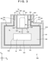
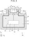
- At least part of a first space S1 can be defined by the external surface of the first insulating member 51 and the internal surface of the accommodation housing 20.
- At least part of a second space S2 can be defined by the external surface of the second insulating member 52 and the internal surface of the accommodation housing 20.
- At least part of a third space S3 can be defined by the side surface 128 of the X-ray generating unit 12 and the internal surface of the second insulating member 52.
- At least part of a fourth space S4 can be defined by the second bottom surface 127 of the X-ray generating unit 12 and the internal surface of the first insulating member 51.
- the first space S1, the second space S2, the third space S3, and the fourth space S4 can be filled with an insulating liquid IL.
- the insulating component 50 can be arranged so as to form a plurality of communicating portions that cause the internal spaces of the insulating component 50 (the third space S3 and the fourth space S4) to communicate with the external spaces of the insulating component 50 (the first space S1 and the second space S2).
- the second space S2 can communicate with the third space S3 through a first communicating portion C1 without intervention of the first space S1 and the fourth space S4.
- the first space S1 can communicate with the fourth space S4 through a second communicating portion C2 without intervention of the second space S2 and the third space S3.
- the insulating component 50 can be configured to cause the second space S2 to communicate with the third space S3 through the first communicating portion C1 without intervention of the first space S1 and the fourth space S4.
- the insulating component 50 can be configured to cause the first space S1 to communicate with the fourth space S4 through the second communicating portion C2 without intervention of the second space S2 and the third space S3.
- the first communicating portion C1 makes it possible to move the insulating liquid IL from the third space S3 to the second space S2 and to move the insulating liquid IL from the second space S2 to the third space S3.
- the second communicating portion C2 makes it possible to move the insulating liquid IL from the first space S1 to the fourth space S4 and to move the insulating liquid IL from the fourth space S4 to the first space S1.
- the insulating liquid IL can convect or circulate so as to reach the second space S2 from the third space S3 through the first communicating portion C1, reach the first space S1 from the second space S2, reach the fourth space S4 from the first space S1 through the second communicating portion C2, and reach the third space S3 from the fourth space S4.
- the insulating liquid IL tends to stay in the internal spaces of the second accommodation portion 22, that is, the second space S2 and the third space S3.
- the staying of the insulating liquid IL can accumulate heat and electric charge generated by the X-ray generating unit 12 and the driving circuit 14.
Landscapes
- Health & Medical Sciences (AREA)
- General Health & Medical Sciences (AREA)
- Toxicology (AREA)
- X-Ray Techniques (AREA)
Applications Claiming Priority (1)
| Application Number | Priority Date | Filing Date | Title |
|---|---|---|---|
| PCT/JP2022/016707 WO2023188335A1 (ja) | 2022-03-31 | 2022-03-31 | X線発生装置およびx線撮像装置 |
Publications (2)
| Publication Number | Publication Date |
|---|---|
| EP4503864A1 true EP4503864A1 (de) | 2025-02-05 |
| EP4503864A4 EP4503864A4 (de) | 2025-05-28 |
Family
ID=88200359
Family Applications (1)
| Application Number | Title | Priority Date | Filing Date |
|---|---|---|---|
| EP22933894.2A Pending EP4503864A4 (de) | 2022-03-31 | 2022-03-31 | Röntgenstrahlerzeugungsvorrichtung und röntgenbildgebungsvorrichtung |
Country Status (6)
| Country | Link |
|---|---|
| US (1) | US12193134B2 (de) |
| EP (1) | EP4503864A4 (de) |
| JP (1) | JP7430296B1 (de) |
| CN (1) | CN118975407A (de) |
| TW (1) | TWI863190B (de) |
| WO (1) | WO2023188335A1 (de) |
Family Cites Families (12)
| Publication number | Priority date | Publication date | Assignee | Title |
|---|---|---|---|---|
| DE4207174A1 (de) | 1992-03-06 | 1993-09-16 | Siemens Ag | Roentgenstrahler mit einer befestigungsvorrichtung |
| US6765987B2 (en) * | 2001-03-15 | 2004-07-20 | Safe Food Technologies, Inc. | Resonant plasma x-ray source |
| JP4880771B2 (ja) * | 2010-07-21 | 2012-02-22 | 株式会社ジョブ | X線発生装置 |
| WO2013042812A1 (ko) * | 2011-09-23 | 2013-03-28 | 주식회사 엑스엘 | 일체형 엑스선 발생장치 |
| WO2015145668A1 (ja) * | 2014-03-27 | 2015-10-01 | 株式会社ニコン | X線発生装置、x線装置および構造物の製造方法 |
| JP2016100290A (ja) * | 2014-11-26 | 2016-05-30 | キヤノン株式会社 | X線発生装置及びそれを用いたx線撮影システム |
| JP6525941B2 (ja) * | 2016-10-28 | 2019-06-05 | キヤノン株式会社 | X線発生装置及び、x線撮影システム |
| JP6543377B1 (ja) * | 2018-04-12 | 2019-07-10 | 浜松ホトニクス株式会社 | X線発生装置 |
| KR102362008B1 (ko) * | 2019-04-15 | 2022-02-14 | 캐논 아네르바 가부시키가이샤 | X선 발생 장치 및 x선 촬영 장치 |
| JP6683903B1 (ja) * | 2019-09-03 | 2020-04-22 | キヤノンアネルバ株式会社 | X線発生装置およびx線撮像装置 |
| WO2021044525A1 (ja) * | 2019-09-03 | 2021-03-11 | キヤノンアネルバ株式会社 | X線発生装置およびx線撮影装置 |
| WO2024189662A1 (ja) * | 2023-03-10 | 2024-09-19 | キヤノンアネルバ株式会社 | X線発生装置、x線撮像装置およびモールド変圧器 |
-
2022
- 2022-03-31 EP EP22933894.2A patent/EP4503864A4/de active Pending
- 2022-03-31 CN CN202280094484.3A patent/CN118975407A/zh active Pending
- 2022-03-31 JP JP2023565995A patent/JP7430296B1/ja active Active
- 2022-03-31 WO PCT/JP2022/016707 patent/WO2023188335A1/ja not_active Ceased
-
2023
- 2023-03-24 TW TW112111125A patent/TWI863190B/zh active
-
2024
- 2024-07-24 US US18/782,498 patent/US12193134B2/en active Active
Also Published As
| Publication number | Publication date |
|---|---|
| US20240381514A1 (en) | 2024-11-14 |
| US12193134B2 (en) | 2025-01-07 |
| KR20240167049A (ko) | 2024-11-26 |
| CN118975407A (zh) | 2024-11-15 |
| TW202408317A (zh) | 2024-02-16 |
| JP7430296B1 (ja) | 2024-02-09 |
| TWI863190B (zh) | 2024-11-21 |
| JPWO2023188335A1 (de) | 2023-10-05 |
| WO2023188335A1 (ja) | 2023-10-05 |
| EP4503864A4 (de) | 2025-05-28 |
Similar Documents
| Publication | Publication Date | Title |
|---|---|---|
| US9070531B2 (en) | X-ray generator tube having improved cooling container and X-ray imaging apparatus including the same | |
| TWI749520B (zh) | X射線產生裝置及x射線攝影裝置 | |
| US11043351B2 (en) | X-ray source and method for manufacturing an X-ray source | |
| CN114303222B (zh) | X射线产生装置及x射线拍摄装置 | |
| US10969347B2 (en) | X-ray generation apparatus and X-ray imaging apparatus | |
| US20240306283A1 (en) | X-ray generating apparatus, x-ray imaging apparatus, and mold transformer | |
| US11166360B2 (en) | X-ray generator | |
| KR102252811B1 (ko) | X선 발생 장치 및 x선 촬영 시스템 | |
| CN113272931A (zh) | X射线产生管、x射线产生装置及x射线成像装置 | |
| EP4503864A1 (de) | Röntgenstrahlerzeugungsvorrichtung und röntgenbildgebungsvorrichtung | |
| KR20190093335A (ko) | 휴대용 엑스선 발생장치 | |
| KR102960796B1 (ko) | X선 발생 장치 및 x선 촬상 장치 | |
| GB2587103A (en) | X-ray generator | |
| US20130156160A1 (en) | Compact radiation generator | |
| CN218391127U (zh) | 双能射线源装置及断层摄影机 | |
| JP2008226783A (ja) | X線発生器及びx線装置 | |
| US12230413B2 (en) | Electron beam generator, electron beam emission device and X-ray emission device | |
| CN117255468A (zh) | 分布式x射线源以及具有该射线源的ct设备 | |
| EP4395470A1 (de) | Elektrische komponente, röntgenerzeugungsvorrichtung und röntgenbildgebungsvorrichtung | |
| US12176175B2 (en) | Electron beam generation source, electron beam emission device, and x-ray emission device | |
| EP3897077A1 (de) | Röntgenvorrichtung | |
| KR20180032801A (ko) | 엑스선 튜브 및 이를 포함하는 엑스선 발생 장치 | |
| JP5449118B2 (ja) | 透過型放射線管、放射線発生装置および放射線撮影装置 | |
| JP2006024480A (ja) | X線管、x線発生器、x線検査装置 | |
| JP2015056247A (ja) | 放射線発生装置、およびそれを用いた放射線撮影装置 |
Legal Events
| Date | Code | Title | Description |
|---|---|---|---|
| STAA | Information on the status of an ep patent application or granted ep patent |
Free format text: STATUS: UNKNOWN |
|
| STAA | Information on the status of an ep patent application or granted ep patent |
Free format text: STATUS: THE INTERNATIONAL PUBLICATION HAS BEEN MADE |
|
| PUAI | Public reference made under article 153(3) epc to a published international application that has entered the european phase |
Free format text: ORIGINAL CODE: 0009012 |
|
| STAA | Information on the status of an ep patent application or granted ep patent |
Free format text: STATUS: REQUEST FOR EXAMINATION WAS MADE |
|
| 17P | Request for examination filed |
Effective date: 20241022 |
|
| AK | Designated contracting states |
Kind code of ref document: A1 Designated state(s): AL AT BE BG CH CY CZ DE DK EE ES FI FR GB GR HR HU IE IS IT LI LT LU LV MC MK MT NL NO PL PT RO RS SE SI SK SM TR |
|
| A4 | Supplementary search report drawn up and despatched |
Effective date: 20250428 |
|
| RIC1 | Information provided on ipc code assigned before grant |
Ipc: H05G 1/26 20060101ALI20250422BHEP Ipc: H05G 1/04 20060101ALI20250422BHEP Ipc: H05G 1/02 20060101ALI20250422BHEP Ipc: H01J 35/16 20060101ALI20250422BHEP Ipc: H05G 1/06 20060101AFI20250422BHEP |
|
| DAV | Request for validation of the european patent (deleted) | ||
| DAX | Request for extension of the european patent (deleted) |