EP4505981A1 - Poignée pivotante latérale universelle - Google Patents
Poignée pivotante latérale universelle Download PDFInfo
- Publication number
- EP4505981A1 EP4505981A1 EP24193328.2A EP24193328A EP4505981A1 EP 4505981 A1 EP4505981 A1 EP 4505981A1 EP 24193328 A EP24193328 A EP 24193328A EP 4505981 A1 EP4505981 A1 EP 4505981A1
- Authority
- EP
- European Patent Office
- Prior art keywords
- handle
- body portion
- surgical instrument
- positioning tip
- slots
- Prior art date
- Legal status (The legal status is an assumption and is not a legal conclusion. Google has not performed a legal analysis and makes no representation as to the accuracy of the status listed.)
- Pending
Links
Images


Classifications
-
- A—HUMAN NECESSITIES
- A61—MEDICAL OR VETERINARY SCIENCE; HYGIENE
- A61F—FILTERS IMPLANTABLE INTO BLOOD VESSELS; PROSTHESES; DEVICES PROVIDING PATENCY TO, OR PREVENTING COLLAPSING OF, TUBULAR STRUCTURES OF THE BODY, e.g. STENTS; ORTHOPAEDIC, NURSING OR CONTRACEPTIVE DEVICES; FOMENTATION; TREATMENT OR PROTECTION OF EYES OR EARS; BANDAGES, DRESSINGS OR ABSORBENT PADS; FIRST-AID KITS
- A61F2/00—Filters implantable into blood vessels; Prostheses, i.e. artificial substitutes or replacements for parts of the body; Appliances for connecting them with the body; Devices providing patency to, or preventing collapsing of, tubular structures of the body, e.g. stents
- A61F2/02—Prostheses implantable into the body
- A61F2/30—Joints
- A61F2/46—Special tools for implanting artificial joints
- A61F2/4603—Special tools for implanting artificial joints for insertion or extraction of endoprosthetic joints or of accessories thereof
- A61F2/4611—Special tools for implanting artificial joints for insertion or extraction of endoprosthetic joints or of accessories thereof of spinal prostheses
-
- A—HUMAN NECESSITIES
- A61—MEDICAL OR VETERINARY SCIENCE; HYGIENE
- A61F—FILTERS IMPLANTABLE INTO BLOOD VESSELS; PROSTHESES; DEVICES PROVIDING PATENCY TO, OR PREVENTING COLLAPSING OF, TUBULAR STRUCTURES OF THE BODY, e.g. STENTS; ORTHOPAEDIC, NURSING OR CONTRACEPTIVE DEVICES; FOMENTATION; TREATMENT OR PROTECTION OF EYES OR EARS; BANDAGES, DRESSINGS OR ABSORBENT PADS; FIRST-AID KITS
- A61F2/00—Filters implantable into blood vessels; Prostheses, i.e. artificial substitutes or replacements for parts of the body; Appliances for connecting them with the body; Devices providing patency to, or preventing collapsing of, tubular structures of the body, e.g. stents
- A61F2/02—Prostheses implantable into the body
- A61F2/30—Joints
- A61F2/44—Joints for the spine, e.g. vertebrae, spinal discs
- A61F2/4455—Joints for the spine, e.g. vertebrae, spinal discs for the fusion of spinal bodies, e.g. intervertebral fusion of adjacent spinal bodies, e.g. fusion cages
- A61F2/4465—Joints for the spine, e.g. vertebrae, spinal discs for the fusion of spinal bodies, e.g. intervertebral fusion of adjacent spinal bodies, e.g. fusion cages having a circular or kidney shaped cross-section substantially perpendicular to the axis of the spine
-
- A—HUMAN NECESSITIES
- A61—MEDICAL OR VETERINARY SCIENCE; HYGIENE
- A61F—FILTERS IMPLANTABLE INTO BLOOD VESSELS; PROSTHESES; DEVICES PROVIDING PATENCY TO, OR PREVENTING COLLAPSING OF, TUBULAR STRUCTURES OF THE BODY, e.g. STENTS; ORTHOPAEDIC, NURSING OR CONTRACEPTIVE DEVICES; FOMENTATION; TREATMENT OR PROTECTION OF EYES OR EARS; BANDAGES, DRESSINGS OR ABSORBENT PADS; FIRST-AID KITS
- A61F2/00—Filters implantable into blood vessels; Prostheses, i.e. artificial substitutes or replacements for parts of the body; Appliances for connecting them with the body; Devices providing patency to, or preventing collapsing of, tubular structures of the body, e.g. stents
- A61F2/02—Prostheses implantable into the body
- A61F2/30—Joints
- A61F2/44—Joints for the spine, e.g. vertebrae, spinal discs
- A61F2/4455—Joints for the spine, e.g. vertebrae, spinal discs for the fusion of spinal bodies, e.g. intervertebral fusion of adjacent spinal bodies, e.g. fusion cages
- A61F2/447—Joints for the spine, e.g. vertebrae, spinal discs for the fusion of spinal bodies, e.g. intervertebral fusion of adjacent spinal bodies, e.g. fusion cages substantially parallelepipedal, e.g. having a rectangular or trapezoidal cross-section
-
- A—HUMAN NECESSITIES
- A61—MEDICAL OR VETERINARY SCIENCE; HYGIENE
- A61F—FILTERS IMPLANTABLE INTO BLOOD VESSELS; PROSTHESES; DEVICES PROVIDING PATENCY TO, OR PREVENTING COLLAPSING OF, TUBULAR STRUCTURES OF THE BODY, e.g. STENTS; ORTHOPAEDIC, NURSING OR CONTRACEPTIVE DEVICES; FOMENTATION; TREATMENT OR PROTECTION OF EYES OR EARS; BANDAGES, DRESSINGS OR ABSORBENT PADS; FIRST-AID KITS
- A61F2/00—Filters implantable into blood vessels; Prostheses, i.e. artificial substitutes or replacements for parts of the body; Appliances for connecting them with the body; Devices providing patency to, or preventing collapsing of, tubular structures of the body, e.g. stents
- A61F2/02—Prostheses implantable into the body
- A61F2/30—Joints
- A61F2002/30001—Additional features of subject-matter classified in A61F2/28, A61F2/30 and subgroups thereof
- A61F2002/30316—The prosthesis having different structural features at different locations within the same prosthesis; Connections between prosthetic parts; Special structural features of bone or joint prostheses not otherwise provided for
- A61F2002/30535—Special structural features of bone or joint prostheses not otherwise provided for
- A61F2002/30537—Special structural features of bone or joint prostheses not otherwise provided for adjustable
- A61F2002/30538—Special structural features of bone or joint prostheses not otherwise provided for adjustable for adjusting angular orientation
-
- A—HUMAN NECESSITIES
- A61—MEDICAL OR VETERINARY SCIENCE; HYGIENE
- A61F—FILTERS IMPLANTABLE INTO BLOOD VESSELS; PROSTHESES; DEVICES PROVIDING PATENCY TO, OR PREVENTING COLLAPSING OF, TUBULAR STRUCTURES OF THE BODY, e.g. STENTS; ORTHOPAEDIC, NURSING OR CONTRACEPTIVE DEVICES; FOMENTATION; TREATMENT OR PROTECTION OF EYES OR EARS; BANDAGES, DRESSINGS OR ABSORBENT PADS; FIRST-AID KITS
- A61F2/00—Filters implantable into blood vessels; Prostheses, i.e. artificial substitutes or replacements for parts of the body; Appliances for connecting them with the body; Devices providing patency to, or preventing collapsing of, tubular structures of the body, e.g. stents
- A61F2/02—Prostheses implantable into the body
- A61F2/30—Joints
- A61F2/46—Special tools for implanting artificial joints
- A61F2/4603—Special tools for implanting artificial joints for insertion or extraction of endoprosthetic joints or of accessories thereof
- A61F2002/4625—Special tools for implanting artificial joints for insertion or extraction of endoprosthetic joints or of accessories thereof with relative movement between parts of the instrument during use
- A61F2002/4627—Special tools for implanting artificial joints for insertion or extraction of endoprosthetic joints or of accessories thereof with relative movement between parts of the instrument during use with linear motion along or rotating motion about the instrument axis or the implantation direction, e.g. telescopic, along a guiding rod, screwing inside the instrument
-
- A—HUMAN NECESSITIES
- A61—MEDICAL OR VETERINARY SCIENCE; HYGIENE
- A61F—FILTERS IMPLANTABLE INTO BLOOD VESSELS; PROSTHESES; DEVICES PROVIDING PATENCY TO, OR PREVENTING COLLAPSING OF, TUBULAR STRUCTURES OF THE BODY, e.g. STENTS; ORTHOPAEDIC, NURSING OR CONTRACEPTIVE DEVICES; FOMENTATION; TREATMENT OR PROTECTION OF EYES OR EARS; BANDAGES, DRESSINGS OR ABSORBENT PADS; FIRST-AID KITS
- A61F2/00—Filters implantable into blood vessels; Prostheses, i.e. artificial substitutes or replacements for parts of the body; Appliances for connecting them with the body; Devices providing patency to, or preventing collapsing of, tubular structures of the body, e.g. stents
- A61F2/02—Prostheses implantable into the body
- A61F2/30—Joints
- A61F2/46—Special tools for implanting artificial joints
- A61F2/4603—Special tools for implanting artificial joints for insertion or extraction of endoprosthetic joints or of accessories thereof
- A61F2002/4625—Special tools for implanting artificial joints for insertion or extraction of endoprosthetic joints or of accessories thereof with relative movement between parts of the instrument during use
- A61F2002/4628—Special tools for implanting artificial joints for insertion or extraction of endoprosthetic joints or of accessories thereof with relative movement between parts of the instrument during use with linear motion along or rotating motion about an axis transverse to the instrument axis or to the implantation direction, e.g. clamping
Definitions
- the present application relates to surgical instruments used during the insertion of spinal implants and methods of using such instruments. More particularly, the embodiments of the invention relate to modular instruments including a handle that can be oriented to various positions and angles suited for various interbody fusion procedures requiring insertion of intervertebral implants.
- Intervertebral implants are commonly used in spinal surgery in which an implant (e.g., a spacer or cage) is placed in the disc space between two vertebrae to be fused together.
- an implant e.g., a spacer or cage
- One such type of application is an interbody fusion procedure. At least a portion of the disc is typically removed before the implant is positioned in the intervertebral space.
- the implant may be supplemented with bone graft material to promote fusion of the vertebrae.
- fixation such as pedicle screw fixation
- Interbody fusion procedures can be distinguished by the type of implant used, by their location along the spine (cervical, thoracic, or lumbar, for example), and by the surgical approach to the intervertebral space. Different surgical approaches may require the use of certain surgical instruments and implants which are designed or suited for the particular approach (for instance, anterior, posterior, and lateral approaches).
- Anterior to psoas approach (ATP) and direct lateral interbody fusion (DLIF) are examples of interbody fusion techniques performed along a lateral aspect.
- ATP techniques typically include positioning an intervertebral implant into the intervertebral space from a direction diagonal to the medial-lateral direction (i.e., an angled approach).
- DLIF techniques typically include positioning an intervertebral implant into the intervertebral space from a direction directly along the medial-lateral direction (i.e., a non-angled approach).
- angled instruments can permit access to more of the intervertebral disc space than a straight instrument may allow.
- an implant insertion instrument capable of modulating between straight and angled configurations
- the instrument having a handle assembly including a handle extending away from the instrument.
- the handle assembly may be configured to allow the handle to rotate around the body of the instrument to discrete positions and to pivot between a forward and backward positions along the longitudinal axis of the instrument. In the forward position, the handle may be perpendicular to the longitudinal axis of the body of the instrument, while in the backward position, the handle may be diagonal to the longitudinal axis of the instrument.
- the handle assembly may also include a casing rotatably disposed around the central body of the handle assembly and having a receptacle extending therefrom, the receptacle configured to receive and attach to an end portion of the handle.
- the casing may have an interior region wider than the end portion of the handle such that the handle can shift between multiple positions therein.
- the handle may be capable of actuating between an engaged state and a disengaged state without being disconnected from the handle assembly.
- the engaged state may be when a portion of the handle is inserted into a central body of the handle assembly or the instrument thereby creating a connection.
- the disengaged state may be when this connection is broken between the handle and the central body of the handle assembly or the instrument by temporarily retracting an insertion component of the handle away from the instrument, while the handle remains attached to the casing.
- the insertion component of the handle may be connected to an external collar that can be used to withdraw the insertion component and place the handle in the disengaged state.
- the handle When in the disengaged state, the handle may be configured to rotate around and pivot along the longitudinal axis of the instrument while the handle is still connected to the casing. This allows the handle of the instrument to be oriented at different angles and extend in different directions from the instrument. In this manner, the location and angle of the handle can be adjusted to best fit various approaches for implant insertion.
- a surgical instrument for implanting spinal implants may include a shaft, a sleeve, and a handle assembly.
- the shaft defining a longitudinal axis, may have a slotted portion with first slots and second slots.
- the sleeve may be rotatably disposed around the slotted portion.
- the handle assembly may be pivotably attached to the sleeve by a pivot pin and may have a positioning tip that may be sized to be received in the first and second slots.
- the handle assembly may pivot about the pivot pin between a first position and a second position. In the first position, the positioning tip may engage one of the first slots. In the second position, the positioning tip may engage one of the second slots.
- the surgical instrument may further include an actuator that may be disposed adjacent to the sleeve portion for engaging and disengaging the positioning tip with one of the first and second slots.
- the actuator may be spring biased to engage the positioning tip with one of the first and second slots.
- each of the plurality of first slots are aligned with the plurality of second slots.
- the plurality of first and second slots may be disposed in the slotted section of the body portion.
- the slotted portion may include a non-angled portion and an angled portion.
- the first slots may be disposed radially around the non-angled portion, and the second slots may be disposed radially around the angled portion.
- the sleeve may include inner surfaces complementary to the non-angled and angled portions.
- a handle assembly of an implant inserter may be adjusted by a process.
- a tip of a handle may be disengaged from one of a plurality of first slots in a shaft of the inserter.
- the handle may be pivoted from a first position to a second position.
- the handle may be rotated about the shaft.
- the tip of the handle may engage with one of a plurality of second slots in the shaft.
- the tip may be retracted and the handled pivoted back to the first position from the second position.
- the first position may be orthogonal to the longitudinal axis of the shaft and the second position is diagonal to the longitudinal axis of the shaft.
- the handle in the process, may be rotated about the shaft before engaging the tip of the handle.
- the tip of the handle may be retracted by retracting a collar disposed around an exterior of the handle and connected to an internal portion of the tip of the handle. After retracting the tip of the handle, rotating the handle by any one of 45°, 90°, 135°, 180°, 225°, 270°, 315°, or 360° around a body portion of the shaft.
- the tip may be inserted into any one of a plurality of slots radially disposed around the body portion.
- an apparatus in the process, may be disposed in a hollow annulus of the shaft.
- the disengaging of the tip of the handle may include removing the tip from a one of the plurality of first slots by pulling an actuator away from the shaft of the inserter.
- Retracting the actuator may include compressing a spring disposed within the handle.
- Engaging the tip may include the tip being inserted into one of the plurality of second slots in the shaft of the inserter by releasing the actuator such that the spring advances the tip toward the shaft of the inserter as the spring expands.
- Pivoting the handle may include holding the actuator such that the tip remains in a disengaged position.
- a surgical instrument for inserting implants may include a body portion, a handle assembly, a sleeve portion.
- the body portion defining a longitudinal axis, may have a first slot and a second slot.
- the handle assembly may have a handle or handgrip, a positioning tip, and a pivot pin.
- the sleeve portion may be disposed around the body portion and may have an extension portion that extends away from the body portion.
- the pivot pin may be rotatably engaged with or attached to the extension portion of the sleeve portion such that the handle may pivot between a first portion and a second position.
- the handle (i.e., handgrip) may be orthogonal to the longitudinal axis of the body portion in the first position and may be diagonal to the longitudinal axis of the body portion in the second position.
- the positioning tip of the handle may be coaxially aligned with the first slot in a first segment of the body portion when the handle is in the first position.
- the positioning tip of the handle may be coaxially aligned with the second slot in a second segment of the body portion when the handle is in the second position.
- the body portion may include a plurality of first slots and a plurality of second slots. Both the plurality of first and second slots may be radially disposed around the body portion.
- the plurality of second slots may be oriented diagonal to the longitudinal axis.
- the body portion may include a distal section, an intermediate section, and a proximal section.
- the intermediate section may have the first segment and second segment therein.
- the distal section may have a larger diameter than the intermediate section.
- the second segment of the body portion may define a diameter that increases in the distal direction.
- the sleeve portion may be rotatably disposed around the intermediate section of the body portion.
- the handle may include an elongated slot arranged such that the pivot pin extends therethrough.
- the body portion may define a hollow annulus extending therethrough.
- the handle may be threadably attached to a connector component that is configured to connect the handle and the positioning tip, and the handle may extend away from the body portion.
- the handle assembly may be attached to a proximal end of a barrel portion of the surgical instrument.
- the extension portion of the sleeve portion may define a hollow interior configured to receive an end portion of the handle.
- the hollow inter of the extension portion may have an hourglass-like shape to allow the end portion of the handle to pivot between the first and second positions.
- the sleeve portion and handle may rotate around the body portion in unison.
- the handle may rotate around the body portion while oriented in the first position or second position.
- the end portion of the handle may include the positioning tip and the connector component.
- the connector component may have a hollow chamber configured to receive a spring and at least a portion of the positioning tip.
- the spring may be disposed between the positioning tip and the connector component within the hollow chamber.
- the handle may include a collar (i.e., an actuator) that may be slidably disposed around the hollow chamber and configured for engaging and disengaging the positioning tip with either one of the first or second slots.
- the connector component may include a backstop portion disposed adjacent to the hollow chamber. The backstop portion may extend radially out from the connector component and configured to restrict movement of the collar.
- a cap may be threadably disposed on the proximal section of the body portion such that the cap is adjacent to the sleeve portion.
- the cap may be configured to prevent the sleeve from moving along the longitudinal axis of the body portion in the proximal direction.
- the first and second slots may have an oval shape.
- the positioning tip may have an insertion portion that has an oval shape that conforms to the first and second slots.
- the insertion portion may have a smaller thickness than the remainder of the positioning tip.
- the insertion portion of the positioning tip may be the only feature of the handle that contacts the body portion.
- the sleeve portion covers the plurality of the first and second slots such that at least one of each of the plurality of first and second slots are aligned with a hollow interior of the extension portion of the sleeve at any given time or position.
- a surgical instrument for implanting spinal implants may include a shaft, a sleeve, and a handle assembly.
- the shaft defining a longitudinal axis, may have a slotted portion that defines a first set of slots and a second set of slots.
- the sleeve may be rotatably disposed around the slotted portion.
- the handle assembly may be pivotably attached to the sleeve and may have a positioning tip that may be sized to be received by each of the first and the second set of slots.
- the handle assembly may pivot about a pivot point between a first position and a second position. In the first position, the positioning tip may be oriented to engage a slot of the first slots.
- the positioning tip In the second position, the positioning tip may be oriented to engage a slot of the second set of slots.
- the surgical instrument may further include an actuator that may be disposed adjacent to the sleeve portion, and the actuator may be configured for engaging and disengaging the positioning tip with a slot of the first and the second set of slots.
- the actuator may be spring biased to engage the positioning tip with a slot of the first and the second set of slots.
- each slot of the first set of slots is aligned with a respective slot of the second set slots.
- the slotted portion may have a non-angled portion that defines a constant diameter and an angled portion that may extend from the non-angled portion to a larger portion that defines a diameter larger than that of the non-angled diameter.
- the first set of slots may be disposed radially around the non-angled portion, and the second set of slots may be disposed radially around the angled portion.
- the sleeve may include inner surfaces complementary to the non-angled and angled portions.
- the handle assembly may be pivotably attached to the sleeve by a pivot pin disposed at the pivot point.
- a surgical instrument for inserting implants may include a body portion, a handle assembly and a sleeve portion.
- the body portion defining a longitudinal axis, may have a first slot and a second slot.
- the handle assembly may have a handle or handgrip and a positioning tip configured to be retracted partially into the handle.
- the sleeve portion may be disposed around the body portion and may have an extension portion that extends away from the body portion.
- the handle may be pivotably attached to the sleeve portion such that the handle may pivot between a first portion and a second position.
- the handle (i.e., handgrip) may be orthogonal to the longitudinal axis of the body portion in the first position and may be oblique to the longitudinal axis of the body portion in the second position.
- the positioning tip of the handle may be disposed in the first slot in a first segment of the body portion when the handle is in the first position.
- the positioning tip of the handle may be disposed in the second slot in a second segment of the body portion when the handle is in the second position.
- the body portion may include a plurality of first slots and a plurality of second slots. Both the plurality of first and second slots may be radially disposed around the body portion, and a respective longitudinal axis of each slot of the plurality of second slots may be oblique to the longitudinal axis.
- the body portion may include a distal section, an intermediate section, and proximal section.
- the intermediate section may include the first segment and the second segment therein.
- the second segment may extend between the first segment and the distal section, and the distal section may have a larger diameter than that of the first segment of the intermediate section.
- the handle may include an elongated slot and a pivot pin that extends through the elongated slot.
- the handle may be threadably attached to a connector component that connects the handle and the positioning tip, and the handle may extend away from the body portion.
- the handle portion may include an end portion. The end portion of the handle may be disposed within the hollow interior of the extension portion.
- the positioning tip When the positioning tip is retracted from the body portion, the sleeve and the handle may rotate around the body portion while the handle is in the first position or the second position.
- the positioning tip may have an insertion portion having an oval shape that conforms to the first and second slots.
- the insertion portion may have a smaller thickness than the remainder of the positioning tip.
- the insertion portion of the positioning tip may be the only feature of the handle that contacts the body portion.
- a surgical instrument for inserting implants may include a body portion, a handle assembly and a sleeve portion.
- the body portion may define a longitudinal axis.
- the body portion may have a slotted portion that defines a first slot and a second slot that are spaced apart from each other along the longitudinal axis of the body portion.
- the handle assembly may have a handle and a positioning tip that is slidably attached to the handle. The positioning tip may be partially disposed within the handle.
- the sleeve portion may be disposed around the slotted portion of the body portion and configured to rotate around the body portion when the positioning tip is retracted into the handle.
- the sleeve portion may have an extension portion that extends away from the body portion.
- the handle may be pivotably attached to the sleeve portion such that the handle can pivot between a first position and a second position.
- the handle may be orthogonal to the longitudinal axis in the first position and oblique to the longitudinal axis in the second position.
- the positioning tip of the handle may be disposed in the first slot in a first segment of the body portion when the handle is in the first position and may be disposed in the second slot in a second segment of the body portion when the handle is in the second position.
- the second segment may define a larger diameter than that of the first segment.
- the term “anterior” means toward the front part of the body, and the term “posterior” means toward the back part of the body.
- proximal and distal are to be understood in regard to the device's orientation and position during exemplary application to human body.
- proximal means closer to the operator or in a direction toward the operator, and the term “distal” means more distant from the operator or in a direction away from the operator.
- the terms “about,” “generally,” and “substantially” are intended to mean that deviations from absolute are included within the scope of the term so modified.
- the present disclosure relates to a modular surgical instrument.
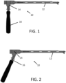
- the instrument may include a handle configured to pivot in a direction along the longitudinal axis of the shaft of the instrument, such as shown in FIGS 1-2 . Additionally, the handle of the instrument may be configured to rotate around the shaft of the instrument while the shaft remains stationary, as shown in FIGS. 3-4 .
- instrument 10 includes a shaft 12, a sleeve 14, and a handle assembly 16 as shown in the drawings.
- shaft 12 includes implant attachment 2, hollow annulus 4, body portion 6, and cap 8.
- Implant attachment 2 is located at the distal end of shaft 12 and is configured to detachably connect to an implant (e.g., a spinal fusion implant).
- Cap 8 is threadably connected to the proximal end of shaft 12, with body portion 6 (i.e., slotted portion) is located adjacent to cap 8.
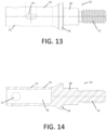
- Body portion 6 includes a distal portion 61, an intermediate section 62-63, a proximal portion 64, and a plurality of slots that are radially disposed around shaft 11, as best shown in FIGS. 8-9 .
- Sleeve 14 is positioned between proximal portion 64 and distal portion 61 such that the sleeve covers the majority of intermediate section 62-63.
- Intermediate section 62-63 are divided into first segment 63 and second segment 62.
- First segment 63 has a smaller outer diameter than distal portion 61
- second segment 62 has an outer diameter that increases in the distal direction along the longitudinal axis defined by body portion 6, the body portion being coaxially aligned with the shaft of instrument 10.
- First segment 63 includes normal slots 65, and second segment 62 includes diagonal slots 66. These slots are radially disposed around the first and second segments, respectively.
- normal slots 65 may extend into body portion 6 along a first direction that is perpendicular to the longitudinal axis defined by the body portion, and diagonal slots extend into the body portion along a second direction that is diagonal to the longitudinal axis of the body portion.
- First segment 63 and second segment 62 include any number of slots such that the first and second segments may have an equal or unequal number of slots.
- first segment 63 and second segment 62 may each have eight slots that are equally dispersed around first segment 63 and second segment 62, respectively.
- the location of the normal slots 65 and diagonal slots 66 may be aligned such that the normal slots and the diagonal slots are located at 45°, 90°, 135°, 180°, 225°, 270°, 315°, or 360° around body portion 6.
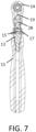
- Sleeve 14 includes a central anulus 25 that wraps around body portion 6 and an extension portion 21 that extends away from body portion 6, as best shown in FIGS. 5-7 and 10-11.
- Sleeve 14 is rotatably disposed around body portion 6 adjacent to cap 8, with the cap acting to hold the sleeve longitudinally in place.
- Extension portion 21 includes a cavity 23 and an aperture 27.
- Cavity 23 extends into central anulus 25 such that the cavity and the central anulus are in communication with each other. Cavity 23 is configured to receive a portion of handle assembly 16 such that that portion of the handle assembly can slide and pivot within the sleeve (discussed in more detail below).
- aperture 27 extends through both sides of the extension portion and through cavity 23.
- handle assembly 16 includes a handgrip 11, a connector 13, an actuator 17, and a positioning tip 19.
- Handgrip 11 connects to positioning tip 19 via connector 13, and the positioning tip is partially disposed within connector 13.
- Handgrip 11 is threadably attached to connector 13 opposite to positioning tip 19 and adjacent to a backstop 74 on connector 13.
- Connector 13 has a hollow chamber 76 configured to receive positioning tip 19 and a spring 15 such that the positioning tip can slide between different locations therein.
- Actuator 17 is slidably disposed around hollow chamber 76 of connector 13 and connected to positioning tip 19 by an actuator pin 36 positioned within a hole 54 in actuator 17 and an elongated hole 73 of connector 13 and a bottom hole 34 of positioning tip 19 when such holes are aligned, as shown in FIG. 6 .
- actuator pin 36 is disposed therein.
- Spring 15 has open-coil helical springs wound to resist compression and housed within hollow chamber 76 of connector 13 between positioning tip 19 and connector 13 such that the spring may exert a force on both the positioning tip and connector 13. In this manner, spring 15 is configured to push positioning tip 19 toward body portion 6.
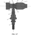
- positioning tip 19 is slidably disposed within cavity 23 and pivotably connected to extension portion 21 by pivot pin 28 positioned within slot 42 of positioning tip 19 and top hole 71 of connector 13 and aperture 27 when the slot and the aperture and the slot hole are in communication with each other as shown in FIG. 6 and 19 .
- Cavity 23 has an hourglass-like shape with opposite ends defining wider openings than a narrow region therebetween.
- aperture 27 may be located at this narrow region of cavity 23, as shown in FIG. 10 . Under such an arrangement, positioning tip 19 is provided space to pivot within cavity 23 about pivot pin 28, which defines the pivot point of handgrip 11.
- Normal slots 65 and diagonal slots 66 are configured to receive a portion of positioning tip 19.
- positioning tip 19 has first end 46 that has a smaller width and thickness than the remainder of the positioning tip such that the pointed end can be positioned within either a normal slot 65 or diagonal slot 66.
- anulus 25 of sleeve 14 has a cross sectional profile that mirrors a cross-sectional profile of intermediate section 62-63 such that any change in the outer diameter of the intermediate section corresponds to a change in the inner diameter of the annulus.
- Cavity 23 of sleeve 14 is in communication with at least one normal slot 65 and one diagonal slot 66 at various positions around body portion 6. In this manner, sleeve 14 may be configured to align positioning tip 19 with normal slots 65 and/or diagonal slots 66 for insertion therein.
- attachment tip 2 is configured to change the orientation of the implant attached thereon between a non-angled position to an angled position with respect to the longitudinal axis of the shaft of the instrument and/or the body portion of the handle assembly.
- Attachment tip may also be a modular attachment mechanism configured to attach to various implants of different shapes, sizes, and structure.
- an attachment mechanism located at the tip of instrument 10 may be capable of pivoting between two or more positions. In such instances, an attached implant may be tilted as the attachment mechanism pivots to and angled position with respect to the longitudinal axis of the shaft of the instrument.
- the attachment mechanism may releasably attach to an implant via components that hook or clamp together.
- an inner shaft may extend from attachment tip 2 and threadably connect to an implant.
- the present invention relates to a kit that may include a surgical instrument having a rotatable and pivotable handle, such as handgrip 11, along with implants, for example, but no limited to, spinal implants of various shapes and sizes.
- the kit may also include additional surgical tools such as retractors and cutting tools that may be used in a surgical procedure.
- the present disclosure relates to a method of pivoting a handle of a surgical instrument along the longitudinal axis of the shaft of the instrument.
- handgrip 11 may pivot from a first position to a second position by retracting positioning tip 19 away from a normal slot 65 such that spring 15 is compressed within hollow chamber 76 of connector 13 by pulling actuator 17 toward backstop 74 and holding the actuator in this retracted position.
- connector 13 may be tilted by pulling handgrip 11 proximally such that first end 46 of positioning tip 19 pivots about pivot pin 28 toward the distal tip of instrument 10 within cavity 23 of sleeve 14 as the handgrip pivots away from the distal tip of the instrument.
- pulling handgrip 11 in a proximal direction causes positioning tip 19, connector 13, and handgrip to pivot about pivot pin 28 such that the central axis of the connector becomes diagonal (i.e., oblique) to the longitudinal axis of body portion 6, as shown in FIG. 19 .
- the diagonal position of handgrip 11 may be secured by releasing actuator 17 such that spring 15 pushes first end 46 of positioning tip 19 into a diagonal slot 66 that is aligned with cavity 23 of sleeve 14.
- Handgrip 11 may pivot back to the previous orientation by repeating the foregoing steps but instead pushing handgrip 11 toward the distal tip of instrument 10 such that the central axis of the handgrip and connector 70 become orthogonal to the longitudinal axis of body portion 6 and/or the shaft of the instrument, as shown in FIG. 17 . In this manner, handgrip 11 may be pivoted from an orthogonal position to a diagonal position and back when in a disengaged state. This provides the advantage of allowing medical personnel to change the angle in which a handle, such as handgrip 11, extends from a surgical instrument to best suit a surgical procedure.
- handgrip 11 may also pivot from the orthogonal position to another oblique position, i.e., a third position (not shown), where connector 13 is tilted by pushing the handgrip distally such that first end 46 of positioning tip 19 pivots about pivot pin 28 away from the distal tip of instrument 10 within cavity 23 of sleeve 14 as the handgrip pivots toward the distal tip of the instrument.
- body portion 6 of instrument 10 may include a third set of diagonal slots (not shown) disposed proximal to normal slots 65 and configured to receive first end 46 to allow handgrip 11 to be fixed in the third position.
- an implant attached to instrument 10, such as implant 3 may be positioned such that the longitudinal axis of the implant is oblique to the longitudinal axis of body portion 6. In this manner, medical personnel can adjust the orientation of the implant and handgrip in a way that best facilitates implantation of the implant.
- the present disclosure relates to a method of rotating a handle of a surgical instrument around the longitudinal axis of the shaft of the instrument.
- handgrip 11 may rotate from a first location to a second location by retracting positioning tip 19 away from body portion 6 such that spring 15 is compressed within hollow chamber 76 of connector 13 by pulling actuator 17 toward backstop 74 and holding the actuator in this retracted position.
- handgrip 11 may be rotated by moving handgrip 11 around body portion 6, as shown in FIGS. 3-4 .
- handgrip 11 may be rotated and secured to different locations around body portion 6.
- angle slots 66 and non-angled slots 65 may be disposed at eight different locations around body portion 6 and spaced apart by 45°, but other embodiments may have more or less locations.
- the second location of handgrip 11 may be secured by releasing actuator 17 such that spring 15 pushes first end 46 of positioning tip 19 into either a normal slot 65 or a diagonal slot 66 aligned with cavity 23 of sleeve 14.
- Handgrip 11 may be rotated back a previous location or further rotated around body portion 6 by repeating the foregoing steps and rotating handgrip 11 such that the positioning tip 19 aligns with a slot at a different location around body portion 6, as shown in FIGS. 17-19 .
- handgrip 11 may be relocated by rotating the handle around body portion 6 to various locations. This provides the advantage of allowing medical personnel to change the location in which a handle, such as handgrip 11, extends from a surgical instrument to best suit a surgical procedure.
- the present disclosure relates to a method of rotating and pivoting a handle of a surgical instrument around and along the longitudinal axis of the shaft instrument.
- handgrip 11 may rotate from a first location to a second location and pivot from a first position to a second position by retracting positioning tip 19 away from body portion 6 such that spring 15 is compressed within hollow chamber 76 of connector 13 by pulling actuator toward backstop 74 and holding the actuator in this retracted position.
- handgrip 11 may be rotated around and pivoted along body portion 6 by moving handgrip 11 around and along the longitudinal axis of the body portion and/or the shaft of instrument 10, as shown in FIGS. 3-4 and 1-2 , respectively.
- handgrip 11 may be secured by releasing actuator 17 such that spring 15 pushes pointed end 46 of positioning tip 19 into a slot 65, 66 disposed in body portion 6.
- Handgrip 11 may be reoriented back to the previous position or further reorientated about body portion 6 by repeating the foregoing steps. In this manner, handgrip 11 may be oriented by rotating and pivoting the handle around body portion 6 to various positions and angles. This provides the advantage of allowing medical personnel to select an orientation of handgrip 11 that best suits the surgical procedure.
- the present disclosure relates to a method of pivoting a handle of a surgical instrument along the longitudinal axis of the shaft instrument and titling the orientation of an implant attached to the tip of the instrument.
- handgrip 11 may reorient to a diagonal position by disengaging positioning pin 19 and pivoting the handgrip as described above.
- implant 3 may be connected to instrument 10 by attaching implant to the tip of the instrument via an attachment mechanism. Once implant 3 has been attached to instrument 10, implant 3 may be reoriented by tilting the implant such that the longitudinal axis of the implant is diagonal to the longitudinal axis of the shaft of the instrument, as shown in FIG. 21 .
- the instrument may engage or attach to an implant at different locations on the implant such that the implant may be oriented in a non-angled or angled position relative to the instrument. In this manner, handgrip 10 and implant 3 can be oriented to better suit an angled approach.
Landscapes
- Health & Medical Sciences (AREA)
- Engineering & Computer Science (AREA)
- Biomedical Technology (AREA)
- Orthopedic Medicine & Surgery (AREA)
- Transplantation (AREA)
- Neurology (AREA)
- Heart & Thoracic Surgery (AREA)
- Oral & Maxillofacial Surgery (AREA)
- Cardiology (AREA)
- Vascular Medicine (AREA)
- Life Sciences & Earth Sciences (AREA)
- Animal Behavior & Ethology (AREA)
- General Health & Medical Sciences (AREA)
- Public Health (AREA)
- Veterinary Medicine (AREA)
- Physical Education & Sports Medicine (AREA)
- Surgical Instruments (AREA)
- Prostheses (AREA)
Applications Claiming Priority (1)
| Application Number | Priority Date | Filing Date | Title |
|---|---|---|---|
| US202363531390P | 2023-08-08 | 2023-08-08 |
Publications (1)
| Publication Number | Publication Date |
|---|---|
| EP4505981A1 true EP4505981A1 (fr) | 2025-02-12 |
Family
ID=92264130
Family Applications (1)
| Application Number | Title | Priority Date | Filing Date |
|---|---|---|---|
| EP24193328.2A Pending EP4505981A1 (fr) | 2023-08-08 | 2024-08-07 | Poignée pivotante latérale universelle |
Country Status (2)
| Country | Link |
|---|---|
| US (1) | US12551356B2 (fr) |
| EP (1) | EP4505981A1 (fr) |
Citations (6)
| Publication number | Priority date | Publication date | Assignee | Title |
|---|---|---|---|---|
| US20070233150A1 (en) * | 2006-03-30 | 2007-10-04 | Jason Blain | Drill guide with rotating handle |
| FR2977474A1 (fr) * | 2011-07-08 | 2013-01-11 | Kasios | Cage intersomatique, notamment du type transforaminal |
| EP2735287A1 (fr) * | 2012-11-21 | 2014-05-28 | K2M, Inc. | Instrument d'insertion d'implant vertébral réglable |
| US20180360621A1 (en) * | 2017-01-26 | 2018-12-20 | Soojung Moon | Inserting device of cage for disc space between vertebrae |
| WO2020185032A2 (fr) * | 2019-03-13 | 2020-09-17 | 큐렉소 주식회사 | Dispositif poignée d'outil chirurgical |
| US10881530B2 (en) * | 2017-04-28 | 2021-01-05 | Warsaw Orthopedic, Inc. | Surgical instrument and method |
Family Cites Families (73)
| Publication number | Priority date | Publication date | Assignee | Title |
|---|---|---|---|---|
| US4716894A (en) | 1986-08-27 | 1988-01-05 | Zimmer, Inc. | Acetabular cup inserting instrument |
| US5284483A (en) | 1992-09-16 | 1994-02-08 | Zimmer, Inc. | Acetabular cup inserting instrument |
| DE4416377A1 (de) | 1993-05-15 | 1994-11-17 | Ueth & Haug Gmbh | Vorrichtung zum Austrennen von Endoprothesen |
| US5584837A (en) | 1993-08-13 | 1996-12-17 | Petersen; Thomas D. | Acetabular cup inserter for orthopedic |
| GB2299758B (en) | 1995-04-10 | 1998-07-22 | Finsbury | Surgical tool |
| DE29607026U1 (de) | 1996-04-18 | 1996-07-04 | Aesculap Ag, 78532 Tuttlingen | Chirurgischer Drehmomentschlüssel |
| ES2164548B1 (es) | 1999-08-05 | 2003-03-01 | Probitas Pharma Sa | Dispositivo para la dosificacion de masa fraguable para vertebroplastia y otros tratamientos oseos similares. |
| US6238435B1 (en) | 2000-03-10 | 2001-05-29 | Bristol-Myers Squibb Co | Assembly tool for prosthetic implant |
| US6524238B2 (en) | 2000-12-20 | 2003-02-25 | Synthes Usa | Universal handle and method for use |
| JP4234443B2 (ja) | 2001-05-15 | 2009-03-04 | ウォーソー・オーソペディック・インコーポレーテッド | 後横方向椎間板空間アプローチ法用の装置及び技術 |
| ATE363251T1 (de) | 2002-03-11 | 2007-06-15 | Spinal Concepts Inc | Einrichtung zum einsetzen von wirbelsäulenimplantaten |
| US7799086B2 (en) | 2002-04-25 | 2010-09-21 | Zimmer Technology, Inc. | Modular bone implant, tools, and method |
| AU2003219465A1 (en) | 2002-04-30 | 2003-11-17 | Precimed S.A. | Reamer spindle for minimally invasive joint surgery |
| US7008430B2 (en) | 2003-01-31 | 2006-03-07 | Howmedica Osteonics Corp. | Adjustable reamer with tip tracker linkage |
| DE10324844A1 (de) | 2003-04-01 | 2004-12-23 | Tuebingen Scientific Surgical Products Gmbh | Chirurgisches Instrument mit Instrumentengriff und Nullpunkteinstellung |
| US7186257B2 (en) | 2003-06-09 | 2007-03-06 | Jun Hyun Kim | Auxiliary apparatus for inserting a pin into a broken bone |
| US7488327B2 (en) | 2004-04-12 | 2009-02-10 | Synthes (U.S.A.) | Free hand drill guide |
| US9155546B2 (en) | 2007-12-21 | 2015-10-13 | Smith & Nephew, Inc. | Surgical aimer |
| US9173694B2 (en) | 2009-09-18 | 2015-11-03 | Spinal Surgical Strategies, Llc | Fusion cage with combined biological delivery system |
| US10973656B2 (en) | 2009-09-18 | 2021-04-13 | Spinal Surgical Strategies, Inc. | Bone graft delivery system and method for using same |
| US20170238984A1 (en) | 2009-09-18 | 2017-08-24 | Spinal Surgical Strategies, Llc | Bone graft delivery device with positioning handle |
| US8906028B2 (en) | 2009-09-18 | 2014-12-09 | Spinal Surgical Strategies, Llc | Bone graft delivery device and method of using the same |
| US10245159B1 (en) | 2009-09-18 | 2019-04-02 | Spinal Surgical Strategies, Llc | Bone graft delivery system and method for using same |
| US9186193B2 (en) | 2009-09-18 | 2015-11-17 | Spinal Surgical Strategies, Llc | Fusion cage with combined biological delivery system |
| US9629729B2 (en) | 2009-09-18 | 2017-04-25 | Spinal Surgical Strategies, Llc | Biological delivery system with adaptable fusion cage interface |
| US8685031B2 (en) | 2009-09-18 | 2014-04-01 | Spinal Surgical Strategies, Llc | Bone graft delivery system |
| US9060877B2 (en) | 2009-09-18 | 2015-06-23 | Spinal Surgical Strategies, Llc | Fusion cage with combined biological delivery system |
| US8709086B2 (en) | 2009-10-15 | 2014-04-29 | Globus Medical, Inc. | Expandable fusion device and method of installation thereof |
| US9155628B2 (en) | 2009-10-15 | 2015-10-13 | Globus Medical, Inc. | Expandable fusion device and method of installation thereof |
| US11564807B2 (en) | 2009-10-15 | 2023-01-31 | Globus Medical, Inc. | Expandable fusion device and method of installation thereof |
| US8685098B2 (en) | 2010-06-25 | 2014-04-01 | Globus Medical, Inc. | Expandable fusion device and method of installation thereof |
| US9216095B2 (en) | 2009-10-15 | 2015-12-22 | Globus Medical, Inc. | Expandable fusion device and method of installation thereof |
| US8556979B2 (en) | 2009-10-15 | 2013-10-15 | Globus Medical, Inc. | Expandable fusion device and method of installation thereof |
| US11103366B2 (en) | 2009-10-15 | 2021-08-31 | Globus Medical, Inc. | Expandable fusion device and method of installation thereof |
| US10806596B2 (en) | 2009-10-15 | 2020-10-20 | Globus Medical, Inc. | Expandable fusion device and method installation thereof |
| US8679183B2 (en) | 2010-06-25 | 2014-03-25 | Globus Medical | Expandable fusion device and method of installation thereof |
| US20140163682A1 (en) | 2012-12-11 | 2014-06-12 | Expandable Vertebral Implant | Expandable Vertebral Implant |
| US10327917B2 (en) | 2009-10-15 | 2019-06-25 | Globus Medical, Inc. | Expandable fusion device and method of installation thereof |
| US8062375B2 (en) | 2009-10-15 | 2011-11-22 | Globus Medical, Inc. | Expandable fusion device and method of installation thereof |
| US11344430B2 (en) | 2009-10-15 | 2022-05-31 | Globus Medical, Inc. | Expandable fusion device and method of installation thereof |
| US10098758B2 (en) | 2009-10-15 | 2018-10-16 | Globus Medical, Inc. | Expandable fusion device and method of installation thereof |
| US8870880B2 (en) | 2010-04-12 | 2014-10-28 | Globus Medical, Inc. | Angling inserter tool for expandable vertebral implant |
| US9597200B2 (en) | 2010-06-25 | 2017-03-21 | Globus Medical, Inc | Expandable fusion device and method of installation thereof |
| US9078672B1 (en) | 2010-11-05 | 2015-07-14 | Greatbatch Medical S.A. | Carbon reamer handle |
| EP2830542B1 (fr) | 2012-03-28 | 2021-10-27 | Innova Spinal Technologies, LLC | Implant intervertébral expansible |
| US10299934B2 (en) | 2012-12-11 | 2019-05-28 | Globus Medical, Inc | Expandable vertebral implant |
| US10350081B2 (en) | 2012-12-11 | 2019-07-16 | Globus Medical, Inc. | Expandable vertebral implant |
| US9782265B2 (en) | 2013-02-15 | 2017-10-10 | Globus Medical, Inc | Articulating and expandable vertebral implant |
| US9936960B2 (en) * | 2014-11-20 | 2018-04-10 | Symmetry Medical Manufacturing, Inc. | Detachable orthopaedic reamer handle |
| US10376377B2 (en) | 2015-07-17 | 2019-08-13 | Globus Medical, Inc. | Intervertebral spacer and plate |
| US9956087B2 (en) | 2015-07-17 | 2018-05-01 | Globus Medical, Inc | Intervertebral spacer and plate |
| US9987144B2 (en) | 2015-07-17 | 2018-06-05 | Globus Medical, Inc. | Intervertebral spacer and plate |
| US11045326B2 (en) | 2015-07-17 | 2021-06-29 | Global Medical Inc | Intervertebral spacer and plate |
| US10016282B2 (en) | 2015-07-17 | 2018-07-10 | Globus Medical, Inc. | Intervertebral spacer and plate |
| US10610376B2 (en) | 2015-10-16 | 2020-04-07 | Warsaw Orthopedic, Inc. | Expandable spinal implant system and method |
| US10327787B2 (en) | 2015-12-28 | 2019-06-25 | Nuvasive, Inc | Adjustable depth drill guide |
| US10070971B2 (en) | 2016-01-22 | 2018-09-11 | Warsaw Orthopedic, Inc. | Surgical instrument and method |
| US10137006B2 (en) | 2016-01-28 | 2018-11-27 | Warsaw Orthopedic, Inc. | Geared cam expandable interbody implant and method of implanting same |
| US10631884B2 (en) | 2017-06-05 | 2020-04-28 | Conmed Corporation | Multi-barrel drill guide |
| WO2019178575A1 (fr) | 2018-03-16 | 2019-09-19 | Benvenue Medical, Inc. | Instrumentation articulée et et ses procédés d'utilisation |
| US11612501B2 (en) | 2018-10-19 | 2023-03-28 | Tightline Development, LLC. | Hip and knee joint stem explant system and methods of using the same |
| US11628023B2 (en) | 2019-07-10 | 2023-04-18 | Globus Medical, Inc. | Robotic navigational system for interbody implants |
| US11364130B2 (en) | 2020-09-01 | 2022-06-21 | Warsaw Orthopedic, Inc. | Spinal implant system and method |
| US12318308B2 (en) | 2020-11-05 | 2025-06-03 | Warsaw Orthopedic, Inc. | Dual expandable inter-body device |
| US11564724B2 (en) | 2020-11-05 | 2023-01-31 | Warsaw Orthopedic, Inc. | Expandable inter-body device, system and method |
| US11291554B1 (en) | 2021-05-03 | 2022-04-05 | Medtronic, Inc. | Unibody dual expanding interbody implant |
| US11638653B2 (en) | 2020-11-05 | 2023-05-02 | Warsaw Orthopedic, Inc. | Surgery instruments with a movable handle |
| US11833059B2 (en) | 2020-11-05 | 2023-12-05 | Warsaw Orthopedic, Inc. | Expandable inter-body device, expandable plate system, and associated methods |
| US11285014B1 (en) | 2020-11-05 | 2022-03-29 | Warsaw Orthopedic, Inc. | Expandable inter-body device, system, and method |
| US11517443B2 (en) | 2020-11-05 | 2022-12-06 | Warsaw Orthopedic, Inc. | Dual wedge expandable implant, system and method of use |
| US12121453B2 (en) | 2020-11-05 | 2024-10-22 | Warsaw Orthopedic, Inc. | Dual wedge expandable implant with eyelets, system, and method of use |
| US11376134B1 (en) | 2020-11-05 | 2022-07-05 | Warsaw Orthopedic, Inc. | Dual expanding spinal implant, system, and method of use |
| US11395743B1 (en) | 2021-05-04 | 2022-07-26 | Warsaw Orthopedic, Inc. | Externally driven expandable interbody and related methods |
-
2024
- 2024-08-06 US US18/795,783 patent/US12551356B2/en active Active
- 2024-08-07 EP EP24193328.2A patent/EP4505981A1/fr active Pending
Patent Citations (6)
| Publication number | Priority date | Publication date | Assignee | Title |
|---|---|---|---|---|
| US20070233150A1 (en) * | 2006-03-30 | 2007-10-04 | Jason Blain | Drill guide with rotating handle |
| FR2977474A1 (fr) * | 2011-07-08 | 2013-01-11 | Kasios | Cage intersomatique, notamment du type transforaminal |
| EP2735287A1 (fr) * | 2012-11-21 | 2014-05-28 | K2M, Inc. | Instrument d'insertion d'implant vertébral réglable |
| US20180360621A1 (en) * | 2017-01-26 | 2018-12-20 | Soojung Moon | Inserting device of cage for disc space between vertebrae |
| US10881530B2 (en) * | 2017-04-28 | 2021-01-05 | Warsaw Orthopedic, Inc. | Surgical instrument and method |
| WO2020185032A2 (fr) * | 2019-03-13 | 2020-09-17 | 큐렉소 주식회사 | Dispositif poignée d'outil chirurgical |
Also Published As
| Publication number | Publication date |
|---|---|
| US12551356B2 (en) | 2026-02-17 |
| US20250049583A1 (en) | 2025-02-13 |
Similar Documents
| Publication | Publication Date | Title |
|---|---|---|
| US12053213B2 (en) | Modular surgical instruments and related methods | |
| AU2023282316B2 (en) | Sagittal balance systems and methods of use thereof | |
| US10881527B2 (en) | Vertebral body replacement device and method for use to maintain a space between two vertebral bodies within a spine | |
| US12383323B2 (en) | Inserter guide and driver system | |
| JP2024514537A (ja) | 拡張可能な脊椎固定インプラントおよび挿入デバイス | |
| EP1832248B1 (fr) | Poignée déportée pour composants | |
| AU2015302333B2 (en) | Minimally disruptive retractor and associated methods for spinal surgery | |
| US20070191857A1 (en) | Spinal disc replacement surgical instrument and methods for use in spinal disc replacement | |
| EP3738518A1 (fr) | Rétracteur minimalement perturbateur et procédés associés pour la chirurgie des vertèbres | |
| EP2695582B1 (fr) | Instrument chirurgical | |
| CN101951847A (zh) | 脊柱转移工具 | |
| JP2007521886A (ja) | 脊椎手術のためのシステムおよび方法 | |
| WO2016044824A1 (fr) | Implant intervertébral configurable | |
| US20060235418A1 (en) | Method and device for preparing a surface for receiving an implant | |
| EP3684269B1 (fr) | Écarteur chirurgical monté sur le patient | |
| AU2013262606B2 (en) | Vertebral body replacement device and method for use of the device with the inserting tool | |
| EP4505981A1 (fr) | Poignée pivotante latérale universelle | |
| US20240009003A1 (en) | Instrument holder assemblies and retractors for spinal surgery procedures | |
| WO2022198134A1 (fr) | Ensembles porte-instrument et écarteurs pour procédures de chirurgie rachidienne | |
| WO2026020017A1 (fr) | Systèmes de dilatateurs chirurgicaux multiportails et dispositifs et procédés associés | |
| WO2026013090A1 (fr) | Dispositifs vertébraux réglables et instruments de déploiement et de mesure associés |
Legal Events
| Date | Code | Title | Description |
|---|---|---|---|
| PUAI | Public reference made under article 153(3) epc to a published international application that has entered the european phase |
Free format text: ORIGINAL CODE: 0009012 |
|
| STAA | Information on the status of an ep patent application or granted ep patent |
Free format text: STATUS: THE APPLICATION HAS BEEN PUBLISHED |
|
| AK | Designated contracting states |
Kind code of ref document: A1 Designated state(s): AL AT BE BG CH CY CZ DE DK EE ES FI FR GB GR HR HU IE IS IT LI LT LU LV MC ME MK MT NL NO PL PT RO RS SE SI SK SM TR |
|
| RAP1 | Party data changed (applicant data changed or rights of an application transferred) |
Owner name: STRYKER CORPORATION |
|
| STAA | Information on the status of an ep patent application or granted ep patent |
Free format text: STATUS: REQUEST FOR EXAMINATION WAS MADE |
|
| 17P | Request for examination filed |
Effective date: 20250807 |
|
| GRAP | Despatch of communication of intention to grant a patent |
Free format text: ORIGINAL CODE: EPIDOSNIGR1 |
|
| STAA | Information on the status of an ep patent application or granted ep patent |
Free format text: STATUS: GRANT OF PATENT IS INTENDED |
|
| INTG | Intention to grant announced |
Effective date: 20260123 |