EP4506101A1 - Dispositif d'économie d'énergie pour machine-outil multitâche multisystème - Google Patents
Dispositif d'économie d'énergie pour machine-outil multitâche multisystème Download PDFInfo
- Publication number
- EP4506101A1 EP4506101A1 EP23933283.6A EP23933283A EP4506101A1 EP 4506101 A1 EP4506101 A1 EP 4506101A1 EP 23933283 A EP23933283 A EP 23933283A EP 4506101 A1 EP4506101 A1 EP 4506101A1
- Authority
- EP
- European Patent Office
- Prior art keywords
- axis
- unit
- spindle
- units
- relay
- Prior art date
- Legal status (The legal status is an assumption and is not a legal conclusion. Google has not performed a legal analysis and makes no representation as to the accuracy of the status listed.)
- Pending
Links
Images

Classifications
-
- G—PHYSICS
- G05—CONTROLLING; REGULATING
- G05B—CONTROL OR REGULATING SYSTEMS IN GENERAL; FUNCTIONAL ELEMENTS OF SUCH SYSTEMS; MONITORING OR TESTING ARRANGEMENTS FOR SUCH SYSTEMS OR ELEMENTS
- G05B19/00—Program-control systems
- G05B19/02—Program-control systems electric
- G05B19/18—Numerical control [NC], i.e. automatically operating machines, in particular machine tools, e.g. in a manufacturing environment, so as to execute positioning, movement or co-ordinated operations by means of program data in numerical form
-
- G—PHYSICS
- G05—CONTROLLING; REGULATING
- G05B—CONTROL OR REGULATING SYSTEMS IN GENERAL; FUNCTIONAL ELEMENTS OF SUCH SYSTEMS; MONITORING OR TESTING ARRANGEMENTS FOR SUCH SYSTEMS OR ELEMENTS
- G05B2219/00—Program-control systems
- G05B2219/30—Nc systems
- G05B2219/32—Operator till task planning
- G05B2219/32021—Energy management, balance and limit power to tools
-
- G—PHYSICS
- G05—CONTROLLING; REGULATING
- G05B—CONTROL OR REGULATING SYSTEMS IN GENERAL; FUNCTIONAL ELEMENTS OF SUCH SYSTEMS; MONITORING OR TESTING ARRANGEMENTS FOR SUCH SYSTEMS OR ELEMENTS
- G05B2219/00—Program-control systems
- G05B2219/30—Nc systems
- G05B2219/34—Director, elements to supervisory
- G05B2219/34306—Power down, energy saving
Definitions
- the present disclosure relates to electrical energy savings used in machine tools, and more specifically, to an apparatus and a method for realizing energy savings by blocking a standby power of an axis unit that is not being used for machining in a multi-axis system complex machine tool.
- a multi-axis system complex machine tool is provided with at least two axis units that rotate or transport a tool or a workpiece and performs various machining works such as milling, turning, and grinding process in a single machine tool by setting up the workpiece once.
- a computer numerically controlled (CNC) device to control the axis units is provided. Since the CNC device applied to a complex machine tool has many axis units subject to control, a CNC device having a concept of integrating multiple numerical control devices is applied.
- the CNC device of the multi-axis system complex machine tool is comprised of an axis unit that independently performs machining programs and a group consisting of a set of such axis units.
- a single axis system means that it performs a single machining program (G-Code) through an operation control of one or more axis units
- a multi-axis system means that a plurality of axis units is provided and one or more machining programs are simultaneously performed to process the workpiece.
- the workpiece and processing information should be shared between respective axis systems, and multi-axis systems should be operated simultaneously in multi-tasking ways to execute a complex (multi-tasking) machining work.
- the multi-axis system complex machine tool consists of several axis units that perform rotation or transport functions, and respective axis systems comprised of a plurality of axis units are driven and controlled by an independently provided power source.
- each system operates simultaneously and complexly to process the workpiece, but there should inevitably exist an axis unit not participating in the complex processing work to avoid conflicts in machining operations by respective axis units or due to a nature of the machining programs in consideration of an order of machining operations, or the like. Nevertheless, when the multi-axis system complex machine tool starts its operation, a standby power is always supplied to a driving part of each axis unit in preparation for a prompt operation at any time.
- such a standby power contributes to power consumption by maintaining a constant current value even if a corresponding axis unit is not operated.
- Patent Document 1 relates to an energy saving type numerical control device that minimizes a power consumption of the machine tool by controlling an acceleration and a deceleration speed of the transporting axis and an acceleration and a deceleration speed of the spindle.
- Patent Document 1 discloses a machining program part that transmits at least one command out of a position, a speed and an acceleration and a deceleration speed for driving a main spindle motor and a transporting motor in response to a processing cycle, and introduces a method of reducing the power consumption by calculating and controlling time constants of the respective commands included in each processing cycle in cooperation with the machining program part.
- this method only uses one of a friction torque of the main spindle, a load inertia and parameters of the main spindle motor to control the time constant that determines a target speed reaching time of a transporting axis unit or a rotation axis unit, which is nothing more than a solution for reducing the power consumption in part only during acceleration and deceleration process of the axis unit.
- Patent Document 1 Korean Patent Registration No. 10-1575144
- an object of the present disclosure is to provide an apparatus and a method for realizing energy savings by distinguishing an axis unit being used for a machining work and an unused axis unit in a multi-axis system complex machine tool and not supplying a standby power to a driver module that controls the unused axis unit, thereby reducing power consumption of the multi-axis system complex machine tool.
- an apparatus for realizing energy savings of a multi-axis system complex machine tool may include: a CNC control device 10, when executing a complex processing a workpiece, configured to constitute a plurality of processing condition groups that are a set of at least one axis units depending on whether the axis units can be used simultaneously without conflicts between the axis units according to processing conditions of the workpiece, recognize a specific processing condition group out of the plurality of processing condition groups in response to execution of the machining program, and transmit a processing condition group signal; and a power supply device 20 including a driver module unit 40 having a plurality of driver modules that drive an axis unit corresponding to the at least one processing condition group signal, and a relay unit 30 having a plurality of relays installed in numbers corresponding to the plurality of driver modules and to apply a standby power to the driver module that drives the axis unit of the processing condition group in response to the processing condition group signal.
- the axis unit may comprise:
- the milling spindle rotation axis unit (C3) may further include a milling division axis unit (B) that performs an angle division rotation function.
- the tool post (S4) may further include a tool post rotation axis unit (C4), as a rotation axis unit, that rotates a rotary tool mounted on the tool post (S4).
- a tool post rotation axis unit C4, as a rotation axis unit, that rotates a rotary tool mounted on the tool post (S4).
- an anti-vibration unit (S5) may be installed between the main spindle (S 1) and the sub-spindle (S2), wherein the anti-vibration unit (S5), as a feed unit, includes an anti-vibration axis unit (W1) that moves the anti-vibration unit in the Z-axis direction.
- the processing condition group of the CNC control device 10 may include at least one or more groups out of:
- the CNC control device 10 may include a machining program unit 11 that controls respective axis units to execute a machining work of the workpiece, a programmable logic controller (PLC) 12 that recognizes a processing condition group including the axis unit to be used by analyzing a machining program of the machining program unit 11, and an I/O module 13 that outputs a relay drive signal of the power supply device 20 according to the processing condition group signal provided from the PLC control unit 12.
- PLC programmable logic controller
- the machining program unit 11 may be configured to derive an M code included in the machining program and applies an axis unit signal to be used according to the M code to the PLC control unit 12.
- the machining program unit 11 may be configured to apply signals contained in the machining program on the rotation axis units (C1, C2, C3, C4) of the spindles (S1, S2, S3) and the tool post(S4) to be used to the PLC control unit 12, wherein the PLC control unit 12 is configured to identify the processing condition group including the signals of the rotation axis units (C1, C2, C3, C4) and apply the same to the I/O module.
- each relay of the relay unit 30 may be a B-contact type relay whose contact is released in response to the processing condition group signal applied from the CNC control device 10, wherein when the relay is in an A contact, a standby power is blocked to the axis unit driver module of the corresponding processing condition group, and when the relay is in a B contact, the standby power is supplied to the axis unit driver module of the relevant processing condition group.
- the relay unit 30 may comprise:
- the relay unit 30 may further includes a sixth relay 36 connected to the sixth driver module 46 that supplies or blocks the standby power to an arm axis unit of a tool changer, a shift axis unit of the tool changer, an axis unit of a first tool magazine axis system, and an axis unit of a second tool magazine of the multi-axis system complex machine tool.
- a sixth relay 36 connected to the sixth driver module 46 that supplies or blocks the standby power to an arm axis unit of a tool changer, a shift axis unit of the tool changer, an axis unit of a first tool magazine axis system, and an axis unit of a second tool magazine of the multi-axis system complex machine tool.
- the present disclosure may reduce power consumption by distinguishing between an axis unit being used for a machining work and an unused axis unit in a multi-axis system complex machine tool and by not supplying a standby power to a driver module that controls the unused axis unit.
- an axis unit collectively refers to a rotation axis unit and a feed axis unit, unless specifically limited.
- Each axis unit may include a servomotor that is controlled by commands from a numerical control device or a computerized numerical control (CNC) device 10 of a multi-axis complex machine tool.
- the servomotor may serve to rotate or feed a relevant axis unit by high-speed rotation or angle division.
- each servomotor constituting each axis unit may be provided with a driver module that receives power from a power supply device 20 and controls rotation of the servomotor.
- Each driver module may be controlled by a command of the numerical control device or the CNC control device 10.
- the present disclosure exemplarily illustrates a multi-axis system complex machine tool including a plurality of rotation axis units and feed axis units.
- the multi-axis system complex machine tools are necessarily equipped with such rotation axis units and feed axis units.
- it may be configured by omitting or adding some rotation axis units and feed axis units.
- FIG. 2 is a schematic conceptual diagram configuring an axis unit for an axis system of a multi-axis system complex machine tool according to an exemplary embodiment of the present disclosure.
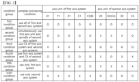
- FIG. 3 is a table illustrating a classification of an axis system of a multi-axis system complex machine tool and a complex processing condition group for each axis system according to an exemplary embodiment of the present disclosure.
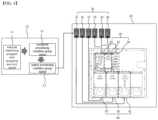
- FIG. 4 is a diagram illustrating a configuration of a driver module for each axis system of a multi-axis system complex machine tool according to an exemplary embodiment of the present disclosure.
- FIG. 5 is an exemplary machining program that applies power to at a driver module of an axis unit through a machining program according to an exemplary embodiment of the present disclosure.
- FIG. 6 is a table illustrating an axis unit allocated for each relay and each driver module according to an exemplary embodiment of the present disclosure.
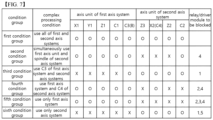
- FIG. 7 is a table illustrating a rely and a driver module that are blocked for each condition group and a complex processing condition according to an exemplary embodiment of the present disclosure.
- a multi-axis system complex machine tool may be comprised of following axis units.
- a first axis system may include a main spindle (S1) installed in the multi-axis system complex machine tool in a Z-axis direction, wherein the main spindle (S1) includes a main spindle rotation axis unit (C1) that rotates about a rotation axis in the Z-axis direction.
- S1 main spindle
- C1 main spindle rotation axis unit
- the first axis system may include a milling spindle (S3) installed in a direction perpendicular to a rotation axis of the main spindle rotation axis system (C1), wherein the milling spindle (S3), as a feed axis unit, includes a milling spindle X-axis unit (X1) that moves the milling spindle (S3) in a X-axis direction, a milling spindle Y-axis unit (Y1) that moves the milling spindle (S3) in a Y-axis direction, and a milling spindle Z-axis unit (Z1) that moves the milling spindle (S3) in a Z-axis direction, and wherein the milling spindle (S3), as a rotation axis unit, includes a milling spindle rotation axis unit (C3) that rotates the milling spindle (S3) about a rotation axis in the X-axis direction.
- X1 milling
- the milling spindle rotation axis unit (C3) may include a milling division axis unit (B) that performs an angle division rotation function according to a type of the multi-axis system complex machine tool.
- a second axis system may include a sub-spindle (S2) installed at a position opposite to the main spindle (S 1) in the multi-axis system complex machine tool in the Z-axis direction, wherein the sub-spindle (S2) includes a sub-spindle rotation axis unit (C2) that rotates about a rotation axis in the Z-axis direction and as a feed axis unit, a sub-spindle feed axis unit (C3) that moves the sub-spindle (S2) in the Z-axis direction.
- the sub-spindle (S2) includes a sub-spindle rotation axis unit (C2) that rotates about a rotation axis in the Z-axis direction and as a feed axis unit, a sub-spindle feed axis unit (C3) that moves the sub-spindle (S2) in the Z-axis direction.
- the second axis system may include a tool post (S4) installed in a direction perpendicular to the rotation axes of the main spindle (S 1) and the sub-spindle (S2), wherein the tool post (S4), as a feed axis unit, includes a tool post X-axis unit (X2) that moves the tool post (S4) in the direction perpendicular to the rotation axes of the main spindle (S 1) and the sub-spindle (S2) and a tool post Z-axis unit (Z2) that moves the tool post (S4) in the Z-axis direction.
- X2 tool post X-axis unit
- Z2 tool post Z-axis unit
- the tool post (S4) may further include a tool post rotation axis unit (C4), as a rotation axis unit, that rotates a rotary tool mounted on the tool post (S4) according to a type of the multi-axis system complex machine tool.
- C4 tool post rotation axis unit
- the second axis system may include an anti-vibration unit (S5) installed between the main spindle (S 1) and the sub-spindle (S2), wherein the anti-vibration unit (S5), as a feed ais unit, includes an anti-vibration axis unit (W1) that moves the anti-vibration unit in the Z-axis direction.
- S5 installed between the main spindle (S 1) and the sub-spindle (S2)
- W1 anti-vibration axis unit
- the anti-vibration axis unit (W1) may be a feed axis unit that may be excluded depending on whether the anti-vibration unit (S5) is installed or not, since the installation of the anti-vibration unit (S5) may be omitted depending on the type of multi-axis system complex machine tool.
- the above-mentioned axis unit processing may be divided into a plurality of processing condition groups that consists of at least one axis unit depending on whether or not the axis unit may be simultaneously used while avoiding collisions between axis units depending on the processing conditions of the workpiece when executing a complex machining of the workpiece.
- the axis unit may be divided into six processing condition groups as follows.
- a first condition group may be a complex processing condition that uses all of the feed axis units (X1, Y1, Z1, Z3, X2, Z2) of a first axis system and a second axis system and rotation axis units (C1, C2, C3, C4).
- the first condition group refers to a working condition that processes a workpiece by simultaneously or selectively using the main spindle (S 1), the sub-spindle (S2), the milling spindle (S3), and the tool post (S4) of a multi-axis system complex machine tool.
- a second condition group may be a complex processing condition that uses all of the feed axis units (X1, Y1, Z1) of the first axis system and rotation axis units (C1, C3), and uses only the sub-spindle rotation axis unit (C2) of the sub-spindle (S2) in the second axis system.
- the second condition group refers to a working condition that processes a workpiece by simultaneously or selectively using the main spindle (S1), the sub-spindle (S2) and the milling spindle (S3) of a multi-axis system complex machine tool.
- a third condition group may be a complex processing condition that uses all of the feed axis units (Z3, X2, Z2) of the second axis system and rotation axis units (C2, C4), and uses only the milling spindle rotation axis unit (C3) of the milling spindle (S3) in the first axis system.
- the third condition group refers to a working condition that processes a workpiece by simultaneously or selectively using the sub-spindle (S2), the milling spindle (S3) and the tool post (S4) of a multi-axis system complex machine tool.
- a fourth condition group may be a complex processing condition that uses all of the feed axis units (X1, Y1, Z1) of the first axis system and rotation axis units (C1, C3), and uses only the tool post X-axis unit (X2), a feed axis unit, of the tool post (S4) in the second axis system.
- the second condition group refers to a working condition that processes a workpiece by simultaneously or selectively using the main spindle (S 1), the milling spindle (S3) and the tool post (S4) of a multi-axis system complex machine tool.
- a fifth condition group may be a complex processing condition that uses only the feed axis units (X1, Y1, Z1) of the first axis system and rotation axis units (C1, C3).
- the fifth condition group refers to a working condition that processes a workpiece by simultaneously or selectively using the main spindle (S1) and the milling spindle (S3) of the multi-axis system complex machine tool.
- a sixth condition group may be a complex processing condition that uses only the feed axis units (Z3, X2, Z2) of the second axis system and rotation axis units (C2, C4).
- the sixth condition group refers to a working condition that processes a workpiece by simultaneously or selectively using the sub-spindle (S2) and the tool post (S4) of a multi-axis system complex machine tool.
- the multi-axis system complex machine tool may include a CNC control device 10 that recognizes the processing condition group in response to execution of the machining program and provides a processing condition group signal, and a power supply device 20 including a plurality of driver modules that drive an axis unit corresponding to the at least one processing condition group signal, and a plurality of relays installed in numbers corresponding to the plurality of driver modules and to apply a standby power to the driver module that drives the axis unit of the processing condition group in response to the processing condition group signal.
- a CNC control device 10 that recognizes the processing condition group in response to execution of the machining program and provides a processing condition group signal
- a power supply device 20 including a plurality of driver modules that drive an axis unit corresponding to the at least one processing condition group signal, and a plurality of relays installed in numbers corresponding to the plurality of driver modules and to apply a standby power to the driver module that drives the axis unit of the processing condition group in response to the processing condition group signal.
- the relay of the power supply device 20 may be configured to supply the standby power only to the driver module for driving the axis unit of the processing condition group in response to the processing condition group signal which is provided from the CNC control device 10, and to block the standby power to the driver module for driving the axis system of the processing condition which is not provided with the processing condition group signal from the CNC control device 10.
- the CNC control device 10 may include a machining program unit 11 that controls respective axis units of the first and second axis systems to execute a machining work of the workpiece, a programmable logic controller (PLC) 12 that recognizes a processing condition group including the axis unit to be used by analyzing a machining program of the machining program unit 11, and an I/O module 13 that outputs a relay drive signal of the power supply device 20 to operate the driver module of the axis unit of the processing condition group to be used according to the processing condition group signal provided from the PLC control unit 12.
- PLC programmable logic controller
- the power supply device 20 may include a relay unit 30 having a plurality of relays that is operated by receiving at least one processing condition group signal from the I/O module 13 of the CNC control device 10, and a driver module unit 40 including a plurality of driver modules that are connected correspondingly to the relay unit 30 and supply the standby power to the axis system of the processing condition group applied to the relay unit 30 in response to the processing condition group signal.
- Each relay of the relay unit 30, which is connected to the driver module unit 40, may be a B-contact type relay whose contact is released in response to the processing condition group signal of the axis unit to be use that is applied from the I/O module 13, wherein when the relay is in an A contact state (i.e., a contact is formed), the standby power may be blocked to the axis unit driver module of the corresponding processing condition group, and when the relay is in a B contact state (i.e., a contact is not formed), the standby power may be supplied to the axis unit driver module of the relevant processing condition group.
- the CNC control device (10) may energize all relays in the relay unit (30) at the same time as the machining program starts so that the standby power is applied to all driver modules (41 to 46) driven by each relay, thereby enabling the use of all axis unit.
- the PLC control unit (12) may detect the axis unit to be used and the axis unit not to be used from the machining program unit (11). That is, when the axis unit to be used is detected through the machining program and the machining program to process the workpiece is executed in the machining program unit (11), the machining program unit (11) may derive an M code included in the machining program and apply a signal of the axis unit to be used to the PLC control unit (12) according to the M code.
- the PLC control unit (12) may identify and apply the processing condition group to the I/O module (13) of the CNC control device (10).
- the I/O module (13) may energize the relay of the power supply device (20) corresponding to the condition group to maintain the B contact state and energize the relay of the power supply device (20) not corresponding to the condition group to form the A contact state.
- the PLC control unit (12) may detect a rotational axis unit to be used in the machining program unit (11).
- the machining program unit (11) may apply rotational axis (C1, C2, C3, C4) signals of the spindles (S1, S2, S3, S4) to be used, which are included in the machining program, to the PLC control unit (12).
- the PLC control unit (12) may identify a complex processing condition group (condition group") including the rotational axis (C1, C2, C3, C4) signals and applies such signals to the I/O module (13) of the CNC control device (10).
- the above I/O module (13) may maintain the relay of the power supply device (20) corresponding to the condition group in a B contact state, while energizing the relay of the power supply device (20) not corresponding to the condition group to form a contact (A contact state).
- all relays (31 to 36) of the relay unit (30) may be maintained in the B contact state until use of another M-code or use of a different spindle is recognized, and then the standby power may be applied to all driver modules (41 to 46) of the driver module unit (40).
- the time of executing another M-code for next processing after execution of one M-code in a continuous complex machining process is very short, it is noted that the power consumption is not so much even if the standby power is applied to all driver modules (41 to 46) momentarily during this process, which does not reach a level to hinder energy saving effects of the present disclosure.
- the first relay (31) may be connected to the first driver module 41 that supplies or blocks the standby power to the main spindle rotation axis unit (C1) which is a rotation axis unit, and the milling spindle X-axis unit (X1), the milling spindle Y-axis unit (Y1), and the milling spindle Z-axis system (Z1) which are feed axis units.
- C1 main spindle rotation axis unit
- Z1 milling spindle Z-axis system
- the second relay (32) may be connected to the second driver module 42 that supplies or blocks the standby power to the sub-spindle rotation axis unit (C2) which is a rotation axis unit.
- the third relay (33) may be connected to the third driver module 43 that supplies or blocks the standby power to the tool post axis unit (C4) which is a rotation axis unit.
- the fourth relay (34) may be connected to the fourth driver module 44 that supplies or blocks the standby power to the tool post X-axis unit (X2), the tool post Z-axis unit (Z2) and the sub-spindle feed axis unit (Z3) which are feed axis units.
- the fifth relay (35) may be connected to the fifth driver module 45 that supplies or blocks the standby power to the milling spindle rotation unit (C3) which is a rotation axis unit.
- the sixth relay 36 may be connected to the sixth driver module 46 that supplies or blocks the standby power to an arm axis unit (not shown) of a tool changer, a shift axis unit (not shown) of the tool changer, an axis unit (not shown) of a first tool magazine axis system, and an axis unit (not shown) of a second tool magazine of the multi-axis system complex machine tool.
- all the relay may be in a B contact state.
- a condition group signal of the axis unit to be used that is applied from the I/O module 13 to the relay unit 30 is a first condition group signal that uses all of the axis units of the first axis system and the second axis system
- all the relays (31 to 36) of the relay unit (30) may not be operated and maintained in the B contact state, such that the standby power of 24 Volts is applied to all driver modules (41 to 46) connected to all of the relays (31 to 36).
- a contact may be formed in the fourth relay (34), such that the standby power is blocked to the fourth driver modules (44) that is connected to the fourth relay (34) to operate the feed axis units (Z3, X2, Z2), while the standby power of 24 Volts is applied to remaining driver modules.
- a contact may be formed in the first relay (31), such that the standby power is blocked to the first driver modules (41) that is connected to the first relay (31) to operate the axis units (X1, Y1, Z1 and C1), while the standby power of 24 Volts is applied to remaining driver modules.
- a condition group signal of the axis unit to be used that is applied from the I/O module 13 to the relay unit 30 is a fourth condition group signal that uses all of the axis units of the first axis system and only the tool post rotation axis unit (C4) of the second axis system
- contacts may be formed in the second and fourth relays (32, 34), such that the standby power is blocked to both the second driver modules (42) that is connected to the second relay (32) and the fourth driver modules (44) that is connected to the fourth relay (34) to operate the axis units (Z3, Z2 and C2), while the standby power of 24 Volts is applied to remaining driver modules.
- a condition group signal of the axis unit to be used that is applied from the I/O module 13 to the relay unit 30 is a fifth condition group signal that uses all of the axis units of the first axis system
- contacts may be formed in the second to fourth relays (32, 33, 34), such that the standby power is blocked to the second to fourth driver modules (42, 43, 44) that are connected to the second to fourth relays (32, 33, 34), respectively, to operate the axis units (X2, Z2, Z3, C2 and C4) of the second axis system, while the standby power of 24 Volts is applied to remaining driver modules.
- a condition group signal of the axis unit to be used that is applied from the I/O module 13 to the relay unit 30 is a sixth condition group signal that uses all of the axis units of the second axis system
- contacts may be formed in the first and fifth relays (31, 35), such that the standby power is blocked to the first and fifth driver modules (41, 45) that are connected to the first and fifth relays (31, 35), respectively, to operate the axis units (X1, Z1, Y1, C1, and C3) of the first axis system, while the standby power of 24 Volts is applied to remaining driver modules.
- the sixth relay (36) and the sixth driver module (46) may be configured to apply or block the standby power to the tool changer (not shown) and the axis units related to the first and second tool magazines.
- the sixth relay 36 When there is a tool exchange command in the processing program unit, the sixth relay 36 is maintained in the B contact through the PLC control unit 12 and the I/O module 13, so that the standby power is applied to the arm axis unit (not shown) of the tool exchange device, the shift axis unit (not shown) of the tool exchange device, the first tool magazine axis unit (not shown), and the second tool magazine axis unit (not shown).
- the sixth relay 36 is maintained in the A contact, so that the standby power is blocked to the arm axis unit (not shown) of the tool exchange device, the shift axis unit (not shown) of the tool exchange device, the first tool magazine axis unit (not shown), and the second tool magazine axis unit (not shown).
- all relays (31 to 36) of the relay unit (30) may be maintained in the B contact state until use of another M-code or use of a different spindle is recognized, and then the standby power may be applied to all driver modules (41 to 46) of the driver module unit (40).
- the standby power may be applied to all driver modules (41 to 46) of the driver module unit (40).
- the relay unit 30 may be formed in an A contact state.
- the corresponding driver modules operated by each relay may be applied with the standby power of 24 Volts when the relay is in the A contact state, while blocking the standby power when the relay is in the B contact state to implement the operations in the same way as the embodiments of the B contact state.
- a multi-axis system complex machine tool equipped with two axis systems and a plurality of axis units as an example
- a person having ordinary skill in the art can modify these embodiments in which a multi-axis system complex machine tool may be configured by excluding some axis units or adding axis units, grouping the axis units based on the complex machining possibility of each axis unit and allocating each driver module thereto, detecting by each driver module whether the corresponding axis unit is being used through the machining program of the CNC control device (10), and apply the power to the driver module of the axis unit being used but blocking the power supply to the driver module of the axis unit not being used, thereby implementing the invention described in the claims.
- the present invention may prevent energy waste due to the standby power by distinguishing the axis unit that is not being used through interpretation of the machining program in the CNC control device (10) as described above, and then blocking the supply of the standby power to the driver module of the axis unit not being used.
Landscapes
- Engineering & Computer Science (AREA)
- Human Computer Interaction (AREA)
- Manufacturing & Machinery (AREA)
- Physics & Mathematics (AREA)
- General Physics & Mathematics (AREA)
- Automation & Control Theory (AREA)
- Numerical Control (AREA)
Applications Claiming Priority (1)
| Application Number | Priority Date | Filing Date | Title |
|---|---|---|---|
| PCT/KR2023/008425 WO2024262659A1 (fr) | 2023-06-19 | 2023-06-19 | Dispositif d'économie d'énergie pour machine-outil multitâche multisystème |
Publications (2)
| Publication Number | Publication Date |
|---|---|
| EP4506101A1 true EP4506101A1 (fr) | 2025-02-12 |
| EP4506101A4 EP4506101A4 (fr) | 2025-06-18 |
Family
ID=93935843
Family Applications (1)
| Application Number | Title | Priority Date | Filing Date |
|---|---|---|---|
| EP23933283.6A Pending EP4506101A4 (fr) | 2023-06-19 | 2023-06-19 | Dispositif d'économie d'énergie pour machine-outil multitâche multisystème |
Country Status (3)
| Country | Link |
|---|---|
| EP (1) | EP4506101A4 (fr) |
| CN (1) | CN119497662A (fr) |
| WO (1) | WO2024262659A1 (fr) |
Family Cites Families (9)
| Publication number | Priority date | Publication date | Assignee | Title |
|---|---|---|---|---|
| JP3310134B2 (ja) * | 1995-05-24 | 2002-07-29 | オークマ株式会社 | 工作機械 |
| JP5040697B2 (ja) * | 2008-02-08 | 2012-10-03 | ブラザー工業株式会社 | 工作機械 |
| KR101479885B1 (ko) * | 2010-10-01 | 2015-01-06 | 시티즌 홀딩스 가부시키가이샤 | 전원 관리 장치 및 이 전원 관리 장치를 구비한 공작 기계 |
| JP6521565B2 (ja) * | 2014-01-20 | 2019-05-29 | Dmg森精機株式会社 | 省電力を考慮したncプログラム生成装置 |
| JP6164526B2 (ja) * | 2014-02-12 | 2017-07-19 | 日新工機株式会社 | 工作機械 |
| KR101575144B1 (ko) | 2014-07-23 | 2015-12-08 | 한국전기연구원 | 에너지 절감형 수치 제어 장치 |
| EP3015929B1 (fr) * | 2014-11-03 | 2018-01-03 | Mikron Agie Charmilles AG | Commande de veille pour machines-outils |
| CN109656221B (zh) * | 2019-01-18 | 2020-08-21 | 山东大学 | 考虑超低待机的流水车间能耗调度方法、系统及终端设备 |
| KR20230130308A (ko) * | 2022-03-03 | 2023-09-12 | 주식회사 디엔솔루션즈 | 다계통 복합공작기계의 에너지 절감 장치 |
-
2023
- 2023-06-19 EP EP23933283.6A patent/EP4506101A4/fr active Pending
- 2023-06-19 WO PCT/KR2023/008425 patent/WO2024262659A1/fr not_active Ceased
- 2023-06-19 CN CN202380046648.XA patent/CN119497662A/zh active Pending
Also Published As
| Publication number | Publication date |
|---|---|
| WO2024262659A1 (fr) | 2024-12-26 |
| CN119497662A (zh) | 2025-02-21 |
| EP4506101A4 (fr) | 2025-06-18 |
Similar Documents
| Publication | Publication Date | Title |
|---|---|---|
| US4514814A (en) | Multi-processor axis control | |
| CN101424935B (zh) | 工件输送用机器人的控制装置 | |
| US5127140A (en) | Numerically-controlled lathe, numerically-controlled device therefor and processing procedure thereby | |
| US4288849A (en) | Machine tool control systems | |
| JPH046001B2 (fr) | ||
| WO1989008288A1 (fr) | Unite de commande numerique pour machine-outil a broches multiples et a systemes multiples | |
| EP0267288B1 (fr) | Appareil a commande numerique | |
| JP2792443B2 (ja) | ローダ装置 | |
| EP0407589B1 (fr) | Systeme d'instructions de commande numerique | |
| CN104308554A (zh) | 六工位柔性加工设备的控制系统 | |
| US7177720B2 (en) | Machine tool and method for operating a machine tool | |
| JP2016062175A (ja) | 工作機械の運転制御装置 | |
| EP4506101A1 (fr) | Dispositif d'économie d'énergie pour machine-outil multitâche multisystème | |
| KR20230130308A (ko) | 다계통 복합공작기계의 에너지 절감 장치 | |
| EP0100684A2 (fr) | Dispositif et méthode de commande d'un poste de fabrication | |
| US10921783B2 (en) | Numerical control device | |
| EP0394450B1 (fr) | Unite de commande numerique | |
| JP2002273601A (ja) | 多軸工作機械 | |
| JPH03225505A (ja) | 重畳制御機能を有する数値制御装置 | |
| SU774918A1 (ru) | Способ управлени процессом поточного производства | |
| JPH10143213A (ja) | 多面加工機および多面加工方法 | |
| KR920006161B1 (ko) | 수치제어장치 | |
| KR100324642B1 (ko) | 듀얼 로터리 테이블 제어장치 및 방법 | |
| Brecher et al. | Multi-Machine Systems | |
| JP2555662B2 (ja) | 多品種少量生産におけるセルの運転モード |
Legal Events
| Date | Code | Title | Description |
|---|---|---|---|
| STAA | Information on the status of an ep patent application or granted ep patent |
Free format text: STATUS: UNKNOWN |
|
| STAA | Information on the status of an ep patent application or granted ep patent |
Free format text: STATUS: THE INTERNATIONAL PUBLICATION HAS BEEN MADE |
|
| PUAI | Public reference made under article 153(3) epc to a published international application that has entered the european phase |
Free format text: ORIGINAL CODE: 0009012 |
|
| STAA | Information on the status of an ep patent application or granted ep patent |
Free format text: STATUS: REQUEST FOR EXAMINATION WAS MADE |
|
| 17P | Request for examination filed |
Effective date: 20241025 |
|
| AK | Designated contracting states |
Kind code of ref document: A1 Designated state(s): AL AT BE BG CH CY CZ DE DK EE ES FI FR GB GR HR HU IE IS IT LI LT LU LV MC ME MK MT NL NO PL PT RO RS SE SI SK SM TR |
|
| REG | Reference to a national code |
Ref country code: DE Ref legal event code: R079 Free format text: PREVIOUS MAIN CLASS: B23Q0015140000 Ipc: G05B0019180000 |
|
| A4 | Supplementary search report drawn up and despatched |
Effective date: 20250520 |
|
| RIC1 | Information provided on ipc code assigned before grant |
Ipc: H02J 9/00 20060101ALI20250514BHEP Ipc: G05B 19/414 20060101ALI20250514BHEP Ipc: G05B 19/05 20060101ALI20250514BHEP Ipc: B23Q 11/00 20060101ALI20250514BHEP Ipc: B23Q 17/22 20060101ALI20250514BHEP Ipc: B23Q 15/14 20060101ALI20250514BHEP Ipc: G05B 19/18 20060101AFI20250514BHEP |
|
| STAA | Information on the status of an ep patent application or granted ep patent |
Free format text: STATUS: THE APPLICATION IS DEEMED TO BE WITHDRAWN |