EP4506201A1 - Fahrzeugbatteriemodul mit leistungsumwandlungsvorrichtung und auf basis von fahrzeugbatteriemodulen geformtes fahrzeugbatteriesystem - Google Patents
Fahrzeugbatteriemodul mit leistungsumwandlungsvorrichtung und auf basis von fahrzeugbatteriemodulen geformtes fahrzeugbatteriesystem Download PDFInfo
- Publication number
- EP4506201A1 EP4506201A1 EP24193535.2A EP24193535A EP4506201A1 EP 4506201 A1 EP4506201 A1 EP 4506201A1 EP 24193535 A EP24193535 A EP 24193535A EP 4506201 A1 EP4506201 A1 EP 4506201A1
- Authority
- EP
- European Patent Office
- Prior art keywords
- voltage
- module
- battery
- output
- vehicle battery
- Prior art date
- Legal status (The legal status is an assumption and is not a legal conclusion. Google has not performed a legal analysis and makes no representation as to the accuracy of the status listed.)
- Pending
Links
Images




Classifications
-
- B—PERFORMING OPERATIONS; TRANSPORTING
- B60—VEHICLES IN GENERAL
- B60L—PROPULSION OF ELECTRICALLY-PROPELLED VEHICLES; SUPPLYING ELECTRIC POWER FOR AUXILIARY EQUIPMENT OF ELECTRICALLY-PROPELLED VEHICLES; ELECTRODYNAMIC BRAKE SYSTEMS FOR VEHICLES IN GENERAL; MAGNETIC SUSPENSION OR LEVITATION FOR VEHICLES; MONITORING OPERATING VARIABLES OF ELECTRICALLY-PROPELLED VEHICLES; ELECTRIC SAFETY DEVICES FOR ELECTRICALLY-PROPELLED VEHICLES
- B60L1/00—Supplying electric power to auxiliary equipment of vehicles
-
- B—PERFORMING OPERATIONS; TRANSPORTING
- B60—VEHICLES IN GENERAL
- B60L—PROPULSION OF ELECTRICALLY-PROPELLED VEHICLES; SUPPLYING ELECTRIC POWER FOR AUXILIARY EQUIPMENT OF ELECTRICALLY-PROPELLED VEHICLES; ELECTRODYNAMIC BRAKE SYSTEMS FOR VEHICLES IN GENERAL; MAGNETIC SUSPENSION OR LEVITATION FOR VEHICLES; MONITORING OPERATING VARIABLES OF ELECTRICALLY-PROPELLED VEHICLES; ELECTRIC SAFETY DEVICES FOR ELECTRICALLY-PROPELLED VEHICLES
- B60L50/00—Electric propulsion with power supplied within the vehicle
- B60L50/50—Electric propulsion with power supplied within the vehicle using propulsion power supplied by batteries or fuel cells
- B60L50/60—Electric propulsion with power supplied within the vehicle using propulsion power supplied by batteries or fuel cells using power supplied by batteries
- B60L50/66—Arrangements of batteries
-
- B—PERFORMING OPERATIONS; TRANSPORTING
- B60—VEHICLES IN GENERAL
- B60L—PROPULSION OF ELECTRICALLY-PROPELLED VEHICLES; SUPPLYING ELECTRIC POWER FOR AUXILIARY EQUIPMENT OF ELECTRICALLY-PROPELLED VEHICLES; ELECTRODYNAMIC BRAKE SYSTEMS FOR VEHICLES IN GENERAL; MAGNETIC SUSPENSION OR LEVITATION FOR VEHICLES; MONITORING OPERATING VARIABLES OF ELECTRICALLY-PROPELLED VEHICLES; ELECTRIC SAFETY DEVICES FOR ELECTRICALLY-PROPELLED VEHICLES
- B60L15/00—Methods, circuits, or devices for controlling the traction-motor speed of electrically-propelled vehicles
- B60L15/007—Physical arrangements or structures of drive train converters specially adapted for the propulsion motors of electric vehicles
-
- B—PERFORMING OPERATIONS; TRANSPORTING
- B60—VEHICLES IN GENERAL
- B60L—PROPULSION OF ELECTRICALLY-PROPELLED VEHICLES; SUPPLYING ELECTRIC POWER FOR AUXILIARY EQUIPMENT OF ELECTRICALLY-PROPELLED VEHICLES; ELECTRODYNAMIC BRAKE SYSTEMS FOR VEHICLES IN GENERAL; MAGNETIC SUSPENSION OR LEVITATION FOR VEHICLES; MONITORING OPERATING VARIABLES OF ELECTRICALLY-PROPELLED VEHICLES; ELECTRIC SAFETY DEVICES FOR ELECTRICALLY-PROPELLED VEHICLES
- B60L3/00—Electric devices on electrically-propelled vehicles for safety purposes; Monitoring operating variables, e.g. speed, deceleration or energy consumption
-
- B—PERFORMING OPERATIONS; TRANSPORTING
- B60—VEHICLES IN GENERAL
- B60L—PROPULSION OF ELECTRICALLY-PROPELLED VEHICLES; SUPPLYING ELECTRIC POWER FOR AUXILIARY EQUIPMENT OF ELECTRICALLY-PROPELLED VEHICLES; ELECTRODYNAMIC BRAKE SYSTEMS FOR VEHICLES IN GENERAL; MAGNETIC SUSPENSION OR LEVITATION FOR VEHICLES; MONITORING OPERATING VARIABLES OF ELECTRICALLY-PROPELLED VEHICLES; ELECTRIC SAFETY DEVICES FOR ELECTRICALLY-PROPELLED VEHICLES
- B60L58/00—Methods or circuit arrangements for monitoring or controlling batteries or fuel cells, specially adapted for electric vehicles
- B60L58/10—Methods or circuit arrangements for monitoring or controlling batteries or fuel cells, specially adapted for electric vehicles for monitoring or controlling batteries
- B60L58/18—Methods or circuit arrangements for monitoring or controlling batteries or fuel cells, specially adapted for electric vehicles for monitoring or controlling batteries of two or more battery modules
- B60L58/21—Methods or circuit arrangements for monitoring or controlling batteries or fuel cells, specially adapted for electric vehicles for monitoring or controlling batteries of two or more battery modules having the same nominal voltage
-
- H—ELECTRICITY
- H01—ELECTRIC ELEMENTS
- H01M—PROCESSES OR MEANS, e.g. BATTERIES, FOR THE DIRECT CONVERSION OF CHEMICAL ENERGY INTO ELECTRICAL ENERGY
- H01M10/00—Secondary cells; Manufacture thereof
- H01M10/42—Methods or arrangements for servicing or maintenance of secondary cells or secondary half-cells
- H01M10/425—Structural combination with electronic components, e.g. electronic circuits integrated to the outside of the casing
-
- H—ELECTRICITY
- H02—GENERATION; CONVERSION OR DISTRIBUTION OF ELECTRIC POWER
- H02J—ELECTRIC POWER NETWORKS; CIRCUIT ARRANGEMENTS OR SYSTEMS FOR SUPPLYING OR DISTRIBUTING ELECTRIC POWER; SYSTEMS FOR STORING ELECTRIC ENERGY
- H02J7/00—Circuit arrangements for charging or discharging batteries or for supplying loads from batteries
- H02J7/50—Circuit arrangements for charging or discharging batteries or for supplying loads from batteries acting upon multiple batteries simultaneously or sequentially
-
- H—ELECTRICITY
- H02—GENERATION; CONVERSION OR DISTRIBUTION OF ELECTRIC POWER
- H02M—APPARATUS FOR CONVERSION BETWEEN AC AND AC, BETWEEN AC AND DC, OR BETWEEN DC AND DC, AND FOR USE WITH MAINS OR SIMILAR POWER SUPPLY SYSTEMS; CONVERSION OF DC OR AC INPUT POWER INTO SURGE OUTPUT POWER; CONTROL OR REGULATION THEREOF
- H02M7/00—Conversion of AC power input into DC power output; Conversion of DC power input into AC power output
- H02M7/42—Conversion of DC power input into AC power output without possibility of reversal
- H02M7/44—Conversion of DC power input into AC power output without possibility of reversal by static converters
- H02M7/48—Conversion of DC power input into AC power output without possibility of reversal by static converters using discharge tubes with control electrode or semiconductor devices with control electrode
- H02M7/483—Converters with outputs that each can have more than two voltages levels
- H02M7/49—Combination of the output voltage waveforms of a plurality of converters
-
- B—PERFORMING OPERATIONS; TRANSPORTING
- B60—VEHICLES IN GENERAL
- B60L—PROPULSION OF ELECTRICALLY-PROPELLED VEHICLES; SUPPLYING ELECTRIC POWER FOR AUXILIARY EQUIPMENT OF ELECTRICALLY-PROPELLED VEHICLES; ELECTRODYNAMIC BRAKE SYSTEMS FOR VEHICLES IN GENERAL; MAGNETIC SUSPENSION OR LEVITATION FOR VEHICLES; MONITORING OPERATING VARIABLES OF ELECTRICALLY-PROPELLED VEHICLES; ELECTRIC SAFETY DEVICES FOR ELECTRICALLY-PROPELLED VEHICLES
- B60L2210/00—Converter types
- B60L2210/10—DC to DC converters
-
- B—PERFORMING OPERATIONS; TRANSPORTING
- B60—VEHICLES IN GENERAL
- B60L—PROPULSION OF ELECTRICALLY-PROPELLED VEHICLES; SUPPLYING ELECTRIC POWER FOR AUXILIARY EQUIPMENT OF ELECTRICALLY-PROPELLED VEHICLES; ELECTRODYNAMIC BRAKE SYSTEMS FOR VEHICLES IN GENERAL; MAGNETIC SUSPENSION OR LEVITATION FOR VEHICLES; MONITORING OPERATING VARIABLES OF ELECTRICALLY-PROPELLED VEHICLES; ELECTRIC SAFETY DEVICES FOR ELECTRICALLY-PROPELLED VEHICLES
- B60L2210/00—Converter types
- B60L2210/10—DC to DC converters
- B60L2210/12—Buck converters
-
- B—PERFORMING OPERATIONS; TRANSPORTING
- B60—VEHICLES IN GENERAL
- B60L—PROPULSION OF ELECTRICALLY-PROPELLED VEHICLES; SUPPLYING ELECTRIC POWER FOR AUXILIARY EQUIPMENT OF ELECTRICALLY-PROPELLED VEHICLES; ELECTRODYNAMIC BRAKE SYSTEMS FOR VEHICLES IN GENERAL; MAGNETIC SUSPENSION OR LEVITATION FOR VEHICLES; MONITORING OPERATING VARIABLES OF ELECTRICALLY-PROPELLED VEHICLES; ELECTRIC SAFETY DEVICES FOR ELECTRICALLY-PROPELLED VEHICLES
- B60L2210/00—Converter types
- B60L2210/10—DC to DC converters
- B60L2210/14—Boost converters
-
- B—PERFORMING OPERATIONS; TRANSPORTING
- B60—VEHICLES IN GENERAL
- B60L—PROPULSION OF ELECTRICALLY-PROPELLED VEHICLES; SUPPLYING ELECTRIC POWER FOR AUXILIARY EQUIPMENT OF ELECTRICALLY-PROPELLED VEHICLES; ELECTRODYNAMIC BRAKE SYSTEMS FOR VEHICLES IN GENERAL; MAGNETIC SUSPENSION OR LEVITATION FOR VEHICLES; MONITORING OPERATING VARIABLES OF ELECTRICALLY-PROPELLED VEHICLES; ELECTRIC SAFETY DEVICES FOR ELECTRICALLY-PROPELLED VEHICLES
- B60L2210/00—Converter types
- B60L2210/40—DC to AC converters
- B60L2210/42—Voltage source inverters
-
- H—ELECTRICITY
- H01—ELECTRIC ELEMENTS
- H01M—PROCESSES OR MEANS, e.g. BATTERIES, FOR THE DIRECT CONVERSION OF CHEMICAL ENERGY INTO ELECTRICAL ENERGY
- H01M2220/00—Batteries for particular applications
- H01M2220/20—Batteries in motive systems, e.g. vehicle, ship, plane
Definitions
- the present disclosure relates to a vehicle battery module including a power conversion device, and a vehicle battery system formed based on a plurality of vehicle battery modules.
- Eco-friendly vehicles may include battery electric vehicles (BEVs) using batteries as a power source, fuel cell electric vehicles (FCEVs) using fuel cells as a main power source, and hybrid electric vehicles (HEVs) using both an engine and a motor as a driving device to drive a vehicle.
- BEVs battery electric vehicles
- FCEVs fuel cell electric vehicles
- HEVs hybrid electric vehicles
- the eco-friendly vehicles described above may be referred to as electric vehicles (xEVs) in a broad sense, and may have in common that they are both motor-driven vehicles and electrified vehicles, running by driving a motor with power from a high-voltage power source such as a battery or fuel cell.
- xEVs electric vehicles
- An electric vehicle may be equipped with a high-voltage battery supplying power to a motor, and the high-voltage battery may be repeatedly charged and discharged during vehicle operations to supply power to power electronics components in a vehicle, such as a motor or the like.
- a size and type of voltage required for each type of power electronics component may vary, and thus, various types of power conversion devices may be required to convert an output voltage of the high-voltage battery.
- a power conversion device may need to convert a high voltage output from the high-voltage battery, such that a high-voltage power conversion device may be necessary, but a high price thereof may increase production costs.
- An aspect of the present disclosure is to form an electric vehicle driving system according to the related art, operating based on a high voltage, to include a series or parallel combination of a plurality of battery modules operating at a low voltage, thereby enabling the use of power conversion devices operating at a low voltage.
- Another aspect of the present disclosure is to form a battery system by connecting standardized battery modules in series or parallel to each other, thereby outputting various magnitudes of output voltages depending on a purpose thereof, and responding to various specifications required for types of vehicles.
- the present disclosure provides a vehicle battery module, a single-phase vehicle battery system formed based on the vehicle battery module, and a three-phase vehicle battery system.
- a vehicle battery module including a battery configured to output a battery voltage, a first DC/DC converter configured to convert the battery voltage into a first DC module voltage lower than the battery voltage, and to output the first DC module voltage, a second DC/DC converter configured to convert the battery voltage into a second DC module voltage higher than the first DC module voltage, and to output the second DC module voltage, and an inverter configured to convert the battery voltage into an AC module voltage, and to output the AC module voltage.
- a single-phase vehicle battery system including a plurality of vehicle battery modules including a first DC module output end configured to output a first DC module voltage from an internal battery voltage, a second DC module output end configured to output a second DC module voltage, and an AC module output end configured to output an AC module voltage, a first DC system output end in which the first DC module output ends, respectively included in the plurality of vehicle battery modules, are connected in parallel to each other, a second DC system output end in which the second DC module output ends, respectively included in the plurality of vehicle battery modules, are connected in series to each other, and an AC system output end in which the AC module output ends, respectively included in the plurality of vehicle battery modules, are connected in series to each other.
- a three-phase vehicle battery system including a plurality of single-phase vehicle battery systems formed based on a plurality of vehicle battery modules including a first DC module output end configured to output a first DC module voltage from an internal battery voltage, a second DC module output end configured to output a second DC module voltage, and an AC module output end configured to output an AC module voltage
- the plurality of single-phase vehicle battery systems including a first DC system output end in which the first DC module output ends, respectively included in the plurality of vehicle battery modules, are connected in parallel to each other, a second DC system output end in which the second DC module output ends, respectively included in the plurality of vehicle battery modules, are connected in series to each other, and an AC system output end in which the AC module output ends, respectively included in the plurality of vehicle battery modules, are connected in series to each other.
- the AC system output ends, respectively included in the plurality of vehicle single-phase battery systems may be configured to output different AC system voltages having the same phase difference.
- a power conversion element operable at a low voltage, using a standardized battery module operating at a low voltage, thereby reducing production costs.
- standardized battery modules may be combined in series or parallel with each other, thereby satisfying various specifications.
- the standardized battery modules may be mass-produced, thereby reducing production costs.
- the standardized battery modules may be connected in series or parallel to each other to form a battery module system, thereby increasing space use efficiency to reduce an overall volume, replacing each battery module in the event that a failure occurs in a portion of a battery module to easily make repairs, and controlling balancing for each battery module to increase overall energy efficiency.
- the term “and/or” includes any one and any combination of any two or more of the associated listed items. It will be further understood that the terms “comprises” and/or “comprising,” when used in this specification, specify the presence of stated features, integers, steps, operations, elements, components or a combination thereof, but do not preclude the presence or addition of one or more other features, integers, steps, operations, elements, components, and/or groups thereof.
- a “module voltage” to be described below may refer to a voltage output from a battery module
- a “system voltage” may refer to a voltage output from a battery system formed based on the battery module.
- the battery module to be described below may include a vehicle battery module, and the battery system may include a single-phase vehicle battery system and a three-phase vehicle battery system.
- a technology provided in the present disclosure may be used not only for vehicles but also for various devices to which a battery module and a battery system are applicable.
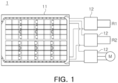
- FIG. 1 illustrates an electric vehicle driving system including a general high-voltage battery pack.
- an electric vehicle driving system 1 may include a general high-voltage battery pack 11 and various power conversion devices 12.
- the general high-voltage battery pack 11 may be formed by a series or parallel combination of a plurality of battery cells, and may not include a power conversion device.
- the general high-voltage battery pack 11 may output a single magnitude of high voltage (for example, 480 V to 806.4 V).
- the power conversion device 12 may be separated from the high-voltage battery pack 11 and provided in a space, and the high-voltage battery pack 11 and a power conversion device 12 may be connected to each other by a high-voltage cable.
- Electric vehicles may have electric loads having various functions, and a magnitude and a type of voltage required for each electric load may vary, and thus various types of power conversion devices 12 may be required.
- the electric vehicle driving system 1 including the general high-voltage battery pack 11 may be based on a single high voltage, and thus a high-voltage power conversion device 12 may need to be used.
- the electric vehicle driving system 1 may convert a high voltage output from the general high-voltage battery pack 11 into a DC low voltage to provide a driving voltage to a low-voltage load R1 or to charge a low-voltage battery. In this case, energy loss may occur in a process of converting power from a high voltage to a low voltage, which may reduce efficiency, and a voltage may need to be significantly lowered. Thus, a transformer may be additionally required.
- the electric vehicle driving system 1 may convert a voltage output from the general high-voltage battery pack 11 to provide a driving voltage to a high-voltage load R2, and may form high-voltage three-phase AC power to drive a motor M.
- an inverter operating at a high voltage, may generally use a SiC power semiconductor for high voltage switching.
- the SiC power semiconductor may have a low yield relative to high demand, which make smooth supply and demand difficult, and may be high-priced, which may increase production costs.
- the high-voltage battery pack 11 and the power conversion devices may be separated from each other, such that a space may be required for each component, and a high-voltage cable may need to be used to connect the high-voltage battery pack 11 and the power conversion devices to each other, which may occupy a significant amount of space.
- the electric vehicle driving system 1 may generate a large amount of heat due to a high-voltage output of the high-voltage battery pack 11, and a water-cooling system may be required to control heat generation, which may occupy a significant amount of space, and may be heavy.
- specifications may vary depending on a type of vehicle, and a battery system may need to be individually designed according to specifications of a type of vehicle, which may complicate a process and increase production costs.
- a battery system may be formed by a series or parallel combination of a plurality of battery modules, and each battery module may include a low-voltage battery, an inverter operating at a low voltage, and a power conversion device such as a converter or the like.
- a battery system may be formed based on a battery module, and each battery module may include a power conversion device, and thus may store/release electrical energy and perform power conversion within the battery module. Accordingly, the battery module according to an example embodiment of the present disclosure may convert DC power to AC power or convert a magnitude of battery power to output the same, as necessary.
- a high-voltage output may be formed by connecting outputs of the battery modules in series to each other, or a high-current output may be formed by connecting the outputs of the battery modules in parallel to each other, and a voltage of each battery module may be monitored and balancing-controlled.
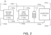
- FIG. 2 illustrates a battery module according to an example embodiment of the present disclosure.
- a battery module 10 may include a battery 110, an inverter 120, a first DC/DC converter 130, and a second DC/DC converter 140.
- the battery 110 may output a battery voltage, and may charge or discharge electrical energy.
- the battery voltage may form a basic voltage of the battery module 10 to provide an input voltage to the inverter 120, the first DC/DC converter 130, and the second DC/DC converter 140.
- the battery 110 may have a battery voltage having a magnitude, lower than that of the general high-voltage battery pack 11 described with reference to FIG. 1 . Accordingly, a power conversion element, operable at a low voltage, may be applied to the vehicle battery module 10 according to an example embodiment of the present disclosure, thereby reducing production costs.
- various magnitudes and types of voltages may be output depending on a series or parallel combination of the battery modules 10, such that a single-standard battery module 10 may be applied to types of vehicles having various specifications, thereby reducing production costs.
- the inverter 120 may convert the battery voltage into an AC module voltage and output the AC module voltage.
- the inverter 120 may include an input end and an output end. An inverter input end may be connected in parallel to a battery to receive a battery voltage, and an inverter output end may output an AC module voltage.
- the inverter output end may be referred to as an AC module output end, outputting the AC module voltage.
- the inverter 120 may be configured to supply, to the AC load, AC power according to the AC module voltage.
- the AC load may be a load such as a motor using an AC voltage as a driving voltage.
- the first DC/DC converter 130 may convert the battery voltage into a first DC module voltage lower than the battery voltage, and may output the first DC module voltage.
- the first DC/DC converter may include input ends 130a and 130b and output ends 130c and 130d.
- the input ends 130a and 130b of the first DC/DC converter may be connected in parallel to the battery to receive a battery voltage, and the output ends 130c and 130d of the first DC/DC converter may output the first DC module voltage.
- the output ends 130c and 130d of the first DC/DC converter may be referred to as first DC module output ends, outputting the first DC module voltage.
- the output ends 130c and 130d of the first DC/DC converter may be directly connected to the low-voltage load to provide the first DC module voltage.
- one output end 130d, among the output ends of the first DC/DC converter may be grounded, and the other output end 130c, among the output ends of the first DC/DC converter, may be connected to the low-voltage load to output the first DC module voltage.
- both output ends of the first DC/DC converter may be connected to both ends of the low-voltage load to output the first DC module voltage.
- the second DC/DC converter 140 may convert a battery voltage into a second DC module voltage and output the second DC module voltage.
- the second DC module voltage may be set to a value, greater than that of the first DC module voltage output from the first DC/DC converter 130.
- the second DC module voltage may be lower than or equal to the battery voltage, or may be higher than the battery voltage.
- the second DC module voltage, output from the second DC/DC converter 140 may be connected in series to a second DC module voltage output from another battery module 10 to provide power to a high-voltage load.
- the second DC module voltage, output from the second DC/DC converter 140 may not provide power to the high-voltage load as a single output, but may be connected in series to the second DC module voltage of another battery module 10 to provide power to the high-voltage load.
- a battery voltage, included in the battery module 10 may be formed as a low voltage.
- a plurality of battery modules 10 may be combined in series with each other to provide a high voltage.
- the output ends of the second DC/DC converter may be connected in series to output ends of a second DC/DC converter of another battery module to form a high voltage, thereby providing power to the high-voltage load.
- the second DC/DC converter may include input ends 140a and 140b and output ends 140c and 140d.
- the input ends 140a and 140b of the second DC/DC converter may be connected in parallel to the battery 110 to receive a battery voltage, and the output ends 140c and 140d of the second DC/DC converter may output a second DC module voltage.
- the output ends 140c and 140d of the second DC/DC converter may also be referred to as second DC module output ends, outputting the second DC module voltage.
- the output ends 140c and 140d of the second DC/DC converter may be connected in series to output ends of a second DC/DC converter included in another battery module, or may be connected to a high-voltage load.
- a specific connection structure with another battery module 10 will be described below.
- the battery 110 may be connected in parallel to the input ends 120a and 120b of the inverter, the input ends 130a and 130b of the first DC/DC converter, and the input ends 140a and 140b of the second DC/DC converter.
- FIG. 3 illustrates a battery module according to an example embodiment of the present disclosure.
- a battery module 20 may include a battery 210, an inverter 220, a first DC/DC converter 230, a second DC/DC converter 240, and a common capacitor 250.
- the common capacitor 250 may be connected in parallel to the battery 210.
- the battery module 20, illustrated in FIG. 3 may include all components of the battery module 10 illustrated in FIG. 2 , and may further include the common capacitor 250.
- one common capacitor may be shared without applying a capacitor for each inverter and each converter element. Accordingly, a volume thereof may be reduced, and a low-voltage capacitor may be applied, thereby reducing production costs.
- FIG. 4 is a diagram illustrating a connection structure between a plurality of battery modules according to an example embodiment of the present disclosure.
- a first battery module 10-1 and a second battery module 10-2 may include the same components, and may have the same structure.
- the first battery module 10-1 and the second battery module 10-2 may include batteries 110-1 and 110-2, inverters 120-1 and 120-2, first DC/DC converters 130-1 and 130-2, and second DC/DC converters 140-1 and 140-2, respectively.
- the first battery module 10-1 and the second battery module 10-2 may further include a common capacitor.
- a plurality of battery modules may be connected to each other to form a battery system, and a connection relationship between each of the plurality of battery modules, included in the battery system, may be the same as the structure illustrated in FIG. 4 .
- output ends 120-1c and 120-1d of the inverter, included in the first battery module 10-1 may be connected in series to output ends 120-2c and 120-2d of the inverter, included in the second battery module 10-2.
- the inverter 120-1, included in the first battery module, and the inverter 120-2, included in the second battery module may be connected in series to each other to output an AC module voltage having a magnitude twice as high as that of the AC module voltage.
- the AC module voltage is set to 100V
- the two inverters 120-1 and 120-2, connected in series to each other may output an AC voltage of 200V.
- a magnitude of the AC voltage may refer to a maximum value, an effective value, or an average value of the AC voltage.
- output ends 130-1c and 130-1d of the first DC/DC converter, included in the first battery module 10-1 may be connected in parallel to output ends 130-2c and 130-2d of the first DC/DC converter, included in the second battery module 10-2.
- one output end 130-1d, among the output ends of the first DC/DC converter included in the first battery module 10-1 may be grounded, and one output end 130-2d, among the output ends of the first DC/DC converter included in the second battery module 10-2, may be grounded.
- the other end 130-1c among the output ends of the first DC/DC converter included in the first battery module 10-1, may be connected in parallel to the other output end 130-2c, among the output ends of the first DC/DC converter included in the second battery module 10-2, to output a first DC module voltage.
- the output ends connected in parallel to each other, among the output ends of the first DC/DC converters may output a first DC module voltage, and may be connected to a low-voltage load using the first DC module voltage as a driving voltage to provide a voltage.
- output ends 140-1c and 140-1d of the second DC/DC converter, included in the first battery module 10-1 may be connected in series to output ends 140-2c and 140-2d of the second DC/DC converter, included in the second battery module 10-2. More specifically, one output end 140-1d, among the output ends of the second DC/DC converter included in the first battery module 10-1, may be connected to the other output end 140-2c, among the output ends of the second DC/DC converter of the second battery module 10-2.
- the second DC/DC converter 140-1 included in the first battery module
- a second DC/DC converter 140-2 included in the second battery module
- the second DC module voltage may be set to 100 V
- the two second DC/DC converters 140-1 and 140-2 may be connected in series to each other to output 200 V.
- first battery module 10-1 and the second battery module 10-2 may be connected in series to each other, the first DC/DC converters may be connected in parallel to each other, and the second DC/DC converters may be connected in series to each other.
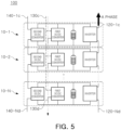
- FIG. 5 illustrates a single-phase battery system according to an example embodiment of the present disclosure.
- a single-phase battery system 100 may include a plurality of battery modules 10-1, 10-2, ..., 10-N.
- each of the plurality of battery modules 10-1, 10-2, ..., 10-N, included in the single-phase battery system 100 may be the same as the battery modules 10 and 20 illustrated in FIG. 2 or 3 .
- the plurality of battery modules 10-1, 10-2, ..., 10-N, included in the single-phase battery system 100 may have a connection structure between battery modules illustrated in FIG. 4 .
- the battery module may include first DC module output ends 130c and 130d corresponding to output ends of a first DC/DC converter, second DC module output ends 140c and 140 corresponding to output ends of a second DC/DC converter, and AC module output ends 120c and 120d corresponding to output ends of an inverter.
- the single-phase battery system 100 may include first DC system output ends 130c and 130d in which first DC module output ends, respectively included in the plurality of battery modules, are connected in parallel to each other.
- the first DC system output ends 130c and 130d may output a first DC system voltage
- the first DC system voltage may have a magnitude, the same as that of a first DC module voltage output from the output ends of the first DC/DC converter.
- the single-phase battery system 100 may include second DC system output ends 140-1c and 140-Nd in which second DC module output ends, respectively included in the plurality of battery modules, are connected in series to each other.
- the second DC system output ends 140-1c and 140-Nd may output a second DC system voltage
- the second DC system voltage may have a magnitude, integer (N) times as high as that of a second DC module voltage output from the output ends of the second DC/DC converter.
- the single-phase battery system 100 may include AC system output ends 120-1c and 120-Nd in which AC module output ends, respectively included in the plurality of battery modules, are connected in series to each other.
- the AC system output ends 120-1c and 120-Nd may output an AC system voltage, and the AC system voltage may have a magnitude, integer (N) times as high as that of an AC module voltage output from the output ends of the inverter.
- the AC system output ends may provide AC power to an AC load, and may provide an input voltage for one phase of a three-phase AC voltage.
- respective elements of the plurality of battery modules may be connected in series or parallel to each other to provide various output voltages including a first DC system voltage, a second DC system voltage, and an AC system voltage.
- an electric vehicle may include a low-voltage load R1 operating at a low voltage, a high-voltage load R2 operating at a high voltage, and an AC load, such as a motor M, operating at a high-voltage three-phase AC voltage.
- the low-voltage load may use a first DC system voltage as a driving voltage
- the high-voltage load may use a second DC system voltage as a driving voltage
- the AC load may use an AC system voltage as a driving voltage.
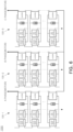
- FIG. 6 is a diagram illustrating a connection relationship between inverters in a three-phase battery system 1000 according to an example embodiment of the present disclosure.
- FIG. 7 is a diagram illustrating a connection relationship between first DC/DC converters in a three-phase battery system according to an example embodiment of the present disclosure.
- FIG. 8 is a diagram illustrating a connection relationship between second DC/DC converters in a three-phase battery system according to an example embodiment of the present disclosure.
- the three-phase battery system 1000 may include a plurality of single-phase battery systems 100-1, 100-2, and 100-3, and each of the single-phase battery systems may include a plurality of battery modules.
- the three-phase battery system 1000 may include three single-phase battery systems 100-1, 100-2, and 100-3.
- the single-phase battery systems may include an AC system output end in which inverter output ends are connected in series to each other.
- the AC system output ends, respectively included in the three single-phase battery system may output different AC voltages having the same magnitude and the same phase difference.
- each of the plurality of single-phase battery systems 100-1, 100-2, and 100-3, included in the three-phase battery system 1000 may include a first DC system output end in which a plurality of first DC /DC converters are connected in parallel to each other to output a first DC system voltage.
- the first DC system output ends, respectively included in the plurality of single-phase battery systems 100 may be connected in parallel to each other.
- 3 *N first DC/DC converters, included in the three-phase battery system 1000 may all be connected in parallel to each other to output a first AC module voltage or a first DC system voltage having a magnitude, same as that of the first DC module voltage.
- each of the plurality of single-phase battery systems 100 included in the three-phase battery system 1000 according to an example embodiment of the present disclosure, may include a second DC system output end in which a plurality of second DC/DC converters connected in series to each other to output a second DC system voltage.
- the second DC system output ends respectively included in the plurality of single-phase battery systems, may be connected in parallel to each other. That is, in the single-phase battery system 100, second DC module output ends may be connected in series to form a second DC system output end. In the three-phase battery system 1000, a plurality of second DC system output ends may be connected in parallel to each other.
- the three-phase battery system may further include a controller (not illustrated).
- the controller may individually control each battery module, and may individually control an inverter, a first DC/DC converter, and a second DC/DC converter included in each battery module. Accordingly, according to an example embodiment of the present disclosure, balancing control for each power conversion element and each battery module may be performed, thereby increasing energy efficiency.
- the controller may perform control to block only the battery module in which the issue has occurred, thereby ensuring reliability of the entire system.
- the controller may individually control each battery module. Accordingly, even when degradation occurs differently for each battery module, degradation performance of each battery module may be actively controlled.
- FIG. 9 is a diagram illustrating an inverter structure according to an example embodiment of the present disclosure.
- the inverter 120 may include a plurality of Si-metal oxide semiconductor field effect transistor (MOSFET) elements 1201, 1202, 1203, and 1204, and may have an H-bridge single-phase inverter structure.
- MOSFET Si-metal oxide semiconductor field effect transistor
- a SiC power semiconductor may be mainly applied.
- the SiC power semiconductor may have high efficiency and rapid switching speed, but may be high-priced.
- the electric vehicle system may use an insulated gate bipolar transistor (IGBT) at a low voltage.
- IGBT insulated gate bipolar transistor
- the IGBT may be relatively low-priced, but may have slow switching speed.
- the Si-MOSFET elements may have rapid switching speed, and may be relatively low-priced. However, the Si-MOSFET elements may have degraded performance at a high voltage. Accordingly, it may be difficult to apply the Si-MOSFET elements in the high-voltage electric vehicle system according to the related art.
- a battery module according to an example embodiment of the present disclosure may be driven at a low voltage, a Si-MOSFET element may be applied to an inverter. Accordingly, the inverter, included in the battery module according to an example embodiment of the present disclosure, may use a plurality of Si-MOSFET elements to reduce production costs and have a rapid switching speed. Accordingly, fuel efficiency may be improved to increase a travel distance of a vehicle. As the travel distance increases, battery capacity may be reduced to reduce production costs.
- the inverter according to an example embodiment of the present disclosure may have an H-bridge single-phase inverter structure, and may maintain stability even under a high current.
- FIG. 9 illustrates a case of forming an H-bridge circuit using four Si-MOSFETs as an example.
- the H-bridge circuit may be formed by connecting a plurality of Si-MOSFETs in parallel to each other to enable switching of a high current.
- the present disclosure provides a technology for replacing an electric vehicle driving system according to the related art, operating at a high voltage, by connecting standardized battery modules, operating at a low voltage, in series or parallel to each other.
- the battery modules may be connected in series or parallel to each other, as necessary, thereby providing various outputs.
Landscapes
- Engineering & Computer Science (AREA)
- Power Engineering (AREA)
- Transportation (AREA)
- Mechanical Engineering (AREA)
- Life Sciences & Earth Sciences (AREA)
- Sustainable Development (AREA)
- Sustainable Energy (AREA)
- Microelectronics & Electronic Packaging (AREA)
- Manufacturing & Machinery (AREA)
- Chemical & Material Sciences (AREA)
- Chemical Kinetics & Catalysis (AREA)
- Electrochemistry (AREA)
- General Chemical & Material Sciences (AREA)
- Electric Propulsion And Braking For Vehicles (AREA)
- Inverter Devices (AREA)
Applications Claiming Priority (2)
| Application Number | Priority Date | Filing Date | Title |
|---|---|---|---|
| KR20230104426 | 2023-08-09 | ||
| KR1020240093251A KR20250023268A (ko) | 2023-08-09 | 2024-07-15 | 전력변환장치를 포함하는 차량용 배터리 모듈 및 복수개의 차량용 배터리 모듈에 기반하여 구성되는 차량용 배터리 시스템 |
Publications (1)
| Publication Number | Publication Date |
|---|---|
| EP4506201A1 true EP4506201A1 (de) | 2025-02-12 |
Family
ID=92295855
Family Applications (1)
| Application Number | Title | Priority Date | Filing Date |
|---|---|---|---|
| EP24193535.2A Pending EP4506201A1 (de) | 2023-08-09 | 2024-08-08 | Fahrzeugbatteriemodul mit leistungsumwandlungsvorrichtung und auf basis von fahrzeugbatteriemodulen geformtes fahrzeugbatteriesystem |
Country Status (3)
| Country | Link |
|---|---|
| US (1) | US20250050742A1 (de) |
| EP (1) | EP4506201A1 (de) |
| CN (1) | CN119459327A (de) |
Families Citing this family (2)
| Publication number | Priority date | Publication date | Assignee | Title |
|---|---|---|---|---|
| US12466264B2 (en) * | 2021-03-01 | 2025-11-11 | Volvo Car Corporation | Battery architecture without low voltage battery |
| CN114567035A (zh) * | 2022-02-28 | 2022-05-31 | 漳州科华电气技术有限公司 | 一种电池供电装置及系统 |
Citations (2)
| Publication number | Priority date | Publication date | Assignee | Title |
|---|---|---|---|---|
| US20180043789A1 (en) * | 2015-04-30 | 2018-02-15 | Dr. Ing. H.C. F. Porsche Aktiengesellschaft | Apparatus and method for an electric power supply |
| US20220278529A1 (en) * | 2021-03-01 | 2022-09-01 | Volvo Car Corporation | Balancing in electric vehicle battery systems |
Family Cites Families (3)
| Publication number | Priority date | Publication date | Assignee | Title |
|---|---|---|---|---|
| JP3884909B2 (ja) * | 2000-12-06 | 2007-02-21 | 株式会社日立製作所 | 電気車及びその制御装置 |
| US8319471B2 (en) * | 2006-12-06 | 2012-11-27 | Solaredge, Ltd. | Battery power delivery module |
| US11101742B2 (en) * | 2020-01-03 | 2021-08-24 | Prince Sultan University | Buck-chopper and bi-directional chopper for multilevel cascaded H-bridge inverters |
-
2024
- 2024-08-08 US US18/798,329 patent/US20250050742A1/en active Pending
- 2024-08-08 EP EP24193535.2A patent/EP4506201A1/de active Pending
- 2024-08-09 CN CN202411090988.5A patent/CN119459327A/zh active Pending
Patent Citations (2)
| Publication number | Priority date | Publication date | Assignee | Title |
|---|---|---|---|---|
| US20180043789A1 (en) * | 2015-04-30 | 2018-02-15 | Dr. Ing. H.C. F. Porsche Aktiengesellschaft | Apparatus and method for an electric power supply |
| US20220278529A1 (en) * | 2021-03-01 | 2022-09-01 | Volvo Car Corporation | Balancing in electric vehicle battery systems |
Also Published As
| Publication number | Publication date |
|---|---|
| US20250050742A1 (en) | 2025-02-13 |
| CN119459327A (zh) | 2025-02-18 |
Similar Documents
| Publication | Publication Date | Title |
|---|---|---|
| US9231404B2 (en) | Energy storage device, system with energy storage device and method for driving an energy storage device | |
| US7733039B2 (en) | Electric vehicle system for charging and supplying electrical power | |
| US20250050742A1 (en) | Vehicle battery module including power conversion device and vehicle battery system formed based on vehicle battery modules | |
| US9520741B2 (en) | System for charging electrical storage device and method of making same | |
| CN105322607B (zh) | 用于提供电压的、具有串联的组变流器的装置和驱动布置 | |
| US20240343141A1 (en) | Electrical drive system for a vehicle and method for operating a corresponding electrical drive system | |
| US20140117770A1 (en) | Power converter | |
| CN119604429A (zh) | 具有电力电路装置和两个电驱动单元的车辆及其运行方法 | |
| US10618419B2 (en) | Energy storage arrangement comprising multiple energy stores | |
| US20230016726A1 (en) | Bidirectional electrical systems with high-voltage versatile battery packs | |
| CN116054576B (zh) | 用于电动车辆的能量系统 | |
| JP4329454B2 (ja) | 電気自動車システム | |
| KR20250023268A (ko) | 전력변환장치를 포함하는 차량용 배터리 모듈 및 복수개의 차량용 배터리 모듈에 기반하여 구성되는 차량용 배터리 시스템 | |
| Xia et al. | An integrated modular converter for switched reluctance motor drives in range-extended electric vehicles | |
| KR20250023319A (ko) | 전력변환장치를 포함하는 차량용 배터리 모듈 및 복수개의 차량용 배터리 모듈에 기반하여 구성되는 차량용 배터리 시스템 | |
| KR20250023320A (ko) | 전력변환장치를 포함하는 차량용 배터리 모듈 및 복수개의 차량용 배터리 모듈에 기반하여 구성되는 차량용 배터리 시스템 | |
| KR20250023322A (ko) | 전력변환장치를 포함하는 차량용 배터리 모듈 및 복수개의 차량용 배터리 모듈에 기반하여 구성되는 차량용 배터리 시스템 | |
| US20250050765A1 (en) | Vehicle and charging control method of vehicle | |
| US20250050764A1 (en) | Vehicle and charging control method of vehicle | |
| US20250083566A1 (en) | Balancing control system and balancing control method for vehicle battery module | |
| CN214900296U (zh) | 一种车载低压系统的供电结构 | |
| US11784574B2 (en) | Automotive power converter | |
| EP4545345A1 (de) | Stromversorgungssystem für ein schienenfahrzeug | |
| CN103825349A (zh) | 集成式功率变换器 | |
| KR20240124113A (ko) | 고효율 전기차 급속 충전기 |
Legal Events
| Date | Code | Title | Description |
|---|---|---|---|
| PUAI | Public reference made under article 153(3) epc to a published international application that has entered the european phase |
Free format text: ORIGINAL CODE: 0009012 |
|
| STAA | Information on the status of an ep patent application or granted ep patent |
Free format text: STATUS: THE APPLICATION HAS BEEN PUBLISHED |
|
| AK | Designated contracting states |
Kind code of ref document: A1 Designated state(s): AL AT BE BG CH CY CZ DE DK EE ES FI FR GB GR HR HU IE IS IT LI LT LU LV MC ME MK MT NL NO PL PT RO RS SE SI SK SM TR |
|
| STAA | Information on the status of an ep patent application or granted ep patent |
Free format text: STATUS: REQUEST FOR EXAMINATION WAS MADE |
|
| 17P | Request for examination filed |
Effective date: 20250520 |
|
| P01 | Opt-out of the competence of the unified patent court (upc) registered |
Free format text: CASE NUMBER: APP_23810/2025 Effective date: 20250519 |