EP4545345A1 - Stromversorgungssystem für ein schienenfahrzeug - Google Patents
Stromversorgungssystem für ein schienenfahrzeug Download PDFInfo
- Publication number
- EP4545345A1 EP4545345A1 EP23383099.1A EP23383099A EP4545345A1 EP 4545345 A1 EP4545345 A1 EP 4545345A1 EP 23383099 A EP23383099 A EP 23383099A EP 4545345 A1 EP4545345 A1 EP 4545345A1
- Authority
- EP
- European Patent Office
- Prior art keywords
- power supply
- converter
- supply system
- bus
- catenary
- Prior art date
- Legal status (The legal status is an assumption and is not a legal conclusion. Google has not performed a legal analysis and makes no representation as to the accuracy of the status listed.)
- Pending
Links
Images


Classifications
-
- B—PERFORMING OPERATIONS; TRANSPORTING
- B60—VEHICLES IN GENERAL
- B60L—PROPULSION OF ELECTRICALLY-PROPELLED VEHICLES; SUPPLYING ELECTRIC POWER FOR AUXILIARY EQUIPMENT OF ELECTRICALLY-PROPELLED VEHICLES; ELECTRODYNAMIC BRAKE SYSTEMS FOR VEHICLES IN GENERAL; MAGNETIC SUSPENSION OR LEVITATION FOR VEHICLES; MONITORING OPERATING VARIABLES OF ELECTRICALLY-PROPELLED VEHICLES; ELECTRIC SAFETY DEVICES FOR ELECTRICALLY-PROPELLED VEHICLES
- B60L50/00—Electric propulsion with power supplied within the vehicle
- B60L50/50—Electric propulsion with power supplied within the vehicle using propulsion power supplied by batteries or fuel cells
- B60L50/53—Electric propulsion with power supplied within the vehicle using propulsion power supplied by batteries or fuel cells in combination with an external power supply, e.g. from overhead contact lines
-
- B—PERFORMING OPERATIONS; TRANSPORTING
- B60—VEHICLES IN GENERAL
- B60L—PROPULSION OF ELECTRICALLY-PROPELLED VEHICLES; SUPPLYING ELECTRIC POWER FOR AUXILIARY EQUIPMENT OF ELECTRICALLY-PROPELLED VEHICLES; ELECTRODYNAMIC BRAKE SYSTEMS FOR VEHICLES IN GENERAL; MAGNETIC SUSPENSION OR LEVITATION FOR VEHICLES; MONITORING OPERATING VARIABLES OF ELECTRICALLY-PROPELLED VEHICLES; ELECTRIC SAFETY DEVICES FOR ELECTRICALLY-PROPELLED VEHICLES
- B60L3/00—Electric devices on electrically-propelled vehicles for safety purposes; Monitoring operating variables, e.g. speed, deceleration or energy consumption
- B60L3/0023—Detecting, eliminating, remedying or compensating for drive train abnormalities, e.g. failures within the drive train
- B60L3/003—Detecting, eliminating, remedying or compensating for drive train abnormalities, e.g. failures within the drive train relating to inverters
-
- B—PERFORMING OPERATIONS; TRANSPORTING
- B60—VEHICLES IN GENERAL
- B60L—PROPULSION OF ELECTRICALLY-PROPELLED VEHICLES; SUPPLYING ELECTRIC POWER FOR AUXILIARY EQUIPMENT OF ELECTRICALLY-PROPELLED VEHICLES; ELECTRODYNAMIC BRAKE SYSTEMS FOR VEHICLES IN GENERAL; MAGNETIC SUSPENSION OR LEVITATION FOR VEHICLES; MONITORING OPERATING VARIABLES OF ELECTRICALLY-PROPELLED VEHICLES; ELECTRIC SAFETY DEVICES FOR ELECTRICALLY-PROPELLED VEHICLES
- B60L50/00—Electric propulsion with power supplied within the vehicle
- B60L50/50—Electric propulsion with power supplied within the vehicle using propulsion power supplied by batteries or fuel cells
- B60L50/51—Electric propulsion with power supplied within the vehicle using propulsion power supplied by batteries or fuel cells characterised by AC-motors
-
- B—PERFORMING OPERATIONS; TRANSPORTING
- B60—VEHICLES IN GENERAL
- B60L—PROPULSION OF ELECTRICALLY-PROPELLED VEHICLES; SUPPLYING ELECTRIC POWER FOR AUXILIARY EQUIPMENT OF ELECTRICALLY-PROPELLED VEHICLES; ELECTRODYNAMIC BRAKE SYSTEMS FOR VEHICLES IN GENERAL; MAGNETIC SUSPENSION OR LEVITATION FOR VEHICLES; MONITORING OPERATING VARIABLES OF ELECTRICALLY-PROPELLED VEHICLES; ELECTRIC SAFETY DEVICES FOR ELECTRICALLY-PROPELLED VEHICLES
- B60L53/00—Methods of charging batteries, specially adapted for electric vehicles; Charging stations or on-board charging equipment therefor; Exchange of energy storage elements in electric vehicles
- B60L53/20—Methods of charging batteries, specially adapted for electric vehicles; Charging stations or on-board charging equipment therefor; Exchange of energy storage elements in electric vehicles characterised by converters located in the vehicle
-
- B—PERFORMING OPERATIONS; TRANSPORTING
- B60—VEHICLES IN GENERAL
- B60L—PROPULSION OF ELECTRICALLY-PROPELLED VEHICLES; SUPPLYING ELECTRIC POWER FOR AUXILIARY EQUIPMENT OF ELECTRICALLY-PROPELLED VEHICLES; ELECTRODYNAMIC BRAKE SYSTEMS FOR VEHICLES IN GENERAL; MAGNETIC SUSPENSION OR LEVITATION FOR VEHICLES; MONITORING OPERATING VARIABLES OF ELECTRICALLY-PROPELLED VEHICLES; ELECTRIC SAFETY DEVICES FOR ELECTRICALLY-PROPELLED VEHICLES
- B60L9/00—Electric propulsion with power supply external to the vehicle
- B60L9/02—Electric propulsion with power supply external to the vehicle using DC motors
- B60L9/04—Electric propulsion with power supply external to the vehicle using DC motors fed from DC supply lines
-
- B—PERFORMING OPERATIONS; TRANSPORTING
- B60—VEHICLES IN GENERAL
- B60L—PROPULSION OF ELECTRICALLY-PROPELLED VEHICLES; SUPPLYING ELECTRIC POWER FOR AUXILIARY EQUIPMENT OF ELECTRICALLY-PROPELLED VEHICLES; ELECTRODYNAMIC BRAKE SYSTEMS FOR VEHICLES IN GENERAL; MAGNETIC SUSPENSION OR LEVITATION FOR VEHICLES; MONITORING OPERATING VARIABLES OF ELECTRICALLY-PROPELLED VEHICLES; ELECTRIC SAFETY DEVICES FOR ELECTRICALLY-PROPELLED VEHICLES
- B60L2200/00—Type of vehicles
- B60L2200/26—Rail vehicles
-
- B—PERFORMING OPERATIONS; TRANSPORTING
- B60—VEHICLES IN GENERAL
- B60L—PROPULSION OF ELECTRICALLY-PROPELLED VEHICLES; SUPPLYING ELECTRIC POWER FOR AUXILIARY EQUIPMENT OF ELECTRICALLY-PROPELLED VEHICLES; ELECTRODYNAMIC BRAKE SYSTEMS FOR VEHICLES IN GENERAL; MAGNETIC SUSPENSION OR LEVITATION FOR VEHICLES; MONITORING OPERATING VARIABLES OF ELECTRICALLY-PROPELLED VEHICLES; ELECTRIC SAFETY DEVICES FOR ELECTRICALLY-PROPELLED VEHICLES
- B60L2210/00—Converter types
- B60L2210/10—DC to DC converters
- B60L2210/14—Boost converters
-
- B—PERFORMING OPERATIONS; TRANSPORTING
- B60—VEHICLES IN GENERAL
- B60L—PROPULSION OF ELECTRICALLY-PROPELLED VEHICLES; SUPPLYING ELECTRIC POWER FOR AUXILIARY EQUIPMENT OF ELECTRICALLY-PROPELLED VEHICLES; ELECTRODYNAMIC BRAKE SYSTEMS FOR VEHICLES IN GENERAL; MAGNETIC SUSPENSION OR LEVITATION FOR VEHICLES; MONITORING OPERATING VARIABLES OF ELECTRICALLY-PROPELLED VEHICLES; ELECTRIC SAFETY DEVICES FOR ELECTRICALLY-PROPELLED VEHICLES
- B60L2210/00—Converter types
- B60L2210/20—AC to AC converters
-
- B—PERFORMING OPERATIONS; TRANSPORTING
- B60—VEHICLES IN GENERAL
- B60L—PROPULSION OF ELECTRICALLY-PROPELLED VEHICLES; SUPPLYING ELECTRIC POWER FOR AUXILIARY EQUIPMENT OF ELECTRICALLY-PROPELLED VEHICLES; ELECTRODYNAMIC BRAKE SYSTEMS FOR VEHICLES IN GENERAL; MAGNETIC SUSPENSION OR LEVITATION FOR VEHICLES; MONITORING OPERATING VARIABLES OF ELECTRICALLY-PROPELLED VEHICLES; ELECTRIC SAFETY DEVICES FOR ELECTRICALLY-PROPELLED VEHICLES
- B60L2210/00—Converter types
- B60L2210/40—DC to AC converters
Definitions
- the present invention relates to a power supply system for a railway vehicle, in particular for a railway vehicle that uses at least one electric battery to be driven.
- railway vehicles that dispense with fossil fuel power sources, with electric batteries also being used as the main power source for the traction motors of these vehicles.
- Such railway vehicles are known as BEMUs (Battery Electric Multiple Units).
- BEMUs Battery Electric Multiple Units
- these vehicles are designed to be connected to a catenary, so that the traction motors can be powered both by energy obtained from the catenary and from the electric batteries.
- These electric batteries are rechargeable and can be recharged for example with energy from the catenary or even with energy left over from the braking of the vehicles.
- EP3878680A2 discloses a BEMU with a power supply system comprising a connection for connecting to an AC catenary to provide AC electrical power from the AC catenary to the railway vehicle; an AC-DC converter for converting the AC electrical power to DC electrical power for a DC bus of the power supply system; and an inverter for converting the DC electrical power from the DC bus to AC electrical power for powering at least one traction motor of the vehicle.
- the power system further comprises a rechargeable electric battery connected to the DC bus.
- the object of the invention is to provide a power supply system for a railway vehicle, as defined in the claims.
- the power supply system comprises a connection point for being connected to a catenary; a DC bus; a traction inverter connected to the DC bus and configured to convert DC electrical power from the DC bus to AC three-phase power to electrically supply at least one traction motor of the railway vehicle; and a traction battery connected to the DC bus.
- the power supply system is configured to be connected to a DC catenary that provides a DC voltage with a determined maximum value through the connection point.
- the power supply system further comprises a DC-DC converter connected between the connection point and the DC bus, which is configured to boost the DC voltage from the catenary to a value higher than the value of the DC voltage provided by the catenary.
- a DC catenary is adapted to provide a given nominal DC voltage fluctuating between a given minimum and a given maximum permissible value, in normal operating conditions, but this DC voltage may have voltage peaks exceeding the given maximum value (an effect known as overvoltage). Due to the ability of the DC-DC converter to boost the voltage it receives, when there is an overvoltage in the catenary, the DC-DC converter is prepared (configured) to absorb the overvoltage and the power supply system does not require specific protection components to be protected against said overvoltage, resulting in a smaller and therefore lighter power supply system.
- the higher voltage provided by the DC-DC converter is also positive when interacting with the battery, as it gives better control over the battery charging current.
- the starting voltage is higher than in the state of the art and this allows for a lower charging current for the same battery charging power, with less influence on the negative performance of the battery.
- a railway vehicle 200 when a railway vehicle 200 is connected to a DC catenary 100 through the connection point 2 of the power supply system 1, said railway vehicle 200 can be supplied with electrical power from said catenary 100 to generate the traction for its movement, said power supply system 1 being able to receive a voltage from said catenary 100 that fluctuates between a maximum and a minimum value in accordance with the regulations corresponding to the territory where said catenary 100 is installed (and through which said railway vehicle 200 circulates).
- the power supply system 1 further comprises at least one DC bus 4 associated with the connection point 2; a traction inverter 5 connected to the DC bus 4 and configured to convert a DC electrical power from said DC bus 4 into AC three-phase power and to connect to at least one traction motor M of the railway vehicle 200 to supply said traction motor M, said traction motor M being in charge of driving the railway vehicle 200 (driving at least one wheel 201 of said railway vehicle 200).
- the power supply system 1 thus comprises a connection 9 adapted to be connected to a traction motor M, the traction inverter 5 being connected to the traction motor M via said connection 9.
- the power supply system 1 further comprises a traction battery 6 connected to the DC bus 4. Connecting the battery 6 directly to the DC bus 4 allows for higher energy efficiency in the power supply system 1, since compared to some prior art solutions in which a battery is connected to the DC bus via a DC-DC converter, fewer conversion stages are required (only that of the traction inverter 5).
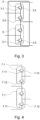
- the power supply system 1 comprises a traction inverter 5 and a DC bus 4 associated to the connection point 2 for each traction motor M, as depicted in Figure 2 , and preferably, in addition, the power supply system 1 comprises a respective battery 6 connected to each of the DC buses 4.
- the catenary 100 Under normal circumstances, when there is no anomaly in the catenary 100, the catenary 100 provides a nominal voltage whose value may fluctuate between a determined minimum value and a determined maximum value, as described above. However, the catenary 100 may provide a voltage with a value higher than said maximum value in abnormal situations. This overvoltage can damage at least the power supply system which is connected to the catenary 100, so that known power supply systems comprise specific protection components to absorb the excess electrical power reaching the said power supply system caused by the overvoltage of the catenary 100.
- the proposed power supply system 1 further comprises a DC - DC converter 3 which is connected between the connection point 2 and the DC bus 4.
- the power supply system 1 comprises one DC - DC converter 3 per traction motor M, as depicted in Figure 2 .
- the DC-DC converter 3 is designed as a boost converter, to boost the DC voltage coming from the catenary 100, such that, in use, at the output of the DC-DC converter 3 there is a DC voltage with a higher value than the value of the DC voltage provided by the catenary 100.
Landscapes
- Engineering & Computer Science (AREA)
- Power Engineering (AREA)
- Transportation (AREA)
- Mechanical Engineering (AREA)
- Life Sciences & Earth Sciences (AREA)
- Sustainable Development (AREA)
- Sustainable Energy (AREA)
- Electric Propulsion And Braking For Vehicles (AREA)
Priority Applications (1)
| Application Number | Priority Date | Filing Date | Title |
|---|---|---|---|
| EP23383099.1A EP4545345A1 (de) | 2023-10-27 | 2023-10-27 | Stromversorgungssystem für ein schienenfahrzeug |
Applications Claiming Priority (1)
| Application Number | Priority Date | Filing Date | Title |
|---|---|---|---|
| EP23383099.1A EP4545345A1 (de) | 2023-10-27 | 2023-10-27 | Stromversorgungssystem für ein schienenfahrzeug |
Publications (1)
| Publication Number | Publication Date |
|---|---|
| EP4545345A1 true EP4545345A1 (de) | 2025-04-30 |
Family
ID=88757593
Family Applications (1)
| Application Number | Title | Priority Date | Filing Date |
|---|---|---|---|
| EP23383099.1A Pending EP4545345A1 (de) | 2023-10-27 | 2023-10-27 | Stromversorgungssystem für ein schienenfahrzeug |
Country Status (1)
| Country | Link |
|---|---|
| EP (1) | EP4545345A1 (de) |
Citations (3)
| Publication number | Priority date | Publication date | Assignee | Title |
|---|---|---|---|---|
| JP2009072003A (ja) * | 2007-09-14 | 2009-04-02 | Kawasaki Heavy Ind Ltd | 電気鉄道システム |
| EP2586646B1 (de) * | 2011-10-28 | 2019-12-04 | Bombardier Transportation GmbH | Elektrische Energieversorgungsanordnung für Antriebseinrichtungen, zum Betreiben eines Schienenfahrzeugs an elektrischen Versorgungsnetzen |
| EP3878680A2 (de) | 2020-03-13 | 2021-09-15 | Hitachi Rail Limited | Antriebssystem für ein schienenfahrzeug |
-
2023
- 2023-10-27 EP EP23383099.1A patent/EP4545345A1/de active Pending
Patent Citations (3)
| Publication number | Priority date | Publication date | Assignee | Title |
|---|---|---|---|---|
| JP2009072003A (ja) * | 2007-09-14 | 2009-04-02 | Kawasaki Heavy Ind Ltd | 電気鉄道システム |
| EP2586646B1 (de) * | 2011-10-28 | 2019-12-04 | Bombardier Transportation GmbH | Elektrische Energieversorgungsanordnung für Antriebseinrichtungen, zum Betreiben eines Schienenfahrzeugs an elektrischen Versorgungsnetzen |
| EP3878680A2 (de) | 2020-03-13 | 2021-09-15 | Hitachi Rail Limited | Antriebssystem für ein schienenfahrzeug |
Similar Documents
| Publication | Publication Date | Title |
|---|---|---|
| US9018792B2 (en) | Arrangement for operating consumers in a rail vehicle with electrical energy, selectively from an energy supply network or from a motor-generator combination | |
| EP2872359B1 (de) | Energieverwaltungssystem für schienengebundene fahrzeuge | |
| RU2422299C1 (ru) | Система электроснабжения электропоезда с асинхронным тяговым приводом | |
| EP2695763B1 (de) | Traktionsstromrichter für Mehrsystem-Schienenfahrzeug | |
| US11515808B2 (en) | Electrical system comprising at least two modules | |
| US11834033B2 (en) | Regenerative braking system and electrically-driven work vehicle using regenerative braking system | |
| CN212579619U (zh) | 用于轨道车辆的能量供应装置和轨道车辆 | |
| JP2017225280A (ja) | 電力変換システム | |
| KR101957469B1 (ko) | 다권선 고주파 변압기를 이용한 철도차량용 반도체 변압기 | |
| JP2017225279A (ja) | 電力変換システム | |
| EP2452848B1 (de) | Elektrische fahrzeugsteuerungsvorrichtung | |
| CN111969684B (zh) | 电动车充电电路及电动车 | |
| CN119604429A (zh) | 具有电力电路装置和两个电驱动单元的车辆及其运行方法 | |
| EP4506201A1 (de) | Fahrzeugbatteriemodul mit leistungsumwandlungsvorrichtung und auf basis von fahrzeugbatteriemodulen geformtes fahrzeugbatteriesystem | |
| US20250074201A1 (en) | Power supply for a rail vehicle, having a traction battery | |
| CN114026765B (zh) | 车辆车载电网 | |
| EP2629413A1 (de) | Stromversorgung eines schienengebundenen Elektrofahrzeugs mittels modularer Multilevelumrichter | |
| JP6786268B2 (ja) | 蓄電システム | |
| CN109412469B (zh) | 牵引变流系统主电路、控制方法及其系统 | |
| RU2623643C1 (ru) | Способ регулирования напряжения системы газовая турбина - генератор для обеспечения питания вспомогательных электрических приводов транспортного средства | |
| JP7821751B2 (ja) | 鉄道車両用の駆動システムおよび駆動方法 | |
| CN119636435B (zh) | 一种集成主辅供功能的机车变流系统及方法 | |
| EP4467383A1 (de) | Mehrstrom-energiesystem für ein schienenfahrzeug | |
| KR102338125B1 (ko) | 육상 ac 전력과 연계 가능한 선박용 dc 기반 전력 공급 시스템 | |
| US20260091696A1 (en) | Control schemes for vehicle-to-load electrical power |
Legal Events
| Date | Code | Title | Description |
|---|---|---|---|
| PUAI | Public reference made under article 153(3) epc to a published international application that has entered the european phase |
Free format text: ORIGINAL CODE: 0009012 |
|
| STAA | Information on the status of an ep patent application or granted ep patent |
Free format text: STATUS: REQUEST FOR EXAMINATION WAS MADE |
|
| 17P | Request for examination filed |
Effective date: 20240930 |
|
| AK | Designated contracting states |
Kind code of ref document: A1 Designated state(s): AL AT BE BG CH CY CZ DE DK EE ES FI FR GB GR HR HU IE IS IT LI LT LU LV MC ME MK MT NL NO PL PT RO RS SE SI SK SM TR |