EP4506204A2 - Leistungsumwandlungsvorrichtung und ladevorrichtung - Google Patents
Leistungsumwandlungsvorrichtung und ladevorrichtung Download PDFInfo
- Publication number
- EP4506204A2 EP4506204A2 EP24184467.9A EP24184467A EP4506204A2 EP 4506204 A2 EP4506204 A2 EP 4506204A2 EP 24184467 A EP24184467 A EP 24184467A EP 4506204 A2 EP4506204 A2 EP 4506204A2
- Authority
- EP
- European Patent Office
- Prior art keywords
- power conversion
- circulating current
- timer
- conversion apparatus
- primary
- Prior art date
- Legal status (The legal status is an assumption and is not a legal conclusion. Google has not performed a legal analysis and makes no representation as to the accuracy of the status listed.)
- Pending
Links
Images




Classifications
-
- B—PERFORMING OPERATIONS; TRANSPORTING
- B60—VEHICLES IN GENERAL
- B60L—PROPULSION OF ELECTRICALLY-PROPELLED VEHICLES; SUPPLYING ELECTRIC POWER FOR AUXILIARY EQUIPMENT OF ELECTRICALLY-PROPELLED VEHICLES; ELECTRODYNAMIC BRAKE SYSTEMS FOR VEHICLES IN GENERAL; MAGNETIC SUSPENSION OR LEVITATION FOR VEHICLES; MONITORING OPERATING VARIABLES OF ELECTRICALLY-PROPELLED VEHICLES; ELECTRIC SAFETY DEVICES FOR ELECTRICALLY-PROPELLED VEHICLES
- B60L53/00—Methods of charging batteries, specially adapted for electric vehicles; Charging stations or on-board charging equipment therefor; Exchange of energy storage elements in electric vehicles
- B60L53/10—Methods of charging batteries, specially adapted for electric vehicles; Charging stations or on-board charging equipment therefor; Exchange of energy storage elements in electric vehicles characterised by the energy transfer between the charging station and the vehicle
-
- H—ELECTRICITY
- H02—GENERATION; CONVERSION OR DISTRIBUTION OF ELECTRIC POWER
- H02M—APPARATUS FOR CONVERSION BETWEEN AC AND AC, BETWEEN AC AND DC, OR BETWEEN DC AND DC, AND FOR USE WITH MAINS OR SIMILAR POWER SUPPLY SYSTEMS; CONVERSION OF DC OR AC INPUT POWER INTO SURGE OUTPUT POWER; CONTROL OR REGULATION THEREOF
- H02M1/00—Details of apparatus for conversion
- H02M1/0003—Details of control, feedback or regulation circuits
- H02M1/0041—Control circuits in which a clock signal is selectively enabled or disabled
-
- H—ELECTRICITY
- H02—GENERATION; CONVERSION OR DISTRIBUTION OF ELECTRIC POWER
- H02M—APPARATUS FOR CONVERSION BETWEEN AC AND AC, BETWEEN AC AND DC, OR BETWEEN DC AND DC, AND FOR USE WITH MAINS OR SIMILAR POWER SUPPLY SYSTEMS; CONVERSION OF DC OR AC INPUT POWER INTO SURGE OUTPUT POWER; CONTROL OR REGULATION THEREOF
- H02M1/00—Details of apparatus for conversion
- H02M1/0003—Details of control, feedback or regulation circuits
- H02M1/0038—Circuits or arrangements for suppressing, e.g. by masking incorrect turn-on or turn-off signals, e.g. due to current spikes in current mode control
-
- B—PERFORMING OPERATIONS; TRANSPORTING
- B60—VEHICLES IN GENERAL
- B60L—PROPULSION OF ELECTRICALLY-PROPELLED VEHICLES; SUPPLYING ELECTRIC POWER FOR AUXILIARY EQUIPMENT OF ELECTRICALLY-PROPELLED VEHICLES; ELECTRODYNAMIC BRAKE SYSTEMS FOR VEHICLES IN GENERAL; MAGNETIC SUSPENSION OR LEVITATION FOR VEHICLES; MONITORING OPERATING VARIABLES OF ELECTRICALLY-PROPELLED VEHICLES; ELECTRIC SAFETY DEVICES FOR ELECTRICALLY-PROPELLED VEHICLES
- B60L53/00—Methods of charging batteries, specially adapted for electric vehicles; Charging stations or on-board charging equipment therefor; Exchange of energy storage elements in electric vehicles
- B60L53/20—Methods of charging batteries, specially adapted for electric vehicles; Charging stations or on-board charging equipment therefor; Exchange of energy storage elements in electric vehicles characterised by converters located in the vehicle
-
- B—PERFORMING OPERATIONS; TRANSPORTING
- B60—VEHICLES IN GENERAL
- B60L—PROPULSION OF ELECTRICALLY-PROPELLED VEHICLES; SUPPLYING ELECTRIC POWER FOR AUXILIARY EQUIPMENT OF ELECTRICALLY-PROPELLED VEHICLES; ELECTRODYNAMIC BRAKE SYSTEMS FOR VEHICLES IN GENERAL; MAGNETIC SUSPENSION OR LEVITATION FOR VEHICLES; MONITORING OPERATING VARIABLES OF ELECTRICALLY-PROPELLED VEHICLES; ELECTRIC SAFETY DEVICES FOR ELECTRICALLY-PROPELLED VEHICLES
- B60L53/00—Methods of charging batteries, specially adapted for electric vehicles; Charging stations or on-board charging equipment therefor; Exchange of energy storage elements in electric vehicles
- B60L53/20—Methods of charging batteries, specially adapted for electric vehicles; Charging stations or on-board charging equipment therefor; Exchange of energy storage elements in electric vehicles characterised by converters located in the vehicle
- B60L53/22—Constructional details or arrangements of charging converters specially adapted for charging electric vehicles
-
- H—ELECTRICITY
- H02—GENERATION; CONVERSION OR DISTRIBUTION OF ELECTRIC POWER
- H02J—ELECTRIC POWER NETWORKS; CIRCUIT ARRANGEMENTS OR SYSTEMS FOR SUPPLYING OR DISTRIBUTING ELECTRIC POWER; SYSTEMS FOR STORING ELECTRIC ENERGY
- H02J1/00—Circuit arrangements for DC mains or DC distribution networks
- H02J1/10—Parallel operation of DC sources
- H02J1/102—Parallel operation of DC sources being switching converters
-
- H—ELECTRICITY
- H02—GENERATION; CONVERSION OR DISTRIBUTION OF ELECTRIC POWER
- H02J—ELECTRIC POWER NETWORKS; CIRCUIT ARRANGEMENTS OR SYSTEMS FOR SUPPLYING OR DISTRIBUTING ELECTRIC POWER; SYSTEMS FOR STORING ELECTRIC ENERGY
- H02J3/00—Circuit arrangements for AC mains or AC distribution networks
- H02J3/38—Arrangements for feeding a single network from two or more generators or sources in parallel; Arrangements for feeding already energised networks from additional generators or sources in parallel
- H02J3/46—Controlling the sharing of generated power between the generators, sources or networks
-
- H—ELECTRICITY
- H02—GENERATION; CONVERSION OR DISTRIBUTION OF ELECTRIC POWER
- H02J—ELECTRIC POWER NETWORKS; CIRCUIT ARRANGEMENTS OR SYSTEMS FOR SUPPLYING OR DISTRIBUTING ELECTRIC POWER; SYSTEMS FOR STORING ELECTRIC ENERGY
- H02J7/00—Circuit arrangements for charging or discharging batteries or for supplying loads from batteries
- H02J7/40—Circuit arrangements for charging or discharging batteries or for supplying loads from batteries characterised by the exchange of charge or discharge related data
- H02J7/44—Circuit arrangements for charging or discharging batteries or for supplying loads from batteries characterised by the exchange of charge or discharge related data between battery management systems and power sources
-
- H—ELECTRICITY
- H02—GENERATION; CONVERSION OR DISTRIBUTION OF ELECTRIC POWER
- H02J—ELECTRIC POWER NETWORKS; CIRCUIT ARRANGEMENTS OR SYSTEMS FOR SUPPLYING OR DISTRIBUTING ELECTRIC POWER; SYSTEMS FOR STORING ELECTRIC ENERGY
- H02J7/00—Circuit arrangements for charging or discharging batteries or for supplying loads from batteries
- H02J7/50—Circuit arrangements for charging or discharging batteries or for supplying loads from batteries acting upon multiple batteries simultaneously or sequentially
-
- H—ELECTRICITY
- H02—GENERATION; CONVERSION OR DISTRIBUTION OF ELECTRIC POWER
- H02M—APPARATUS FOR CONVERSION BETWEEN AC AND AC, BETWEEN AC AND DC, OR BETWEEN DC AND DC, AND FOR USE WITH MAINS OR SIMILAR POWER SUPPLY SYSTEMS; CONVERSION OF DC OR AC INPUT POWER INTO SURGE OUTPUT POWER; CONTROL OR REGULATION THEREOF
- H02M1/00—Details of apparatus for conversion
- H02M1/0003—Details of control, feedback or regulation circuits
- H02M1/0009—Devices or circuits for detecting current in a converter
-
- H—ELECTRICITY
- H02—GENERATION; CONVERSION OR DISTRIBUTION OF ELECTRIC POWER
- H02M—APPARATUS FOR CONVERSION BETWEEN AC AND AC, BETWEEN AC AND DC, OR BETWEEN DC AND DC, AND FOR USE WITH MAINS OR SIMILAR POWER SUPPLY SYSTEMS; CONVERSION OF DC OR AC INPUT POWER INTO SURGE OUTPUT POWER; CONTROL OR REGULATION THEREOF
- H02M1/00—Details of apparatus for conversion
- H02M1/0043—Converters switched with a phase shift, i.e. interleaved
-
- H—ELECTRICITY
- H02—GENERATION; CONVERSION OR DISTRIBUTION OF ELECTRIC POWER
- H02M—APPARATUS FOR CONVERSION BETWEEN AC AND AC, BETWEEN AC AND DC, OR BETWEEN DC AND DC, AND FOR USE WITH MAINS OR SIMILAR POWER SUPPLY SYSTEMS; CONVERSION OF DC OR AC INPUT POWER INTO SURGE OUTPUT POWER; CONTROL OR REGULATION THEREOF
- H02M1/00—Details of apparatus for conversion
- H02M1/0048—Circuits or arrangements for reducing losses
-
- H—ELECTRICITY
- H02—GENERATION; CONVERSION OR DISTRIBUTION OF ELECTRIC POWER
- H02M—APPARATUS FOR CONVERSION BETWEEN AC AND AC, BETWEEN AC AND DC, OR BETWEEN DC AND DC, AND FOR USE WITH MAINS OR SIMILAR POWER SUPPLY SYSTEMS; CONVERSION OF DC OR AC INPUT POWER INTO SURGE OUTPUT POWER; CONTROL OR REGULATION THEREOF
- H02M1/00—Details of apparatus for conversion
- H02M1/08—Circuits specially adapted for the generation of control voltages for semiconductor devices incorporated in static converters
- H02M1/088—Circuits specially adapted for the generation of control voltages for semiconductor devices incorporated in static converters for the simultaneous control of series or parallel connected semiconductor devices
-
- H—ELECTRICITY
- H02—GENERATION; CONVERSION OR DISTRIBUTION OF ELECTRIC POWER
- H02M—APPARATUS FOR CONVERSION BETWEEN AC AND AC, BETWEEN AC AND DC, OR BETWEEN DC AND DC, AND FOR USE WITH MAINS OR SIMILAR POWER SUPPLY SYSTEMS; CONVERSION OF DC OR AC INPUT POWER INTO SURGE OUTPUT POWER; CONTROL OR REGULATION THEREOF
- H02M1/00—Details of apparatus for conversion
- H02M1/32—Means for protecting converters other than automatic disconnection
-
- H—ELECTRICITY
- H02—GENERATION; CONVERSION OR DISTRIBUTION OF ELECTRIC POWER
- H02M—APPARATUS FOR CONVERSION BETWEEN AC AND AC, BETWEEN AC AND DC, OR BETWEEN DC AND DC, AND FOR USE WITH MAINS OR SIMILAR POWER SUPPLY SYSTEMS; CONVERSION OF DC OR AC INPUT POWER INTO SURGE OUTPUT POWER; CONTROL OR REGULATION THEREOF
- H02M1/00—Details of apparatus for conversion
- H02M1/42—Circuits or arrangements for compensating for or adjusting power factor in converters or inverters
- H02M1/4208—Arrangements for improving power factor of AC input
- H02M1/4216—Arrangements for improving power factor of AC input operating from a three-phase input voltage
-
- H—ELECTRICITY
- H02—GENERATION; CONVERSION OR DISTRIBUTION OF ELECTRIC POWER
- H02M—APPARATUS FOR CONVERSION BETWEEN AC AND AC, BETWEEN AC AND DC, OR BETWEEN DC AND DC, AND FOR USE WITH MAINS OR SIMILAR POWER SUPPLY SYSTEMS; CONVERSION OF DC OR AC INPUT POWER INTO SURGE OUTPUT POWER; CONTROL OR REGULATION THEREOF
- H02M1/00—Details of apparatus for conversion
- H02M1/42—Circuits or arrangements for compensating for or adjusting power factor in converters or inverters
- H02M1/4208—Arrangements for improving power factor of AC input
- H02M1/4233—Arrangements for improving power factor of AC input using a bridge converter comprising active switches
-
- H—ELECTRICITY
- H02—GENERATION; CONVERSION OR DISTRIBUTION OF ELECTRIC POWER
- H02M—APPARATUS FOR CONVERSION BETWEEN AC AND AC, BETWEEN AC AND DC, OR BETWEEN DC AND DC, AND FOR USE WITH MAINS OR SIMILAR POWER SUPPLY SYSTEMS; CONVERSION OF DC OR AC INPUT POWER INTO SURGE OUTPUT POWER; CONTROL OR REGULATION THEREOF
- H02M7/00—Conversion of AC power input into DC power output; Conversion of DC power input into AC power output
- H02M7/02—Conversion of AC power input into DC power output without possibility of reversal
- H02M7/04—Conversion of AC power input into DC power output without possibility of reversal by static converters
- H02M7/12—Conversion of AC power input into DC power output without possibility of reversal by static converters using discharge tubes with control electrode or semiconductor devices with control electrode
- H02M7/21—Conversion of AC power input into DC power output without possibility of reversal by static converters using discharge tubes with control electrode or semiconductor devices with control electrode using devices of a triode or transistor type requiring continuous application of a control signal
- H02M7/217—Conversion of AC power input into DC power output without possibility of reversal by static converters using discharge tubes with control electrode or semiconductor devices with control electrode using devices of a triode or transistor type requiring continuous application of a control signal using semiconductor devices only
- H02M7/219—Conversion of AC power input into DC power output without possibility of reversal by static converters using discharge tubes with control electrode or semiconductor devices with control electrode using devices of a triode or transistor type requiring continuous application of a control signal using semiconductor devices only in a bridge configuration
-
- H—ELECTRICITY
- H02—GENERATION; CONVERSION OR DISTRIBUTION OF ELECTRIC POWER
- H02M—APPARATUS FOR CONVERSION BETWEEN AC AND AC, BETWEEN AC AND DC, OR BETWEEN DC AND DC, AND FOR USE WITH MAINS OR SIMILAR POWER SUPPLY SYSTEMS; CONVERSION OF DC OR AC INPUT POWER INTO SURGE OUTPUT POWER; CONTROL OR REGULATION THEREOF
- H02M7/00—Conversion of AC power input into DC power output; Conversion of DC power input into AC power output
- H02M7/02—Conversion of AC power input into DC power output without possibility of reversal
- H02M7/04—Conversion of AC power input into DC power output without possibility of reversal by static converters
- H02M7/12—Conversion of AC power input into DC power output without possibility of reversal by static converters using discharge tubes with control electrode or semiconductor devices with control electrode
- H02M7/21—Conversion of AC power input into DC power output without possibility of reversal by static converters using discharge tubes with control electrode or semiconductor devices with control electrode using devices of a triode or transistor type requiring continuous application of a control signal
- H02M7/217—Conversion of AC power input into DC power output without possibility of reversal by static converters using discharge tubes with control electrode or semiconductor devices with control electrode using devices of a triode or transistor type requiring continuous application of a control signal using semiconductor devices only
- H02M7/23—Conversion of AC power input into DC power output without possibility of reversal by static converters using discharge tubes with control electrode or semiconductor devices with control electrode using devices of a triode or transistor type requiring continuous application of a control signal using semiconductor devices only arranged for operation in parallel
-
- H—ELECTRICITY
- H04—ELECTRIC COMMUNICATION TECHNIQUE
- H04L—TRANSMISSION OF DIGITAL INFORMATION, e.g. TELEGRAPHIC COMMUNICATION
- H04L12/00—Data switching networks
- H04L12/28—Data switching networks characterised by path configuration, e.g. LAN [Local Area Networks] or WAN [Wide Area Networks]
- H04L12/40—Bus networks
- H04L12/40006—Architecture of a communication node
- H04L12/40013—Details regarding a bus controller
-
- B—PERFORMING OPERATIONS; TRANSPORTING
- B60—VEHICLES IN GENERAL
- B60L—PROPULSION OF ELECTRICALLY-PROPELLED VEHICLES; SUPPLYING ELECTRIC POWER FOR AUXILIARY EQUIPMENT OF ELECTRICALLY-PROPELLED VEHICLES; ELECTRODYNAMIC BRAKE SYSTEMS FOR VEHICLES IN GENERAL; MAGNETIC SUSPENSION OR LEVITATION FOR VEHICLES; MONITORING OPERATING VARIABLES OF ELECTRICALLY-PROPELLED VEHICLES; ELECTRIC SAFETY DEVICES FOR ELECTRICALLY-PROPELLED VEHICLES
- B60L2210/00—Converter types
- B60L2210/10—DC to DC converters
-
- B—PERFORMING OPERATIONS; TRANSPORTING
- B60—VEHICLES IN GENERAL
- B60L—PROPULSION OF ELECTRICALLY-PROPELLED VEHICLES; SUPPLYING ELECTRIC POWER FOR AUXILIARY EQUIPMENT OF ELECTRICALLY-PROPELLED VEHICLES; ELECTRODYNAMIC BRAKE SYSTEMS FOR VEHICLES IN GENERAL; MAGNETIC SUSPENSION OR LEVITATION FOR VEHICLES; MONITORING OPERATING VARIABLES OF ELECTRICALLY-PROPELLED VEHICLES; ELECTRIC SAFETY DEVICES FOR ELECTRICALLY-PROPELLED VEHICLES
- B60L2210/00—Converter types
- B60L2210/30—AC to DC converters
-
- H—ELECTRICITY
- H02—GENERATION; CONVERSION OR DISTRIBUTION OF ELECTRIC POWER
- H02J—ELECTRIC POWER NETWORKS; CIRCUIT ARRANGEMENTS OR SYSTEMS FOR SUPPLYING OR DISTRIBUTING ELECTRIC POWER; SYSTEMS FOR STORING ELECTRIC ENERGY
- H02J2105/00—Networks for supplying or distributing electric power characterised by their spatial reach or by the load
- H02J2105/30—Networks for supplying or distributing electric power characterised by their spatial reach or by the load the load networks being external to vehicles, i.e. exchanging power with vehicles
- H02J2105/33—Networks for supplying or distributing electric power characterised by their spatial reach or by the load the load networks being external to vehicles, i.e. exchanging power with vehicles exchanging power with road vehicles
- H02J2105/37—Networks for supplying or distributing electric power characterised by their spatial reach or by the load the load networks being external to vehicles, i.e. exchanging power with vehicles exchanging power with road vehicles exchanging power with electric vehicles [EV] or with hybrid electric vehicles [HEV]
-
- H—ELECTRICITY
- H02—GENERATION; CONVERSION OR DISTRIBUTION OF ELECTRIC POWER
- H02J—ELECTRIC POWER NETWORKS; CIRCUIT ARRANGEMENTS OR SYSTEMS FOR SUPPLYING OR DISTRIBUTING ELECTRIC POWER; SYSTEMS FOR STORING ELECTRIC ENERGY
- H02J2207/00—Details of circuit arrangements for charging or discharging batteries or supplying loads from batteries
- H02J2207/20—Charging or discharging characterised by the power electronics converter
-
- H—ELECTRICITY
- H02—GENERATION; CONVERSION OR DISTRIBUTION OF ELECTRIC POWER
- H02J—ELECTRIC POWER NETWORKS; CIRCUIT ARRANGEMENTS OR SYSTEMS FOR SUPPLYING OR DISTRIBUTING ELECTRIC POWER; SYSTEMS FOR STORING ELECTRIC ENERGY
- H02J7/00—Circuit arrangements for charging or discharging batteries or for supplying loads from batteries
- H02J7/02—Circuit arrangements for charging or discharging batteries or for supplying loads from batteries for charging batteries from AC mains by converters
-
- H—ELECTRICITY
- H04—ELECTRIC COMMUNICATION TECHNIQUE
- H04L—TRANSMISSION OF DIGITAL INFORMATION, e.g. TELEGRAPHIC COMMUNICATION
- H04L12/00—Data switching networks
- H04L12/28—Data switching networks characterised by path configuration, e.g. LAN [Local Area Networks] or WAN [Wide Area Networks]
- H04L12/40—Bus networks
- H04L2012/40208—Bus networks characterized by the use of a particular bus standard
- H04L2012/40215—Controller Area Network CAN
-
- H—ELECTRICITY
- H04—ELECTRIC COMMUNICATION TECHNIQUE
- H04L—TRANSMISSION OF DIGITAL INFORMATION, e.g. TELEGRAPHIC COMMUNICATION
- H04L12/00—Data switching networks
- H04L12/28—Data switching networks characterised by path configuration, e.g. LAN [Local Area Networks] or WAN [Wide Area Networks]
- H04L12/40—Bus networks
- H04L2012/40267—Bus for use in transportation systems
- H04L2012/40273—Bus for use in transportation systems the transportation system being a vehicle
Definitions
- This application relates to the energy field, and more specifically, to a power conversion apparatus and a charging apparatus.
- a vehicle charging device mainly includes an alternating current-direct current (alternating current-direct current, AC-DC) conversion apparatus and a direct current-direct current (direct current-direct current, DC-DC) conversion apparatus.
- the AC-DC conversion apparatus is configured to convert an alternating current output by a power grid into a direct current
- the DC-DC conversion apparatus is configured to convert the direct current output by the AC-DC conversion apparatus into direct current charging electric energy, to charge a new energy vehicle.
- each AC-DC conversion apparatus converts power of the alternating current output by the power grid, to improve an alternating current-direct current power conversion capability of the vehicle charging device. In this way, high-power charging of the new energy vehicle by the vehicle charging device is implemented.
- This application provides a power conversion apparatus and a charging apparatus, to suppress a circulating current between a plurality of power conversion apparatuses connected in parallel, to improve running stability of the charging apparatus.
- a power conversion apparatus includes an alternating current-direct current AC-DC conversion circuit; a power controller, where the power controller is connected to the AC-DC conversion circuit, and the power controller is configured to control the AC-DC conversion circuit to receive an alternating current, convert the alternating current into a first direct current, and output the first direct current; and a circulating current controller, where the circulating current controller is configured to send a synchronization signal to another power conversion apparatus through a controller area network CAN bus, where the synchronization signal is used to synchronize a carrier of the another power conversion apparatus with a carrier of the power conversion apparatus.
- the power conversion apparatus provided in this embodiment of this application when the power conversion apparatus provided in this embodiment of this application is connected to the another power conversion apparatus in parallel, the power conversion apparatus provided in this embodiment of this application may be used as a primary power conversion apparatus, and the another power conversion apparatus may be used as a secondary power conversion apparatus.
- An independent circulating current controller is disposed in the primary power conversion apparatus, and the circulating current controller sends the synchronization signal to each secondary power conversion apparatus through the CAN bus, so that the carrier of the primary power conversion apparatus is synchronized with the carrier of the secondary power conversion apparatus. In this way, a high-frequency circulating current component in a circulating current between the power conversion apparatuses connected in parallel can be suppressed.
- the power conversion apparatus provided in this embodiment of this application communicates and interacts with the another power conversion apparatus through the CAN bus, to transmit the synchronization signal. Therefore, a network topology structure is simple, communication efficiency is high, and low-cost production is better facilitated.
- the circulating current controller includes a first primary timer.
- the first primary timer is configured to adjust, based on edge triggering of the synchronization signal, a period of the carrier of the power conversion apparatus to be synchronized with a target carrier period.
- the target carrier period is synchronized with a period of the carrier of the another power conversion apparatus.
- the target carrier period may be preset on the circulating current controller.
- edge triggering of the synchronization signal may be triggering at a rising edge of the synchronization signal, or may be triggering at a falling edge of the synchronization signal. This is not limited in this application.
- the primary timer in the circulating current controller may adjust, through triggering of the synchronization signal, the period of the carrier of the power conversion apparatus to be synchronized with the target carrier period. Because the target carrier period is simultaneously synchronized with the period of the carrier of the another power conversion apparatus, the period of the carrier of the power conversion apparatus provided in this embodiment of this application is synchronized with the period of the carrier of the another power conversion apparatus. In this way, when the power conversion apparatus provided in this embodiment of this application is connected to the another power conversion apparatus in parallel, the carrier of the power conversion apparatus provided in this embodiment of this application can be synchronized with the carrier of the another power conversion apparatus.
- the circulating current controller further includes a first secondary timer.
- the first secondary timer is connected to the first primary timer.
- the first primary timer is further configured to: when a count value of the first primary timer is a period value of the target carrier period, send a first trigger signal to the first secondary timer.
- the first trigger signal indicates to reset a count value of the first secondary timer.
- first secondary timers there may be a plurality of first secondary timers, for example, five or six. This is not limited in this application.
- the first primary timer in the circulating current controller is periodically synchronized with the first secondary timer by using the first trigger signal, so that the first primary timer and the first secondary timer output signals with a same frequency and a same phase. In this way, signals in the power conversion apparatus are synchronized.
- the circulating current controller further includes a synchronization timer.
- the synchronization timer is connected to the first primary timer and the secondary power conversion apparatus.
- the synchronization timer is configured to: when a count value of the synchronization timer is a first period value, send the synchronization signal to the first primary timer and the secondary power conversion apparatus.
- the first period value may be a period value of the synchronization signal. In an example, the first period value may be greater than the period value of the target carrier period.
- the power conversion apparatus provided in this embodiment of this application may periodically send the synchronization signal to the first primary timer and the another power conversion apparatus by using the synchronization timer in the circulating current controller, and adjust, through triggering of the synchronization signal, the period of the carrier of the power conversion apparatus to be synchronized with the target carrier period, so that the period of the carrier of the power conversion apparatus is synchronized with the period of the carrier of the another power conversion apparatus.
- the power conversion apparatus further includes a circulating current detection circuit, and the AC-DC conversion circuit includes a plurality of switches.
- the circulating current detection circuit is connected to an input end of the AC-DC conversion circuit and the circulating current controller.
- the circulating current detection circuit is configured to: detect a circulating current value at the input end of the AC-DC conversion circuit and transmit the circulating current value to the circulating current controller.
- the circulating current controller is configured to: receive a first modulated wave from the power controller and adjust the first modulated wave based on the circulating current value, to obtain a second modulated wave.
- the second modulated wave is used to determine a drive signal.
- the drive signal is used to control turn-on time of the plurality of switches.
- the circulating current controller may send the second modulated wave to the power controller, and the power controller determines the drive signal based on the second modulated wave.
- the circulating current detection circuit is disposed in the power conversion apparatus, so that the circulating current value input to the AC-DC conversion circuit can be detected in real time.
- the circulating current controller may perform, based on the circulating current value, compensation adjustment on a modulated wave output by the power controller, and send the modulated wave obtained through adjustment to the power controller.
- the power controller controls the turn-on time of the plurality of switches in the AC-DC conversion circuit by using the drive signal generated based on the adjusted modulated wave, so that a low-frequency circulating current component in a circulating current in the AC-DC conversion circuit can reach a preset circulating current threshold.
- the preset circulating current threshold may be, for example, 0.
- the circulating current controller is specifically configured to: determine a circulating current deviation based on the circulating current value and a preset circulating current threshold, perform operation adjustment on the circulating current deviation, to obtain a first compensation amount, and perform superposition processing on the first compensation amount and the first modulated wave, to obtain the second modulated wave.
- the circulating current controller may determine, by using the preset circulating current threshold as a target, a deviation between the circulating current value and the preset circulating current threshold, to determine, based on the deviation, a compensation amount for performing compensation adjustment on the first modulated wave output by the power controller. This helps ensure that the power controller can control the turn-on time of the plurality of switches in the AC-DC conversion circuit by using the drive signal determined based on the adjusted second modulated wave, so that the low-frequency circulating current component in the circulating current in the AC-DC conversion circuit reaches the preset circulating current threshold. In this way, the low-frequency circulating current component in the circulating current is suppressed.
- the operation adjustment includes any one of a proportion operation, a proportion integral operation, and a proportion integral derivative operation.
- the circulating current controller is further configured to send the second modulated wave to the power controller.
- the power controller is further configured to determine the drive signal based on the second modulated wave and the carrier of the power conversion apparatus.
- the power controller may compare the second modulated wave obtained through compensation adjustment with the carrier of the power conversion apparatus, and adjust a duty cycle of the drive signal, so that the power controller can control the turn-on time of the plurality of switches in the AC-DC conversion circuit by using the drive signal. In this way, the low-frequency circulating current component in the AC-DC conversion circuit reaches the preset circulating current threshold.
- a power conversion apparatus includes an alternating current-direct current AC-DC conversion circuit; a power controller, where the power controller is connected to the AC-DC conversion circuit, and the power controller is configured to control the AC-DC conversion circuit to receive an alternating current, convert the alternating current into a first direct current, and output the first direct current; and a circulating current controller, where the circulating current controller is configured to receive a synchronization signal from another power conversion apparatus through a controller area network CAN bus, where the synchronization signal is used to synchronize a carrier of the power conversion apparatus with a carrier of the another power conversion apparatus.
- the power conversion apparatus provided in this embodiment of this application when the power conversion apparatus provided in this embodiment of this application is connected to the another power conversion apparatus in parallel, the power conversion apparatus provided in this embodiment of this application may be used as a secondary power conversion apparatus, and the another power conversion apparatus may be used as a primary power conversion apparatus.
- An independent circulating current controller is disposed in the secondary power conversion apparatus, and the circulating current controller receives the synchronization signal from the primary power conversion apparatus through the CAN bus, so that the carrier of the secondary power conversion apparatus is synchronized with the carrier of the primary power conversion apparatus. In this way, a high-frequency circulating current component in a circulating current between the power conversion apparatuses connected in parallel can be suppressed.
- the power conversion apparatus provided in this embodiment of this application communicates and interacts with the another power conversion apparatus through the CAN bus, to transmit the synchronization signal. Therefore, a network topology structure is simple, communication efficiency is high, and low-cost production is better facilitated.
- the circulating current controller includes a second primary timer.
- the second primary timer is configured to adjust, based on edge triggering of the synchronization signal, a period of the carrier of the power conversion apparatus to be synchronized with a target carrier period.
- the target carrier period is synchronized with a period of the carrier of the another power conversion apparatus.
- the primary timer in the circulating current controller may adjust, through triggering of the synchronization signal, the period of the carrier of the power conversion apparatus to be synchronized with the target carrier period. Because the target carrier period is simultaneously synchronized with the period of the carrier of the another power conversion apparatus, the period of the carrier of the power conversion apparatus provided in this embodiment of this application is synchronized with the period of the carrier of the another power conversion apparatus. In this way, when the power conversion apparatus provided in this embodiment of this application is connected to the another power conversion apparatus in parallel, the carrier of the power conversion apparatus provided in this embodiment of this application can be synchronized with the carrier of the another power conversion apparatus.
- the circulating current controller further includes a second secondary timer.
- the second secondary timer is connected to the second primary timer.
- the second primary timer is further configured to: when a count value of the second primary timer is a period value of the target carrier period, send a second trigger signal to the second secondary timer.
- the second trigger signal indicates to reset a count value of the second secondary timer, so that the second primary timer is synchronized with the second secondary timer.
- the second primary timer in the circulating current controller is periodically synchronized with the second secondary timer by using the second trigger signal, so that the second primary timer and the second secondary timer output signals with a same frequency and a same phase. In this way, signals in the power conversion apparatus are synchronized.
- the power conversion apparatus further includes a circulating current detection circuit, and the AC-DC conversion circuit includes a plurality of switches.
- the circulating current detection circuit is connected to an input end of the AC-DC conversion circuit and the circulating current controller.
- the circulating current detection circuit is configured to: detect a circulating current value at the input end of the AC-DC conversion circuit and transmit the circulating current value to the circulating current controller.
- the circulating current controller is configured to: receive a first modulated wave from the power controller and adjust the first modulated wave based on the circulating current value, to obtain a second modulated wave.
- the second modulated wave is used to determine a drive signal.
- the drive signal is used to control turn-on time of the plurality of switches.
- the circulating current controller is specifically configured to: determine a circulating current deviation based on the circulating current value and a preset circulating current threshold, perform operation adjustment on the circulating current deviation, to obtain a first compensation amount, and perform superposition processing on the first compensation amount and the first modulated wave, to obtain the second modulated wave.
- the operation adjustment includes any one of a proportion operation, a proportion integral operation, and a proportion integral derivative operation.
- the circulating current controller is further configured to send the second modulated wave to the power controller.
- the power controller is further configured to determine the drive signal based on the second modulated wave and the carrier of the power conversion apparatus.
- a charging apparatus includes a plurality of power conversion apparatuses and a direct current bus, where the plurality of power conversion apparatuses are disposed in parallel, and each of the plurality of power conversion apparatuses includes an alternating current-direct current AC-DC conversion circuit; a power controller, where the power controller is connected to the AC-DC conversion circuit, and the power controller is configured to control the AC-DC conversion circuit to receive an alternating current, convert the alternating current into a first direct current, and output the first direct current through the direct current bus; and a circulating current controller.
- the plurality of power conversion apparatuses include a primary power conversion apparatus and at least one secondary power conversion apparatus.
- a circulating current controller of the primary power conversion apparatus is a primary circulating current controller.
- a circulating current controller of the secondary power conversion apparatus is a secondary circulating current controller.
- the primary circulating current controller is configured to send a synchronization signal to the secondary circulating current controller through a controller area network CAN bus.
- the synchronization signal is used to synchronize a carrier of the secondary power conversion apparatus with a carrier of the primary power conversion apparatus.
- the plurality of power conversion apparatuses in the charging apparatus are set as the primary power conversion apparatus and the at least one secondary power conversion apparatus, and the primary circulating current controller of the primary power conversion apparatus sends the synchronization signal to the secondary circulating current controller of the secondary power conversion apparatus through the CAN bus, so that the carrier of each secondary power conversion apparatus is synchronized with the carrier of the primary power conversion apparatus.
- the primary circulating current controller of the primary power conversion apparatus sends the synchronization signal to the secondary circulating current controller of the secondary power conversion apparatus through the CAN bus, so that the carrier of each secondary power conversion apparatus is synchronized with the carrier of the primary power conversion apparatus.
- a high-frequency circulating current component in a circulating current between the power conversion apparatuses in the charging apparatus can be suppressed. This helps reduce a loss of each power conversion apparatus, ensure power conversion efficiency of each power conversion apparatus, and improve running stability of the charging apparatus.
- no additional hardware device needs to be added. Therefore, costs are low, and production is facilitated.
- each power conversion apparatus in the charging apparatus communicates and interacts with each other through the CAN bus, to transmit the synchronization signal. Therefore, a network topology structure is simple, communication efficiency is high, and low-cost production is better facilitated.
- the primary circulating current controller includes a first primary timer
- the secondary circulating current controller includes a second primary timer.
- the first primary timer is configured to adjust, based on edge triggering of the synchronization signal, a period of the carrier of the primary power conversion apparatus to be synchronized with a target carrier period.
- the second primary timer is configured to adjust, based on edge triggering of the synchronization signal, a period of the carrier of the secondary power conversion apparatus to be synchronized with the target carrier period.
- the primary circulating current controller further includes a first secondary timer
- the secondary circulating current controller further includes a second secondary timer.
- the first secondary timer is connected to the first primary timer
- the second secondary timer is connected to the second primary timer.
- the first primary timer is further configured to: when a count value of the first primary timer is a period value of the target carrier period, send a first trigger signal to the first secondary timer.
- the first trigger signal indicates to reset a count value of the first secondary timer, so that the first primary timer is synchronized with the first secondary timer.
- the second primary timer is further configured to: when a count value of the second primary timer is the period value of the target carrier period, send a second trigger signal to the second secondary timer.
- the second trigger signal indicates to reset a count value of the second secondary timer, so that the second primary timer is synchronized with the second secondary timer.
- the primary circulating current controller further includes a synchronization timer.
- the synchronization timer is connected to the first primary timer and the second primary timer.
- the synchronization timer is configured to: when a count value of the synchronization timer is a first period value, send the synchronization signal to the first primary timer and the second primary timer.
- the power conversion apparatus further includes a circulating current detection circuit, and the AC-DC conversion circuit includes a plurality of switches.
- the circulating current detection circuit is connected to an input end of the AC-DC conversion circuit and the circulating current controller.
- the circulating current detection circuit is configured to: detect a circulating current value at the input end of the AC-DC conversion circuit and transmit the circulating current value to the circulating current controller.
- the circulating current controller is configured to: receive a first modulated wave from the power controller and adjust the first modulated wave based on the circulating current value, to obtain a second modulated wave.
- the second modulated wave is used to determine a drive signal.
- the drive signal is used to control turn-on time of the plurality of switches.
- the circulating current controller is specifically configured to: determine a circulating current deviation based on the circulating current value and a preset circulating current threshold, perform operation adjustment on the circulating current deviation, to obtain a first compensation amount, and perform superposition processing on the first compensation amount and the first modulated wave, to obtain the second modulated wave.
- the operation adjustment includes any one of a proportion operation, a proportion integral operation, and a proportion integral derivative operation.
- the circulating current controller is further configured to send the second modulated wave to the power controller.
- the power controller is further configured to determine the drive signal based on the second modulated wave and the carrier of the power conversion apparatus.
- the charging apparatus further includes an energy storage unit.
- the energy storage unit is connected to the direct current bus.
- the AC-DC conversion circuit is specifically configured to output the first direct current to the energy storage unit through the direct current bus.
- the charging apparatus further includes a direct current-direct current DC-DC conversion apparatus.
- An input end of the DC-DC conversion apparatus is connected to the direct current bus.
- An output end of the DC-DC conversion apparatus is configured to be connected to a vehicle.
- the DC-DC conversion apparatus is configured to: receive the first direct current through the direct current bus, convert the first direct current into a second direct current, and output the second direct current to the vehicle, to supply power to the vehicle.
- the charging apparatus further includes at least one charging terminal.
- the at least one charging terminal is connected to the DC-DC conversion apparatus.
- Each of the at least one charging terminal is configured to connect to a vehicle, so that the DC-DC conversion apparatus charges, by using each charging terminal, the vehicle connected to the charging terminal.
- a charging system includes the charging apparatus in the foregoing third aspect and a vehicle.
- the charging apparatus is configured to charge the vehicle.
- Circulating current may be a current that flows between a plurality of power conversion apparatuses connected in parallel. Because the current does not flow to a load/power grid, the current is referred to as a circulating current.
- the circulating current may include a low-frequency circulating current component and a high-frequency circulating current component. A current frequency of the low-frequency circulating current component is less than a current frequency of the high-frequency circulating current component.
- Three-phase alternating current may be a power system including three alternating current circuits with a same frequency, a same potential amplitude, and a phase difference of 120 degrees.
- connection may be understood as an electrical connection.
- a connection between two electrical elements may be a direct connection or an indirect connection between the two electrical elements to transmit a signal.
- a connection between A and B may be understood as that A is directly connected to B, or A is indirectly connected to B by using one or more other electrical elements.
- A/B may indicate A or B.
- the term "and/or" in this specification only describes an association relationship between associated objects, and indicates that three relationships may exist.
- a and/or B may indicate the following three cases: Only A exists, both A and B exist, and only B exists.
- first and second in embodiments of this application are merely intended for a purpose of description, and shall not be understood as an indication or implication of relative importance or implicit indication of a quantity of indicated technical features. Therefore, a feature limited by “first “ or “second” may explicitly or implicitly include one or more features.
- a plurality of means two or more, and “at least one” and “one or more” means one, two, or more.
- the terms “one”, “a”, “the”, “the foregoing”, “this”, and “the one” of singular forms are also intended to include expressions such as “one or more", unless otherwise specified in the context clearly.
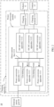
- FIG. 1 is a diagram of a structure of a charging system 10 according to an embodiment of this application.
- FIG. 2 is a diagram of an electrical connection of the charging system 10 shown in FIG. 1 .
- a power transmission line is represented by a solid connection line in FIG. 2 .
- a solid connection line between an external power grid 20 and a power conversion apparatus 1111 in FIG. 2 represents a power transmission line for the external power grid 20 to input an alternating current to the power conversion apparatus 1111.
- the charging system 10 may include a charging apparatus 11 and a vehicle 12.
- the charging apparatus 11 may include a power conversion module 111 and at least one charging terminal 112 connected to the power conversion module 111, and each of the at least one charging terminal 112 is connected to the vehicle 12.
- one charging terminal 112 may be connected to one vehicle 12, or a plurality of charging terminals 112 may be connected to one vehicle 12.
- the power conversion module 111 may be configured to: receive an alternating current input by the external power grid 20, convert the alternating current into a stable direct current, and transmit the stable direct current to the charging terminal 112.
- the charging terminal 112 may transmit, to the vehicle 12, the stable direct current converted by the power conversion module 111, to charge the vehicle 12.
- the power conversion module 111 may include a plurality of power conversion apparatuses 1111, a plurality of DC-DC conversion apparatuses 1112, and a direct current bus 1113.
- Input ends of the plurality of power conversion apparatuses 1111 may be connected to the external power grid 20, and output ends of the plurality of power conversion apparatuses 1111 may be connected to the direct current bus 1113.
- the plurality of power conversion apparatuses 1111 may be connected in parallel between the external power grid 20 and the direct current bus 1113.
- the plurality of power conversion apparatuses 111 may be configured to receive an alternating current from the external power grid 20, convert the alternating current into a direct current, and output the direct current through the direct current bus 1113.
- the power conversion apparatus 111 may be an AC-DC conversion apparatus.
- An input end of the DC-DC conversion apparatus 1112 may be connected to the direct current bus 1113, and an output end of the DC-DC conversion apparatus 1112 may be connected to the charging terminal 112.
- the DC-DC conversion apparatus 1112 may receive, through the direct current bus 1113, direct currents output by the plurality of power conversion apparatuses 1111, further convert the direct currents into direct currents applicable to the vehicle 12, and transmit the direct currents to the vehicle 12 by using the charging terminal 112, to charge the vehicle 12.
- the charging terminal 112 may include a housing, a human-computer interaction interface, a charging control unit, a metering and charging unit, and the like.
- the charging terminal 112 may be configured to perform information interaction, energy transmission, metering and charging, and the like with the vehicle 12.
- the vehicle 12 may be a transportation means driven by electric energy to travel.
- the vehicle 12 may be a new energy vehicle.
- the new energy vehicle may be a pure electric vehicle (pure electric vehicle/battery electric vehicle, pure EV/battery EV), a hybrid electric vehicle (hybrid electric vehicle, HEV), a range extended electric vehicle (range extended electric vehicle, REEV), a plug-in hybrid electric vehicle (plug-in hybrid electric vehicle, PHEV), or the like.
- the plurality of power conversion apparatuses 1111 are connected in parallel, and each power conversion apparatus 1111 converts power of the alternating current output by the external power grid 20, to improve an alternating current-direct current power conversion capability of the charging apparatus 11. In this way, high-power charging of the vehicle 12 by the charging apparatus 11 is implemented.
- the power conversion apparatus 1111 is usually non-isolated, and a circulating current (as shown by a dashed arrow in FIG. 2 ) is easily generated between the plurality of power conversion apparatuses 1111 connected in parallel.
- the circulating current may be usually classified into a high-frequency circulating current component and a low-frequency circulating current component.
- the high-frequency circulating current component is mainly caused by asynchronization of carrier signals of the plurality of power conversion apparatuses 1111.
- the low-frequency circulating current component is mainly caused by inconsistency of modulated wave signals caused by differences in hardware parameters, control parameters, and the like of the plurality of power conversion apparatuses 1111.
- both the high-frequency circulating current component and the low-frequency circulating current component cause an increase in a loss of the power conversion apparatus 1111 and a decrease in power conversion efficiency. Consequently, running stability of the charging apparatus 11 is affected.
- a manner of adding an additional hardware isolation device is usually used.
- a passive filter component or an isolation transformer is added at the input end of each power conversion apparatus 1111, to block a path of the circulating current.
- costs and a size of the charging apparatus 11 are additionally increased in the foregoing manner.
- embodiments of this application provide a power conversion apparatus and a charging apparatus, to suppress a circulating current between a plurality of power conversion apparatuses connected in parallel, to improve running stability of the charging apparatus.
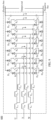
- FIG. 3 is a diagram of a structure of a power conversion apparatus 300 according to an embodiment of this application.
- a solid connection line represents a power transmission line
- a dashed connection line represents a signal transmission line.
- a solid connection line between an input end and an AC-DC conversion circuit 310 represents a power transmission line for transmitting an alternating current from the input end of the power conversion apparatus 300 to the AC-DC conversion circuit 310
- a dashed connection line between a power controller 320 and the AC-DC conversion circuit 310 represents a signal transmission line for transmitting a control signal between the power controller 320 and the AC-DC conversion circuit 310.
- the power conversion apparatus 300 may include the AC-DC conversion circuit 310, the power controller 320, and a circulating current controller 330.
- An input end of the AC-DC conversion circuit 310 may be connected to an external power grid (not shown in the figure), to receive an alternating current output by the external power grid.
- the AC-DC conversion circuit 310 may convert power of the alternating current to obtain a first direct current, and output the first direct current by using an output end of the AC-DC conversion circuit 310.
- the alternating current output by the external power grid may be referred to as a mains supply, and the mains supply is usually a three-phase alternating current.
- the power controller 320 may be connected to the AC-DC conversion circuit 310.
- the power controller 320 may be configured to control the AC-DC conversion circuit 310 to receive the alternating current, convert the alternating current into the first direct current, and output the first direct current.
- the power controller 320 may be any one of a central processor unit (central processor unit, CPU), a network processor (network processor, NP), a digital signal processor (digital signal processor, DSP), a micro controller unit (micro controller unit, MCU), and a programmable logic device (PLD).
- CPU central processor unit
- NP network processor
- DSP digital signal processor
- MCU micro controller unit
- PLD programmable logic device
- the circulating current controller 330 may be configured to send a synchronization signal to another power conversion apparatus through a controller area network (controller area network, CAN) bus, or the circulating current controller 330 may be configured to receive a synchronization signal from another power conversion apparatus through a CAN bus.
- controller area network controller area network, CAN
- CAN controller area network
- the power conversion apparatus 300 may be connected to the another power conversion apparatus in parallel, to form a parallel system. Both the power conversion apparatus 300 and the another power conversion apparatus may be configured to: receive the alternating current output by the external power grid, convert the alternating current into the first direct current, and output the first direct current, so that the parallel system has a high alternating current-direct current power conversion capability.
- carrier synchronization may be implemented, through transmission of the synchronization signal, between the power conversion apparatuses connected in parallel.
- a power conversion apparatus for sending the synchronization signal may be referred to as a primary power conversion apparatus, and a power conversion apparatus for receiving the synchronization signal may be referred to as a secondary power conversion apparatus.
- the power conversion apparatus 300 may be used as the primary power conversion apparatus, and the another power conversion apparatus may be used as the secondary power conversion apparatus.
- the circulating current controller 330 may be communicatively connected, through the CAN bus, to the another power conversion apparatus used as the secondary power conversion apparatus, to send the synchronization signal to the another power conversion apparatus.
- the synchronization signal is used to synchronize a carrier of the another power conversion apparatus with a carrier of the power conversion apparatus 300. It may be understood that, in the parallel system, there may be one or more another power conversion apparatuses used as secondary power conversion apparatuses.
- the power conversion apparatus 300 may be used as the secondary power conversion apparatus, and the another power conversion apparatus may be used as the primary power conversion apparatus.
- the circulating current controller 330 may be communicatively connected, through the CAN bus, to the another power conversion apparatus used as the primary power conversion apparatus, to receive the synchronization signal sent by the another power conversion apparatus.
- the synchronization signal is used to synchronize a carrier of the power conversion apparatus 300 with a carrier of the another power conversion apparatus. It may be understood that, in the parallel system, there may be one or more power conversion apparatuses 300 used as secondary power conversion apparatuses.
- carrier synchronization may mean that phases of carriers of two power conversion apparatuses connected in parallel are the same.
- synchronizing the carrier of the power conversion apparatus 300 with the carrier of the another power conversion apparatus may mean that a phase of the carrier of the power conversion apparatus 300 is the same as that of the carrier of the another power conversion apparatus.
- the circulating current controller 330 may be a DSP.
- the circulating current controller 330 disposed in the power conversion apparatus 300 may be used to send the synchronization signal to the another power conversion apparatus through the CAN bus, or receive, through the CAN bus, the synchronization signal sent by the another power conversion apparatus, so that the carrier of the power conversion apparatus 300 is synchronized with the carrier of the another power conversion apparatus.
- a high-frequency circulating current component in a circulating current between the power conversion apparatuses connected in parallel can be suppressed. This helps reduce a loss of each power conversion apparatus, ensure power conversion efficiency of each power conversion apparatus, and improve running stability of the power conversion apparatuses connected in parallel.
- no additional hardware device needs to be added. Therefore, costs are low, and production is facilitated.
- a plurality of power conversion apparatuses usually communicate and interact with each other by using the Ethernet, to transmit a signal.
- the Ethernet is connection of LAN switches.
- a LAN switch having a large quantity of interfaces is usually required.
- a network topology structure there are a large quantity of interconnection lines, and a topology structure is complex.
- a high-performance LAN switch also causes high costs.
- a LAN switch does not need to be used between the power conversion apparatus 300 and the another power conversion apparatus. Instead, the power conversion apparatus 300 directly communicates and interacts with the another power conversion apparatus through the CAN bus, to transmit the synchronization signal. Therefore, a network topology structure is simpler, communication efficiency is higher, and low-cost production is better facilitated.
- the power conversion apparatus 300 may further include a circulating current detection circuit 340, and the AC-DC conversion circuit 310 may include a plurality of switches.
- the circulating current detection circuit 340 may be connected to the input end of the AC-DC conversion circuit 310 and the circulating current controller 330.
- the circulating current detection circuit 340 may be configured to: detect a circulating current value at the input end of the AC-DC conversion circuit 310 and send the circulating current value to the circulating current controller 330.
- the circulating current value may be a magnitude of a current that flows into the AC-DC conversion circuit 310 from the another power conversion apparatus when the power conversion apparatus 300 is connected to the another power conversion apparatus in parallel.
- the circulating current controller 330 may be connected to the power controller 320, to transmit a signal.
- the circulating current controller 330 may be configured to: receive a first modulated wave from the power controller 320 and adjust the first modulated wave based on the circulating current value obtained from the circulating current detection circuit 340, to obtain a second modulated wave.
- the second modulated wave may be used to determine a drive signal.
- the drive signal is used to control turn-on time of the plurality of switches in the AC-DC conversion circuit 210.
- the circulating current controller 330 may send the second modulated wave obtained through adjustment to the power controller 320, and the power controller 320 may determine the drive signal based on the second modulated wave and the carrier of the power conversion apparatus 300.
- the switch in this embodiment of this application may be one or more of a plurality of types of switching transistors, such as a metal-oxide-semiconductor field-effect transistor (metal-oxide-semiconductor field-effect transistor, MOSFET), a bipolar junction transistor (bipolar junction transistor, BJT), an insulated gate bipolar transistor (insulated gate bipolar transistor, IGBT), or a silicon carbide (SiC) transistor.
- MOSFET metal-oxide-semiconductor field-effect transistor
- BJT bipolar junction transistor
- IGBT insulated gate bipolar transistor
- SiC silicon carbide
- a package form of each switching transistor may be single-transistor package or multi-transistor package.
- the circulating current detection circuit 340 is disposed in the power conversion apparatus 300, so that the circulating current value input to the AC-DC conversion circuit 310 can be detected in real time.
- the circulating current controller 330 may perform, based on the circulating current value, compensation adjustment on the first modulated wave output by the power controller 320, and send the second modulated wave obtained through adjustment to the power controller 320.
- the power controller 320 controls the turn-on time of the plurality of switches in the AC-DC conversion circuit 310 by using the drive signal generated based on the second modulated wave, so that a low-frequency circulating current component in the AC-DC conversion circuit 310 can reach a preset circulating current threshold.
- the preset circulating current threshold may be, for example, 0.
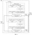
- FIG. 4 is a diagram of a structure of a charging apparatus 400 according to an embodiment of this application. It should be understood that in FIG. 4 , a solid connection line represents a power transmission line, and a dashed connection line represents a signal transmission line.
- the charging apparatus 400 may include a direct current bus 410 and a plurality of power conversion apparatuses.
- the plurality of power conversion apparatuses may be disposed in parallel between an external power grid (not shown in the figure) and the direct current bus 410.
- the direct current bus 410 may include a positive bus and a negative bus, and an output end of each of the plurality of power conversion apparatuses may be connected to the positive bus and the negative bus.
- the plurality of power conversion apparatuses may include a primary power conversion apparatus 420 and at least one secondary power conversion apparatus 430.
- the primary power conversion apparatus 420 and the secondary power conversion apparatus 430 may be separately the power conversion apparatus 300.
- the primary power conversion apparatus 420 and the secondary power conversion apparatus 430 may be preset in the plurality of power conversion apparatuses connected in parallel.
- a power conversion apparatus with a smallest apparatus identification number may be set as the primary power conversion apparatus 420
- another power conversion apparatus other than the power conversion apparatus with the smallest apparatus identification number may be set as the secondary power conversion apparatus 430 based on an apparatus identification number.
- the plurality of power conversion apparatuses may include the primary power conversion apparatus 420 and one, two, or three secondary power conversion apparatuses 430. It should be understood that, for ease of description and understanding, an example in which the plurality of power conversion apparatuses include the primary power conversion apparatus 420 and one secondary power conversion apparatus 430 is used for description in this embodiment of this application.
- the primary power conversion apparatus 420 may include an AC-DC conversion circuit 421, a power controller 422, and a primary circulating current controller 423.
- the secondary power conversion apparatus 430 may include an AC-DC conversion circuit 431, a power controller 432, and a secondary circulating current controller 433. Input ends of the AC-DC conversion circuit 421 and the AC-DC conversion circuit 431 may be connected to the external power grid in parallel, and output ends of the AC-DC conversion circuit 421 and the AC-DC conversion circuit 431 may be connected to the direct current bus 410 in parallel. In other words, the AC-DC conversion circuit 421 and the AC-DC conversion circuit 431 may be connected in parallel between the external power grid and the direct current bus 410.
- the primary circulating current controller 423 may be communicatively connected to the secondary circulating current controller 433 through a CAN bus, so that the primary circulating current controller 423 can send a synchronization signal to the secondary circulating current controller 433 through the CAN bus.
- the synchronization signal may be used to synchronize a carrier of the secondary power conversion apparatus 430 with a carrier of the primary power conversion apparatus 420.
- the primary power conversion apparatus 420 may include an isolator 4241, a CAN transceiver 4242, and a CAN interface 4243
- the secondary power conversion apparatus 430 may include an isolator 4341, a CAN transceiver 4342, and a CAN interface 4343.
- the primary circulating current controller 423, the isolator 4241, the CAN transceiver 4242, and the CAN interface 4243 are sequentially connected to each other.
- the secondary circulating current controller 433, the isolator 4341, the CAN transceiver 4342, and the CAN interface 4343 are sequentially connected to each other.
- the CAN interface 4243 and the CAN interface 4343 are separately connected to the CAN bus, so that the primary circulating current controller 423 can communicate and interact with the secondary circulating current controller 433 through the CAN bus, to transmit the synchronization signal.
- the primary circulating current controller 423 and the secondary circulating current controller 433 may implement carrier synchronization between the primary power conversion apparatus 420 and the secondary power conversion apparatus 430 based on a plurality of timers and by using the synchronization signal.
- the following describes an example of a specific manner in which the primary circulating current controller 423 and the secondary circulating current controller 433 implement carrier synchronization based on the plurality of timers and by using the synchronization signal.
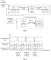
- FIG. 5 is a diagram of a specific example of the primary circulating current controller 423 and the secondary circulating current controller 433 according to an embodiment of this application. It should be understood that a dashed connection line in FIG. 5 represents a signal transmission line.
- the primary circulating current controller 423 may include a first primary timer 4231, a first secondary timer 4232, and a synchronization timer 4233
- the secondary circulating current controller 433 may include a second primary timer 4331 and a second secondary timer 4332.
- the first primary timer 4231 is connected to the first secondary timer 4231.
- the second primary timer 4331 is connected to the second secondary timer 4332.
- the first primary timer 4231 and the second primary timer 4331 are separately connected to the synchronization timer 4233.
- the synchronization timer 4233 may be configured to: when a count value of the synchronization timer 4233 is a first period value, send the synchronization signal to the first primary timer 4231 and the second primary timer 4331.
- the first period value may be a period value of the synchronization signal.
- the first primary timer 4231 may be configured to adjust, based on edge triggering of the synchronization signal, a period of the carrier of the primary power conversion apparatus 420 to be synchronized with a target carrier period.
- the second primary timer 4331 may be further configured to adjust, based on edge triggering of the synchronization signal, a period of the carrier of the secondary power conversion apparatus 430 to be synchronized with the target carrier period. In this way, both the period of the carrier of the primary power conversion apparatus 420 and the period of the carrier of the secondary power conversion apparatus 430 are synchronized with the target carrier period. In other words, the carrier of the primary power conversion apparatus 420 is synchronized with the carrier of the secondary power conversion apparatus 430.
- the target carrier period may be a preset carrier period, and a period value of the target carrier period may be flexibly adjusted based on an actual design requirement.
- the target carrier period and a target count value may be preset on the first primary timer 4231 and the second primary timer 4331.
- the target count value may be a count value ranging from 0 to a preset period in the target carrier period.
- the preset period may be, for example, 1/2 or 1/3 of the period value of the target carrier period.
- the first primary timer 4231 may obtain a first count value based on edge triggering of the synchronization signal.
- the first count value may be a count value ranging from 0 to a preset period in a primary carrier period.
- the primary carrier period may be the period of the carrier of the primary power conversion apparatus 420.
- the first primary timer 4231 may compare the first count value with the target count value to fine-tune a period value of the primary carrier period, so that the primary carrier period is synchronized with the target carrier period, that is, the period of the carrier of the primary power conversion apparatus 420 is synchronized with the target carrier period.
- the second primary timer 4331 may obtain a second count value based on edge triggering of the synchronization signal.
- the second count value may be a count value ranging from 0 to a preset period in a secondary carrier period.
- the secondary carrier period may be the period of the carrier of the secondary power conversion apparatus 430.
- the second primary timer 4331 may compare the second count value with the target count value to fine-tune a period value of the secondary carrier period, so that the secondary carrier period is synchronized with the target carrier period, that is, the period of the carrier of the secondary power conversion apparatus 430 is synchronized with the target carrier period.
- the carrier of the primary power conversion apparatus 420 is synchronized with the carrier of the secondary power conversion apparatus 430.
- the edge triggering of the synchronization signal may be triggering at a rising edge of the synchronization signal, or may be triggering at a falling edge of the synchronization signal.
- the first primary timer 4231 and the second primary timer 4331 may respectively obtain the first count value and the second count value based on triggering at the rising edge of the synchronization signal.
- both the primary circulating current controller 423 and the secondary circulating current controller 433 include the synchronization timer, so that based on actual production and design requirements, any one of the plurality of power conversion apparatuses in the charging apparatus 400 can transmit the synchronization signal as the primary power conversion apparatus.
- the first primary timer 4231 may be configured to send a first trigger signal to the first secondary timer 4232 when a count value of the first primary timer 4231 is the period value of the target carrier period.
- the first trigger signal may indicate to reset a count value of the first secondary timer 4232.
- the first secondary timer 4232 may reset the count value of the first secondary timer 4232, so that the first primary timer 4231 is synchronized with the first secondary timer 4232, and the primary timer and the secondary timer in the primary power conversion apparatus 420 can output signals with a same frequency and a same phase. In this way, signals in the primary power conversion apparatus 420 are synchronized.
- the second primary timer 4331 may be configured to send a second trigger signal to the second secondary timer 4332 when a count value of the second primary timer 4331 is the period value of the target carrier period.
- the second trigger signal may indicate to reset a count value of the second secondary timer 4332, so that the second primary timer 4331 is synchronized with the second secondary timer 4332, and the primary timer and the secondary timer in the secondary power conversion apparatus 430 output signals with a same frequency and a same phase. In this way, signals in the secondary power conversion apparatus 430 are synchronized.
- resetting a count value may mean resetting the count value to 0.
- first secondary timers 4232 and second secondary timers 4332 there may be separately a plurality of first secondary timers 4232 and a plurality of second secondary timers 4332, and quantities of first secondary timers 4232 and second secondary timers 4332 are equal. For example, there may be separately five first secondary timers 4232 and second secondary timers 4332, or there may be separately six first secondary timers 4232 and second secondary timers 4332.
- the primary timer and the secondary timer may be high resolution timers (high resolution timers, HRTIMs).
- the plurality of power conversion apparatuses in the charging apparatus 400 are set as the primary power conversion apparatus and the at least one secondary power conversion apparatus, and the primary circulating current controller of the primary power conversion apparatus sends the synchronization signal to the secondary circulating current controller of the secondary power conversion apparatus through the CAN bus, so that the carrier of each secondary power conversion apparatus is synchronized with the carrier of the primary power conversion apparatus.
- the primary circulating current controller of the primary power conversion apparatus sends the synchronization signal to the secondary circulating current controller of the secondary power conversion apparatus through the CAN bus, so that the carrier of each secondary power conversion apparatus is synchronized with the carrier of the primary power conversion apparatus.
- a high-frequency circulating current component in a circulating current between the power conversion apparatuses in the charging apparatus 400 can be suppressed. This helps reduce a loss of each power conversion apparatus, ensure power conversion efficiency of each power conversion apparatus, and improve running stability of the charging apparatus.
- no additional hardware device needs to be added. Therefore, costs are low, and production is facilitated.
- each power conversion apparatus in the charging apparatus 400 communicates and interacts with each other through the CAN bus, to transmit the synchronization signal. Therefore, a network topology structure is simple, communication efficiency is high, and low-cost production is better facilitated.
- FIG. 7 is a diagram of a structure of another charging apparatus 400 according to an embodiment of this application. It should be understood that in FIG. 7 , a solid connection line represents a power transmission line, and a dashed connection line represents a signal transmission line.
- the charging apparatus 400 shown in FIG. 7 includes most technical features of the charging apparatus 400 shown in FIG. 4 to FIG. 6 . The following mainly describes differences between FIG. 7 and FIG. 4 . Most same content thereof is not described again.
- the primary power conversion apparatus 420 may further include a circulating current detection circuit 424, and the AC-DC conversion circuit 421 may include a plurality of switches.
- the circulating current detection circuit 424 may be connected to an input end of the AC-DC conversion circuit 421 and the primary circulating current controller 423.
- the circulating current detection circuit 424 may be configured to: detect a circulating current value at the input end of the AC-DC conversion circuit 421 and send the circulating current value to the primary circulating current controller 423.
- the primary circulating current controller 423 may be configured to: receive a first modulated wave from the power controller 422 and adjust the first modulated wave based on the circulating current value, to obtain a second modulated wave.
- the second modulated wave may be used to determine a drive signal.
- the drive signal is used to control turn-on time of the plurality of switches in the AC-DC conversion circuit 421.
- the primary circulating current controller 423 may be specifically configured to:
- the preset circulating current threshold may be 0.
- the operation adjustment may include, for example, but is not limited to, any one of a proportion (proportion, P) operation, a proportion integral (proportion integral, PI) operation, and a proportion integral derivative (proportion integral derivative, PID) operation.
- the primary circulating current controller 423 may determine, by using the preset circulating current threshold as a target, a deviation between the circulating current value and the preset circulating current threshold, and determine, based on the deviation, the first compensation amount for adjusting the first modulated wave output by the power controller 422. In this way, compensation adjustment is performed on the first modulated wave by using the first compensation amount, to obtain the second modulated wave.
- the primary circulating current controller 423 may be further configured to send the second modulated wave to the power controller 422.
- the power controller 422 may determine the drive signal based on the second modulated wave and the carrier of the primary power conversion apparatus 420.
- the power controller 422 may include a pulse width modulation (pulse width modulation, PWM) unit.
- the PWM unit may be configured to: compare the second modulated wave obtained through compensation adjustment with the carrier of the primary power conversion apparatus 420, and adjust a duty cycle of the drive signal, so that the PWM unit can control the turn-on time of the plurality of switches in the AC-DC conversion circuit 421 by using the drive signal. In this way, the low-frequency circulating current component in the AC-DC conversion circuit 421 reaches the preset circulating current threshold.
- the secondary power conversion apparatus 430 may further include a circulating current detection circuit 434.
- the circulating current detection circuit 434 may be connected to an input end of the AC-DC conversion circuit 431 and the secondary circulating current controller 433.
- each power conversion apparatus (for example, the primary power conversion apparatus 420 and the secondary power conversion apparatus 430) is provided with the circulating current detection circuit, detects, through the circulating current detection circuit, a circulating current value input to the AC-DC conversion circuit, in real time, and transmits the circulating current value to the circulating current controller.
- the circulating current controller may use the preset circulating current threshold as a target, perform, based on the circulating current value, compensation adjustment on a modulated wave output by the power controller, and send the modulated wave obtained through adjustment to the power controller.
- the power controller generates the drive signal based on the adjusted modulated wave, to control the turn-on time of the plurality of switches in the AC-DC conversion circuit, so that the low-frequency circulating current component in the AC-DC conversion circuit can reach the preset circulating current threshold. This helps suppress a low-frequency circulating current component in a circulating current in the charging apparatus 400, and improve running stability of the charging apparatus 400.
- the charging apparatus 400 may further include an energy storage unit 440.
- the energy storage unit 440 may be connected to the direct current bus 410, so that an output end of the AC-DC conversion circuit 421 and an output end of the AC-DC conversion circuit 431 can be connected to the energy storage unit 440 through the direct current bus 410.
- First direct currents output by the AC-DC conversion circuit 421 and the AC-DC conversion circuit 431 may be transmitted to the energy storage unit 440 through the direct current bus 410, to form an energy pool.
- the energy storage unit 440 may be, for example, a photovoltaic apparatus and/or an energy storage apparatus.
- the photovoltaic apparatus in this embodiment of this application may be any manner in which a photovoltaic function can be implemented.
- the photovoltaic apparatus may include at least one photovoltaic array. Each of the at least one photovoltaic array is connected to the direct current bus 410.
- the energy storage apparatus in this embodiment of this application may be any manner in which an electric energy storage function can be implemented.
- the energy storage apparatus may be, for example, an energy storage battery pack or an energy storage converter.
- the energy storage unit in light and storage access scenarios, is superimposed on the direct current bus, so that first direct currents output by the plurality of power conversion apparatuses can be stored in the energy storage unit. In this way, light and storage are superimposed on a side of the direct current bus.
- the charging apparatus 400 is configured to charge a vehicle, energy in the energy storage unit may be converted into a direct current applicable to the vehicle. Energy conversion efficiency is high.
- FIG. 8 is a specific example of a charging apparatus 500 according to an embodiment of this application. It should be understood that in FIG. 8 , a solid connection line represents a power transmission line, and a dashed connection line represents a signal transmission line.
- the charging apparatus 500 may be a specific example of the charging apparatus 400 shown in FIG. 7 .
- the charging apparatus 500 may include a primary power conversion apparatus 510, a secondary power conversion apparatus 520, a positive bus, and a negative bus.
- the primary power conversion apparatus 510 may include an AC-DC conversion circuit 511, a power controller 512, a primary circulating current controller 513, and a circulating current detection circuit 514.
- the following describes a specific example of a partial structure in the primary power conversion apparatus 510.
- the AC-DC conversion circuit 511 may be a three-phase T-type interleaved Vienna rectifier circuit.
- the AC-DC conversion circuit 511 may include an input end, three dual-path power factor correction (power factor correction, PFC) conversion circuits (namely, a dual-path PFC conversion circuit 1, a dual-path PFC conversion circuit 2, and a dual-path PFC conversion circuit 3), and a capacitor circuit.
- PFC power factor correction
- the input end may include three phase wires: a first phase wire U, a second phase wire V, and a third phase wire W.
- Each phase wire may be configured to receive a corresponding one-phase alternating current, so that the AC-DC conversion circuit 511 can receive a three-phase alternating current from an external power grid.
- the first phase wire U, the second phase wire V, and the third phase wire W may be separately connected to one dual-path PFC conversion circuit, and each dual-path PFC conversion circuit is further connected to a capacitor midpoint of the capacitor circuit.
- a first end of the capacitor circuit may be connected to the positive bus, and a second end of the capacitor branch circuit may be connected to the negative bus.
- Each dual-path PFC conversion circuit has a same structure.
- Each dual-path PFC conversion circuit may include an inductor, two windings of an autotransformer, two switch bridge arms, and two diode bridge arms.
- the capacitor circuit may include a capacitor C 1 and a capacitor C 2 that are connected in series.
- the dual-path PFC conversion circuit 1 may include an inductor L A , two windings T A1 and T A2 of an autotransformer, a switch bridge arm 1, a switch bridge arm 2, a diode bridge arm 1, and a diode bridge arm 2.
- the switch bridge arm 1 includes a switching transistor S a1 and a switching transistor S a2 that are connected in series.
- the switch bridge arm 2 includes a switching transistor S a3 and a switching transistor S a4 that are connected in series.
- the diode bridge arm 1 includes a diode D a1 and a diode D a3 that are connected in series.
- the diode bridge arm 2 includes a diode D a2 and a diode D a4 that are connected in series.
- a left end of the inductor L A is connected to the first phase wire U, and a right end of the inductor L A is connected to left ends of the windings T A1 and T A2 of the autotransformer.
- a right end of the winding T A1 of the autotransformer may be connected to both a left end of the switch bridge arm 1 and the diode bridge arm 1, and a right end of the winding T A2 of the autotransformer may be connected to both a left end of the switch bridge arm 2 and the diode bridge arm 2.
- a right end of the switch bridge arm 1 and a right end of the switch bridge arm 2 may be connected to the capacitor midpoint of the capacitor circuit.
- the diode bridge arm 1 and the diode bridge arm 2 may be connected in parallel between an upper end and a lower end of the capacitor circuit.
- the upper end of the capacitor circuit may be connected to the positive bus, and the lower end of the capacitor circuit may be connected to the negative bus.
- the dual-path PFC conversion circuit 2 may include an inductor L B , two windings T B1 and T B2 of an autotransformer, a switching transistor S b1 and a switching transistor S b2 that are connected in series, a switching transistor S b3 and a switching transistor S b4 that are connected in series, a diode D b1 and a diode D b3 that are connected in series, and a diode D b2 and a diode D b4 that are connected in series.
- a specific connection of the foregoing circuit components is similar to a connection structure of the PFC conversion circuit 1. For details, refer to the related descriptions of the foregoing PFC conversion circuit 1. Details are not described herein again.
- the PFC conversion circuit 3 may include an inductor Lc, two windings T c1 and T c2 of an autotransformer, a switching transistor S c1 and a switching transistor S c2 that are connected in series, a switching transistor S c3 and a switching transistor S c4 that are connected in series, a diode D c1 and a diode D c3 that are connected in series, and a diode D c2 and a diode D c4 that are connected in series.
- a specific connection of the foregoing circuit components is similar to a connection structure of the PFC conversion circuit 1. For details, refer to the related descriptions of the foregoing PFC conversion circuit 1. Details are not described herein again.
- At least some of the diodes may be replaced with controllable switching transistors.
- the three dual-path PFC conversion circuits may be configured to receive the three-phase alternating current from the external power grid, convert the three-phase alternating current into a first direct current, and output the first direct current through the positive bus and the negative bus.
- the primary circulating current controller 513 may include a comparison unit 5131, an operation control unit 5132, and a compensation unit 5133.
- the comparison unit 5131 may be configured to determine a circulating current deviation based on a circulating current value and a preset circulating current threshold.
- the operation control unit 5132 may be configured to perform operation adjustment on the circulating current deviation, to obtain a first compensation amount.
- the operation control unit 5132 may be, for example, any one of a P controller, a PI controller, and a PID controller.
- the compensation unit 5133 may be configured to perform superposition processing on the first compensation amount and a first modulated wave output by the power controller 512, to adjust and compensate for the first modulated wave, to obtain a second modulated wave.
- the first modulated wave and the second modulated wave may be three-phase modulated waves.
- the first modulated wave may include a first A-phase modulated wave, a first B-phase modulated wave, and a first C-phase modulated wave.
- the second modulated wave may include a second A-phase modulated wave, a second B-phase modulated wave, and a second C-phase modulated wave.
- the compensation unit 5133 may transmit the obtained three-phase second modulated wave to the power controller 512, so that the power controller 512 can determine a drive signal based on the second modulated wave and a carrier of the primary power conversion apparatus 510.
- the drive signal may be a three-phase drive signal, and the drive signal may include an A-phase drive signal, a B-phase drive signal, and a C-phase drive signal.
- Each phase drive signal may be used to control turn-on time of a plurality of switching transistors in two switch bridge arms in one dual-path PFC conversion circuit.
- the A-phase drive signal may be used to control turn-on time of the switching transistors S a1 and S a2 in the dual-path PFC conversion circuit 1
- the B-phase drive signal may be used to control turn-on time of the switching transistors S b1 and S b2 in the dual-path PFC conversion circuit 2
- the C-phase drive signal may be used to control turn-on time of the switching transistors S c1 and S c2 in the dual-path PFC conversion circuit 3, so that low-frequency circulating current components in the three dual-path PFC conversion circuits can reach the preset circulating current threshold.
- a synchronization timer (not shown in the figure) in the primary circulating current controller 513 may further send a synchronization signal to the secondary circulating current controller 523 through a CAN bus, to synchronize the primary power conversion apparatus 510 with the secondary power conversion apparatus 510.
- the circulating current detection circuit 514 may be connected to the input end of the AC-DC conversion circuit 511, to detect, in real time, a circulating current value input to the AC-DC conversion circuit 511.
- an input end of the circulating current detection circuit 514 may be a single-phase input or a multiphase input.
- the circulating current detection circuit 514 may be a three-phase input.
- the secondary power conversion apparatus 520 may include an AC-DC conversion circuit 521, a power controller 522, a secondary circulating current controller 523, and a circulating current detection circuit 524.
- a topology structure of the secondary power conversion apparatus 520 is the same as a topology structure of the primary power conversion apparatus 510.
- the AC-DC conversion circuit 521, the power controller 522, the secondary circulating current controller 523, and the circulating current detection circuit 524 refer to the related descriptions of the foregoing primary power conversion apparatus 510. Details are not described herein again.
- FIG. 9 is a specific example of an AC-DC conversion circuit 600 according to an embodiment of this application. It should be understood that the AC-DC conversion circuit 600 may be the AC-DC conversion circuit 511 and the AC-DC conversion circuit 512.
- the AC-DC conversion circuit 600 may also include an input end, a three-phase dual-path PFC conversion circuit (namely, a dual-path PFC conversion circuit 1, a dual-path PFC conversion circuit 2, and a dual-path PFC conversion circuit 3), and a capacitor circuit.
- a three-phase dual-path PFC conversion circuit namely, a dual-path PFC conversion circuit 1, a dual-path PFC conversion circuit 2, and a dual-path PFC conversion circuit 3
- a capacitor circuit namely, a dual-path PFC conversion circuit 1, a dual-path PFC conversion circuit 2, and a dual-path PFC conversion circuit 3
- the AC-DC conversion circuit 600 may be a three-phase I-type interleaved Vienna rectifier circuit.
- each dual-path PFC conversion circuit may include an inductor, two windings of an autotransformer, and two switch bridge arms.
- the dual-path PFC conversion circuit 1 is used as an example.
- the PFC conversion circuit 1 may include an inductor L A , two windings T A1 and T A2 of an autotransformer, a switch bridge arm 1, and a switch bridge arm 2.
- the switch bridge arm 1 includes switching transistors S a1 and S a2 , and diodes D a1 , D a2 , D a3 , and D a4 .
- the switch bridge arm 2 includes switching transistors S a3 and S a4 , and diodes D a5 , D a6 , D a7 , and D a8 .
- a left end of the inductor L A is connected to a first phase wire U, and a right end of the inductor L A is connected to left ends of the windings T A1 and T A2 of the autotransformer.
- a right end of the winding T A1 of the autotransformer may be connected to the switch bridge arm 1, and a right end of the winding T A2 of the autotransformer may be connected to the switch bridge arm 2.
- the switch bridge arm 1 and the switch bridge arm 2 may be connected in parallel between an upper end and a lower end of the capacitor circuit.
- the dual-path PFC conversion circuit 2 may include an inductor LB , two windings T B1 and T B2 of an autotransformer, switching transistors S b1 , S b2 , S b3 , and S b4 , and diodes D b1 , D b2 , D b3 , D b4 , D b5 , D b6 , D b7 , and D b8 .
- a specific connection of the foregoing circuit components is similar to a connection structure of the dual-path PFC conversion circuit 1. For details, refer to the related descriptions of the dual-path PFC conversion circuit 1. Details are not described herein again.
- the PFC conversion circuit 3 may include an inductor Lc, two windings T c1 and T c2 of an autotransformer, switching transistors S c1 , S c2 , S c3 , and S c4 , and diodes D c1 , D c2 , D c3 , D c4 , D c5 , D c6 , D c7 and D c8 .
- a specific connection of the foregoing circuit components is similar to a connection structure of the dual-path PFC conversion circuit 1. For details, refer to the related descriptions of the dual-path PFC conversion circuit 1. Details are not described herein again.
- At least some of the diodes may be replaced with controllable switching transistors.
- FIG. 10 is a specific example of an AC-DC conversion circuit 700 according to an embodiment of this application. It should be understood that the AC-DC conversion circuit 700 may be the AC-DC conversion circuit 511 and the AC-DC conversion circuit 512.
- the AC-DC conversion circuit 700 may also include an input end, a three-phase dual-path PFC conversion circuit (namely, a dual-path PFC conversion circuit 1, a dual-path PFC conversion circuit 2, and a dual-path PFC conversion circuit 3), and a capacitor circuit.
- a three-phase dual-path PFC conversion circuit namely, a dual-path PFC conversion circuit 1, a dual-path PFC conversion circuit 2, and a dual-path PFC conversion circuit 3
- a capacitor circuit namely, a dual-path PFC conversion circuit 1, a dual-path PFC conversion circuit 2, and a dual-path PFC conversion circuit 3
- the AC-DC conversion circuit 700 may be a three-phase full-bridge rectifier circuit.
- each dual-path PFC conversion circuit may include an inductor, two windings of an autotransformer, and two switch bridge arms.
- the capacitor circuit may include a capacitor C 1 and a capacitor C 2 that are connected in series.
- the dual-path PFC conversion circuit 1 may include an inductor L A , two windings T A1 and T A2 of an autotransformer, a switch bridge arm 1, and a switch bridge arm 2.
- the switch bridge arm 1 includes a switching transistor S a1 and a switching transistor S a2 that are connected in series.
- the switch bridge arm 2 includes a switching transistor S a3 and a switching transistor S a4 that are connected in series.
- a left end of the inductor L A is connected to a first phase wire U, and a right end of the inductor L A is connected to left ends of the windings T A1 and T A2 of the autotransformer.
- a right end of the winding T A1 of the autotransformer may be connected to the switch bridge arm 1, and a right end of the winding T A2 of the autotransformer may be connected to the switch bridge arm 2.
- the switch bridge arm 1 and the switch bridge arm 2 may be connected in parallel between an upper end and a lower end of the capacitor circuit.
- the dual-path PFC conversion circuit 2 may include an inductor L B , two windings T B1 and T B2 of an autotransformer, and switching transistors S b1 , S b2 , S b3 , and S b4 .
- a specific connection of the foregoing circuit components is similar to a connection structure of the dual-path PFC conversion circuit 1. For details, refer to the related descriptions of the dual-path PFC conversion circuit 1. Details are not described herein again.
- the PFC conversion circuit 3 may include an inductor Lc, two windings T c1 and T c2 of an autotransformer, and switching transistors S c1 , S c2 , S c3 , and S c4 .
- Lc inductor
- S c1 , S c2 , S c3 , and S c4 switching transistors S c1 , S c2 , S c3 , and S c4 .
- the three-phase full-bridge rectifier circuit used by the AC-DC conversion circuit 700 has a simpler power topology structure, so that the AC-DC conversion circuit 700 is better applicable to a scenario in which a switching transistor in a rectifier circuit is a high-voltage switching transistor, for example, a SiC transistor.
- AC-DC conversion circuit may use another circuit structure based on actual production and design requirements.
- FIG. 11 is a diagram of a structure of another charging apparatus 400 according to an embodiment of this application. It should be understood that in FIG. 11 , a solid connection line represents a power transmission line, and a dashed connection line represents a signal transmission line.
- the charging apparatus 400 shown in FIG. 11 includes most technical features of the charging apparatus 400 shown in FIG. 4 and FIG. 7 .
- the following mainly describes differences between FIG. 11 and FIG. 4 and FIG. 7 . Most same content thereof is not described again.
- the charging apparatus 400 may further include a DC-DC conversion apparatus 450.
- An input end of the DC-DC conversion apparatus 450 may be connected to a direct current bus 410, and an output end of the DC-DC conversion apparatus 450 may be configured to be connected to a vehicle.
- the DC-DC conversion apparatus 450 may be configured to receive, through the direct current bus 410, first direct currents output by a primary power conversion apparatus 420 and a secondary power conversion apparatus 430, convert the first direct currents into second direct currents, and output the second direct currents to the vehicle, to supply power to the vehicle.
- the primary power conversion apparatus 420 may include an AC-DC conversion circuit 421, and the secondary power conversion apparatus 430 may include an AC-DC conversion circuit 43.
- the AC-DC conversion circuit 421 and the AC-DC conversion circuit 431 are connected in parallel between an external power grid and the direct current bus 410, and are respectively configured to convert the received alternating currents into the first direct currents, and output the first direct currents through the direct current bus 410.
- the DC-DC conversion apparatus 450 may receive the first direct currents through the direct current bus 410, convert the first direct currents into the second direct currents, and output the second direct currents to the vehicle.
- the DC-DC conversion apparatus 450 may directly receive, through the direct current bus 410, the first direct currents output by the AC-DC conversion circuit 421 and the AC-DC conversion circuit 431.
- the charging apparatus 400 may further include an energy storage unit 440.
- the energy storage unit 440 may be connected to the direct current bus 410.
- the first direct currents output by the AC-DC conversion circuit 421 and the AC-DC conversion circuit 431 may be transmitted to the energy storage unit 440 through the direct current bus 410.
- the DC-DC conversion apparatus 450 may receive the first direct currents from the energy storage unit 440 through the direct current bus 410.
- DC-DC conversion apparatuses 450 there may be one or more DC-DC conversion apparatuses 450 in the charging apparatus 400.
- a quantity of DC-DC conversion apparatuses 450 may be the same as or different from a quantity of power conversion apparatuses in the charging apparatus 400 (namely, a sum of quantities of primary power conversion apparatuses 420 and at least one secondary power conversion apparatus 430).
- the charging apparatus 400 may further include a power allocation unit 460.
- the power allocation unit 460 may be connected between output ends of the plurality of DC-DC conversion apparatuses 450 and the vehicle.
- the power allocation unit 460 may be configured to dynamically allocate, based on charging power actually required by the vehicle, the second direct currents output by the plurality of DC-DC conversion apparatuses 450.
- the power allocation unit 460 may use the second direct currents output by the plurality of DC-DC conversion apparatuses 450, to charge one vehicle, or the power allocation unit 460 may use the second direct currents output by the plurality of DC-DC conversion apparatuses 450, to charge a plurality of vehicles.
- the charging apparatus 400 may further include at least one charging terminal 470.
- the at least one charging terminal 470 is connected to the output end of the DC-DC conversion apparatus 450.
- Each of the at least one charging terminal 470 is configured to connect to a vehicle, so that the DC-DC conversion apparatus 450 charges, by using each charging terminal 470, the vehicle connected to the charging terminal 470.
- each charging terminal 470 may be connected to at least one DC-DC conversion apparatus 450 in the charging apparatus 400.
- An embodiment of this application further provides a charging system.
- the charging system may include the foregoing charging apparatus 400 and a vehicle.
- the charging apparatus 400 may charge the vehicle.
- FIG. 1 and FIG. 2 Details are not described herein again.
Landscapes
- Engineering & Computer Science (AREA)
- Power Engineering (AREA)
- Transportation (AREA)
- Mechanical Engineering (AREA)
- Computer Networks & Wireless Communication (AREA)
- Signal Processing (AREA)
- Inverter Devices (AREA)
- Charge And Discharge Circuits For Batteries Or The Like (AREA)
Applications Claiming Priority (1)
| Application Number | Priority Date | Filing Date | Title |
|---|---|---|---|
| CN202310810698.2A CN116827086A (zh) | 2023-07-03 | 2023-07-03 | 功率转换装置和充电装置 |
Publications (2)
| Publication Number | Publication Date |
|---|---|
| EP4506204A2 true EP4506204A2 (de) | 2025-02-12 |
| EP4506204A3 EP4506204A3 (de) | 2025-06-11 |
Family
ID=88116452
Family Applications (1)
| Application Number | Title | Priority Date | Filing Date |
|---|---|---|---|
| EP24184467.9A Pending EP4506204A3 (de) | 2023-07-03 | 2024-06-25 | Leistungsumwandlungsvorrichtung und ladevorrichtung |
Country Status (3)
| Country | Link |
|---|---|
| US (1) | US20250015699A1 (de) |
| EP (1) | EP4506204A3 (de) |
| CN (1) | CN116827086A (de) |
Cited By (1)
| Publication number | Priority date | Publication date | Assignee | Title |
|---|---|---|---|---|
| EP4583383A1 (de) * | 2024-01-04 | 2025-07-09 | Delta Electronics, Inc. | Kreisstromunterdrückungsverfahren und schaltersteuerungsvorrichtung |
Families Citing this family (3)
| Publication number | Priority date | Publication date | Assignee | Title |
|---|---|---|---|---|
| CN120156371A (zh) * | 2023-12-14 | 2025-06-17 | 华为数字能源技术有限公司 | 充电设备 |
| CN117937705A (zh) * | 2023-12-22 | 2024-04-26 | 华为数字能源技术有限公司 | 一种功率转换装置及充电设备 |
| EP4683196A1 (de) * | 2024-07-20 | 2026-01-21 | Vertiv Corporation | Systeme und verfahren zur synchronisation von nichtisolierten aufwärtswandlern in einer stromversorgung |
Family Cites Families (8)
| Publication number | Priority date | Publication date | Assignee | Title |
|---|---|---|---|---|
| US7639518B2 (en) * | 2006-04-26 | 2009-12-29 | Nissan Motor Co., Ltd. | Device and method for controlling power converting device |
| CN102891613A (zh) * | 2011-07-21 | 2013-01-23 | 台达电子企业管理(上海)有限公司 | 一种ac-dc 电源转换器及其dc 充电站 |
| JP5734356B2 (ja) * | 2013-07-08 | 2015-06-17 | 三菱電機株式会社 | 電力変換装置 |
| US20150145462A1 (en) * | 2013-11-25 | 2015-05-28 | Rockwell Automation Technologies, Inc. | Method and apparatus for current auto balancing for parallel converter systems |
| WO2020090090A1 (ja) * | 2018-11-01 | 2020-05-07 | 株式会社安川電機 | 電力変換装置、電力変換システム及び電力変換方法 |
| CN109921496B (zh) * | 2019-04-24 | 2024-06-11 | 深圳英飞源技术有限公司 | 一种储能充电系统 |
| US11641167B1 (en) * | 2022-01-14 | 2023-05-02 | Rockwell Automation Technologies, Inc. | Transformerless parallel AFE with ground current regulator |
| CN114513110A (zh) * | 2022-01-20 | 2022-05-17 | 华为数字能源技术有限公司 | 一种母板、功率变换方法及装置 |
-
2023
- 2023-07-03 CN CN202310810698.2A patent/CN116827086A/zh active Pending
-
2024
- 2024-06-25 EP EP24184467.9A patent/EP4506204A3/de active Pending
- 2024-07-01 US US18/760,567 patent/US20250015699A1/en active Pending
Cited By (1)
| Publication number | Priority date | Publication date | Assignee | Title |
|---|---|---|---|---|
| EP4583383A1 (de) * | 2024-01-04 | 2025-07-09 | Delta Electronics, Inc. | Kreisstromunterdrückungsverfahren und schaltersteuerungsvorrichtung |
Also Published As
| Publication number | Publication date |
|---|---|
| EP4506204A3 (de) | 2025-06-11 |
| US20250015699A1 (en) | 2025-01-09 |
| CN116827086A (zh) | 2023-09-29 |
Similar Documents
| Publication | Publication Date | Title |
|---|---|---|
| EP4506204A2 (de) | Leistungsumwandlungsvorrichtung und ladevorrichtung | |
| US12334834B2 (en) | DC-DC converter, on-board charger, and electric vehicle | |
| US11588397B2 (en) | Three-level power conversion system and control method | |
| EP3787169A1 (de) | Dcdc-wandler, fahrzeugmontiertes ladegerät und elektrofahrzeug | |
| US9515546B2 (en) | Power conversion device having initial charging circuit | |
| EP3790155A1 (de) | Bordeigenes lade- und entladesystem | |
| EP3337024B1 (de) | Bidirektionale resonanzwandlerschaltung und wandler | |
| CN113261191A (zh) | 双向多端口功率转换系统及方法 | |
| US10673320B2 (en) | Snubber circuit and power conversion system including same | |
| CN103329421A (zh) | 用于将电能从dc发电机馈入具有两条电力线的ac电网的功率逆变器 | |
| EP4047805A1 (de) | Steuerung und steuerungssystem für einen gleichspannungswandler | |
| WO2023029885A1 (zh) | 发射端、接收端、动态无线供电系统及电动汽车 | |
| EP4016837A1 (de) | Elektrisches antriebssystem, antriebsaggregat und elektrisches fahrzeug | |
| US12051966B2 (en) | Converter and on-board charger | |
| Tan et al. | Experimental discussions on operating frequencies of a bidirectional isolated DC-DC converter for a battery energy storage system | |
| US20230387815A1 (en) | Direct current to direct current converter, electronic device, and charger | |
| Tan et al. | A 6-kW, 2-kWh Lithium-Ion battery energy storage system using a bidirectional isolated DC-DC converter | |
| CN212366915U (zh) | 直流照明配电设备和直流照明配电系统 | |
| EP4401279B1 (de) | Leistungsumwandlungsschaltung und steuerungsverfahren dafür, batteriepack und energiespeichersystem | |
| CN111130198B (zh) | 一种电动汽车的充电系统及方法 | |
| US11309803B2 (en) | Power converter for trasmitting power between networks | |
| CN221227202U (zh) | 一种自带能库的高压直流充电机 | |
| EP4167420A1 (de) | Stromversorgungssystem, wandler und verfahren zur unterdrückung von zirkulierendem strom des wandlers | |
| CN121710728A (zh) | 单级式交直流变换电路及其相关装置、控制方法 | |
| WO2026055488A1 (en) | Distributed solid state transformer (sst)-based power dispensing network |
Legal Events
| Date | Code | Title | Description |
|---|---|---|---|
| PUAI | Public reference made under article 153(3) epc to a published international application that has entered the european phase |
Free format text: ORIGINAL CODE: 0009012 |
|
| STAA | Information on the status of an ep patent application or granted ep patent |
Free format text: STATUS: THE APPLICATION HAS BEEN PUBLISHED |
|
| AK | Designated contracting states |
Kind code of ref document: A2 Designated state(s): AL AT BE BG CH CY CZ DE DK EE ES FI FR GB GR HR HU IE IS IT LI LT LU LV MC ME MK MT NL NO PL PT RO RS SE SI SK SM TR |
|
| PUAL | Search report despatched |
Free format text: ORIGINAL CODE: 0009013 |
|
| AK | Designated contracting states |
Kind code of ref document: A3 Designated state(s): AL AT BE BG CH CY CZ DE DK EE ES FI FR GB GR HR HU IE IS IT LI LT LU LV MC ME MK MT NL NO PL PT RO RS SE SI SK SM TR |
|
| RIC1 | Information provided on ipc code assigned before grant |
Ipc: H02M 3/28 20060101ALI20250506BHEP Ipc: H02J 7/00 20060101ALI20250506BHEP Ipc: B60L 53/22 20190101ALI20250506BHEP Ipc: B60L 53/20 20190101ALI20250506BHEP Ipc: B60L 53/10 20190101AFI20250506BHEP |
|
| STAA | Information on the status of an ep patent application or granted ep patent |
Free format text: STATUS: REQUEST FOR EXAMINATION WAS MADE |
|
| 17P | Request for examination filed |
Effective date: 20251211 |