EP4506478A1 - Alliage, poudre d'alliage, élément en alliage et élément composite - Google Patents
Alliage, poudre d'alliage, élément en alliage et élément composite Download PDFInfo
- Publication number
- EP4506478A1 EP4506478A1 EP23799496.7A EP23799496A EP4506478A1 EP 4506478 A1 EP4506478 A1 EP 4506478A1 EP 23799496 A EP23799496 A EP 23799496A EP 4506478 A1 EP4506478 A1 EP 4506478A1
- Authority
- EP
- European Patent Office
- Prior art keywords
- alloy
- powder
- less
- phase
- particle size
- Prior art date
- Legal status (The legal status is an assumption and is not a legal conclusion. Google has not performed a legal analysis and makes no representation as to the accuracy of the status listed.)
- Pending
Links
Images


Classifications
-
- C—CHEMISTRY; METALLURGY
- C22—METALLURGY; FERROUS OR NON-FERROUS ALLOYS; TREATMENT OF ALLOYS OR NON-FERROUS METALS
- C22C—ALLOYS
- C22C19/00—Alloys based on nickel or cobalt
- C22C19/03—Alloys based on nickel or cobalt based on nickel
- C22C19/05—Alloys based on nickel or cobalt based on nickel with chromium
- C22C19/051—Alloys based on nickel or cobalt based on nickel with chromium and Mo or W
- C22C19/055—Alloys based on nickel or cobalt based on nickel with chromium and Mo or W with the maximum Cr content being at least 20% but less than 30%
-
- B—PERFORMING OPERATIONS; TRANSPORTING
- B22—CASTING; POWDER METALLURGY
- B22F—WORKING METALLIC POWDER; MANUFACTURE OF ARTICLES FROM METALLIC POWDER; MAKING METALLIC POWDER; APPARATUS OR DEVICES SPECIALLY ADAPTED FOR METALLIC POWDER
- B22F1/00—Metallic powder; Treatment of metallic powder, e.g. to facilitate working or to improve properties
- B22F1/05—Metallic powder characterised by the size or surface area of the particles
-
- B—PERFORMING OPERATIONS; TRANSPORTING
- B22—CASTING; POWDER METALLURGY
- B22F—WORKING METALLIC POWDER; MANUFACTURE OF ARTICLES FROM METALLIC POWDER; MAKING METALLIC POWDER; APPARATUS OR DEVICES SPECIALLY ADAPTED FOR METALLIC POWDER
- B22F1/00—Metallic powder; Treatment of metallic powder, e.g. to facilitate working or to improve properties
- B22F1/14—Treatment of metallic powder
- B22F1/148—Agglomerating
-
- B—PERFORMING OPERATIONS; TRANSPORTING
- B22—CASTING; POWDER METALLURGY
- B22F—WORKING METALLIC POWDER; MANUFACTURE OF ARTICLES FROM METALLIC POWDER; MAKING METALLIC POWDER; APPARATUS OR DEVICES SPECIALLY ADAPTED FOR METALLIC POWDER
- B22F10/00—Additive manufacturing of workpieces or articles from metallic powder
- B22F10/20—Direct sintering or melting
- B22F10/25—Direct deposition of metal particles, e.g. direct metal deposition [DMD] or laser engineered net shaping [LENS]
-
- B—PERFORMING OPERATIONS; TRANSPORTING
- B22—CASTING; POWDER METALLURGY
- B22F—WORKING METALLIC POWDER; MANUFACTURE OF ARTICLES FROM METALLIC POWDER; MAKING METALLIC POWDER; APPARATUS OR DEVICES SPECIALLY ADAPTED FOR METALLIC POWDER
- B22F10/00—Additive manufacturing of workpieces or articles from metallic powder
- B22F10/20—Direct sintering or melting
- B22F10/28—Powder bed fusion, e.g. selective laser melting [SLM] or electron beam melting [EBM]
-
- B—PERFORMING OPERATIONS; TRANSPORTING
- B32—LAYERED PRODUCTS
- B32B—LAYERED PRODUCTS, i.e. PRODUCTS BUILT-UP OF STRATA OF FLAT OR NON-FLAT, e.g. CELLULAR OR HONEYCOMB, FORM
- B32B15/00—Layered products comprising a layer of metal
-
- B—PERFORMING OPERATIONS; TRANSPORTING
- B32—LAYERED PRODUCTS
- B32B—LAYERED PRODUCTS, i.e. PRODUCTS BUILT-UP OF STRATA OF FLAT OR NON-FLAT, e.g. CELLULAR OR HONEYCOMB, FORM
- B32B15/00—Layered products comprising a layer of metal
- B32B15/04—Layered products comprising a layer of metal comprising metal as the main or only constituent of a layer, which is next to another layer of the same or of a different material
- B32B15/043—Layered products comprising a layer of metal comprising metal as the main or only constituent of a layer, which is next to another layer of the same or of a different material of metal
-
- B—PERFORMING OPERATIONS; TRANSPORTING
- B33—ADDITIVE MANUFACTURING TECHNOLOGY
- B33Y—ADDITIVE MANUFACTURING, i.e. MANUFACTURING OF THREE-DIMENSIONAL [3D] OBJECTS BY ADDITIVE DEPOSITION, ADDITIVE AGGLOMERATION OR ADDITIVE LAYERING, e.g. BY 3D PRINTING, STEREOLITHOGRAPHY OR SELECTIVE LASER SINTERING
- B33Y10/00—Processes of additive manufacturing
-
- B—PERFORMING OPERATIONS; TRANSPORTING
- B33—ADDITIVE MANUFACTURING TECHNOLOGY
- B33Y—ADDITIVE MANUFACTURING, i.e. MANUFACTURING OF THREE-DIMENSIONAL [3D] OBJECTS BY ADDITIVE DEPOSITION, ADDITIVE AGGLOMERATION OR ADDITIVE LAYERING, e.g. BY 3D PRINTING, STEREOLITHOGRAPHY OR SELECTIVE LASER SINTERING
- B33Y70/00—Materials specially adapted for additive manufacturing
- B33Y70/10—Composites of different types of material, e.g. mixtures of ceramics and polymers or mixtures of metals and biomaterials
-
- B—PERFORMING OPERATIONS; TRANSPORTING
- B33—ADDITIVE MANUFACTURING TECHNOLOGY
- B33Y—ADDITIVE MANUFACTURING, i.e. MANUFACTURING OF THREE-DIMENSIONAL [3D] OBJECTS BY ADDITIVE DEPOSITION, ADDITIVE AGGLOMERATION OR ADDITIVE LAYERING, e.g. BY 3D PRINTING, STEREOLITHOGRAPHY OR SELECTIVE LASER SINTERING
- B33Y80/00—Products made by additive manufacturing
-
- C—CHEMISTRY; METALLURGY
- C22—METALLURGY; FERROUS OR NON-FERROUS ALLOYS; TREATMENT OF ALLOYS OR NON-FERROUS METALS
- C22C—ALLOYS
- C22C1/00—Making non-ferrous alloys
- C22C1/04—Making non-ferrous alloys by powder metallurgy
- C22C1/0433—Nickel- or cobalt-based alloys
-
- C—CHEMISTRY; METALLURGY
- C22—METALLURGY; FERROUS OR NON-FERROUS ALLOYS; TREATMENT OF ALLOYS OR NON-FERROUS METALS
- C22C—ALLOYS
- C22C1/00—Making non-ferrous alloys
- C22C1/04—Making non-ferrous alloys by powder metallurgy
- C22C1/05—Mixtures of metal powder with non-metallic powder
-
- C—CHEMISTRY; METALLURGY
- C22—METALLURGY; FERROUS OR NON-FERROUS ALLOYS; TREATMENT OF ALLOYS OR NON-FERROUS METALS
- C22C—ALLOYS
- C22C1/00—Making non-ferrous alloys
- C22C1/10—Alloys containing non-metals
- C22C1/1084—Alloys containing non-metals by mechanical alloying (blending, milling)
-
- C—CHEMISTRY; METALLURGY
- C22—METALLURGY; FERROUS OR NON-FERROUS ALLOYS; TREATMENT OF ALLOYS OR NON-FERROUS METALS
- C22C—ALLOYS
- C22C19/00—Alloys based on nickel or cobalt
- C22C19/03—Alloys based on nickel or cobalt based on nickel
-
- C—CHEMISTRY; METALLURGY
- C22—METALLURGY; FERROUS OR NON-FERROUS ALLOYS; TREATMENT OF ALLOYS OR NON-FERROUS METALS
- C22C—ALLOYS
- C22C19/00—Alloys based on nickel or cobalt
- C22C19/03—Alloys based on nickel or cobalt based on nickel
- C22C19/05—Alloys based on nickel or cobalt based on nickel with chromium
- C22C19/051—Alloys based on nickel or cobalt based on nickel with chromium and Mo or W
- C22C19/056—Alloys based on nickel or cobalt based on nickel with chromium and Mo or W with the maximum Cr content being at least 10% but less than 20%
-
- C—CHEMISTRY; METALLURGY
- C22—METALLURGY; FERROUS OR NON-FERROUS ALLOYS; TREATMENT OF ALLOYS OR NON-FERROUS METALS
- C22C—ALLOYS
- C22C19/00—Alloys based on nickel or cobalt
- C22C19/03—Alloys based on nickel or cobalt based on nickel
- C22C19/05—Alloys based on nickel or cobalt based on nickel with chromium
- C22C19/058—Alloys based on nickel or cobalt based on nickel with chromium without Mo and W
-
- C—CHEMISTRY; METALLURGY
- C22—METALLURGY; FERROUS OR NON-FERROUS ALLOYS; TREATMENT OF ALLOYS OR NON-FERROUS METALS
- C22C—ALLOYS
- C22C29/00—Alloys based on carbides, oxides, nitrides, borides, or silicides, e.g. cermets, or other metal compounds, e.g. oxynitrides, sulfides
- C22C29/02—Alloys based on carbides, oxides, nitrides, borides, or silicides, e.g. cermets, or other metal compounds, e.g. oxynitrides, sulfides based on carbides or carbonitrides
- C22C29/06—Alloys based on carbides, oxides, nitrides, borides, or silicides, e.g. cermets, or other metal compounds, e.g. oxynitrides, sulfides based on carbides or carbonitrides based on carbides, but not containing other metal compounds
- C22C29/067—Alloys based on carbides, oxides, nitrides, borides, or silicides, e.g. cermets, or other metal compounds, e.g. oxynitrides, sulfides based on carbides or carbonitrides based on carbides, but not containing other metal compounds comprising a particular metallic binder
-
- C—CHEMISTRY; METALLURGY
- C22—METALLURGY; FERROUS OR NON-FERROUS ALLOYS; TREATMENT OF ALLOYS OR NON-FERROUS METALS
- C22C—ALLOYS
- C22C32/00—Non-ferrous alloys containing at least 5% by weight but less than 50% by weight of oxides, carbides, borides, nitrides, silicides or other metal compounds, e.g. oxynitrides, sulfides, whether added as such or formed in situ
- C22C32/0047—Non-ferrous alloys containing at least 5% by weight but less than 50% by weight of oxides, carbides, borides, nitrides, silicides or other metal compounds, e.g. oxynitrides, sulfides, whether added as such or formed in situ with carbides, nitrides, borides or silicides as the main non-metallic constituents
- C22C32/0052—Non-ferrous alloys containing at least 5% by weight but less than 50% by weight of oxides, carbides, borides, nitrides, silicides or other metal compounds, e.g. oxynitrides, sulfides, whether added as such or formed in situ with carbides, nitrides, borides or silicides as the main non-metallic constituents only carbides
-
- C—CHEMISTRY; METALLURGY
- C23—COATING METALLIC MATERIAL; COATING MATERIAL WITH METALLIC MATERIAL; CHEMICAL SURFACE TREATMENT; DIFFUSION TREATMENT OF METALLIC MATERIAL; COATING BY VACUUM EVAPORATION, BY SPUTTERING, BY ION IMPLANTATION OR BY CHEMICAL VAPOUR DEPOSITION, IN GENERAL; INHIBITING CORROSION OF METALLIC MATERIAL OR INCRUSTATION IN GENERAL
- C23C—COATING METALLIC MATERIAL; COATING MATERIAL WITH METALLIC MATERIAL; SURFACE TREATMENT OF METALLIC MATERIAL BY DIFFUSION INTO THE SURFACE, BY CHEMICAL CONVERSION OR SUBSTITUTION; COATING BY VACUUM EVAPORATION, BY SPUTTERING, BY ION IMPLANTATION OR BY CHEMICAL VAPOUR DEPOSITION, IN GENERAL
- C23C30/00—Coating with metallic material characterised only by the composition of the metallic material, i.e. not characterised by the coating process
- C23C30/005—Coating with metallic material characterised only by the composition of the metallic material, i.e. not characterised by the coating process on hard metal substrates
-
- B—PERFORMING OPERATIONS; TRANSPORTING
- B22—CASTING; POWDER METALLURGY
- B22F—WORKING METALLIC POWDER; MANUFACTURE OF ARTICLES FROM METALLIC POWDER; MAKING METALLIC POWDER; APPARATUS OR DEVICES SPECIALLY ADAPTED FOR METALLIC POWDER
- B22F1/00—Metallic powder; Treatment of metallic powder, e.g. to facilitate working or to improve properties
- B22F1/06—Metallic powder characterised by the shape of the particles
- B22F1/065—Spherical particles
-
- B—PERFORMING OPERATIONS; TRANSPORTING
- B22—CASTING; POWDER METALLURGY
- B22F—WORKING METALLIC POWDER; MANUFACTURE OF ARTICLES FROM METALLIC POWDER; MAKING METALLIC POWDER; APPARATUS OR DEVICES SPECIALLY ADAPTED FOR METALLIC POWDER
- B22F2301/00—Metallic composition of the powder or its coating
- B22F2301/15—Nickel or cobalt
-
- B—PERFORMING OPERATIONS; TRANSPORTING
- B22—CASTING; POWDER METALLURGY
- B22F—WORKING METALLIC POWDER; MANUFACTURE OF ARTICLES FROM METALLIC POWDER; MAKING METALLIC POWDER; APPARATUS OR DEVICES SPECIALLY ADAPTED FOR METALLIC POWDER
- B22F2304/00—Physical aspects of the powder
- B22F2304/10—Micron size particles, i.e. above 1 micrometer up to 500 micrometer
-
- B—PERFORMING OPERATIONS; TRANSPORTING
- B22—CASTING; POWDER METALLURGY
- B22F—WORKING METALLIC POWDER; MANUFACTURE OF ARTICLES FROM METALLIC POWDER; MAKING METALLIC POWDER; APPARATUS OR DEVICES SPECIALLY ADAPTED FOR METALLIC POWDER
- B22F2999/00—Aspects linked to processes or compositions used in powder metallurgy
-
- B—PERFORMING OPERATIONS; TRANSPORTING
- B23—MACHINE TOOLS; METAL-WORKING NOT OTHERWISE PROVIDED FOR
- B23K—SOLDERING OR UNSOLDERING; WELDING; CLADDING OR PLATING BY SOLDERING OR WELDING; CUTTING BY APPLYING HEAT LOCALLY, e.g. FLAME CUTTING; WORKING BY LASER BEAM
- B23K35/00—Rods, electrodes, materials, or media, for use in soldering, welding, or cutting
- B23K35/22—Rods, electrodes, materials, or media, for use in soldering, welding, or cutting characterised by the composition or nature of the material
- B23K35/24—Selection of soldering or welding materials proper
- B23K35/30—Selection of soldering or welding materials proper with the principal constituent melting at less than 1550°C
- B23K35/3033—Ni as the principal constituent
- B23K35/304—Ni as the principal constituent with Cr as the next major constituent
-
- C—CHEMISTRY; METALLURGY
- C22—METALLURGY; FERROUS OR NON-FERROUS ALLOYS; TREATMENT OF ALLOYS OR NON-FERROUS METALS
- C22C—ALLOYS
- C22C30/00—Alloys containing less than 50% by weight of each constituent
-
- Y—GENERAL TAGGING OF NEW TECHNOLOGICAL DEVELOPMENTS; GENERAL TAGGING OF CROSS-SECTIONAL TECHNOLOGIES SPANNING OVER SEVERAL SECTIONS OF THE IPC; TECHNICAL SUBJECTS COVERED BY FORMER USPC CROSS-REFERENCE ART COLLECTIONS [XRACs] AND DIGESTS
- Y10—TECHNICAL SUBJECTS COVERED BY FORMER USPC
- Y10T—TECHNICAL SUBJECTS COVERED BY FORMER US CLASSIFICATION
- Y10T428/00—Stock material or miscellaneous articles
- Y10T428/12—All metal or with adjacent metals
- Y10T428/12493—Composite; i.e., plural, adjacent, spatially distinct metal components [e.g., layers, joint, etc.]
- Y10T428/12771—Transition metal-base component
- Y10T428/12861—Group VIII or IB metal-base component
- Y10T428/12931—Co-, Fe-, or Ni-base components, alternative to each other
-
- Y—GENERAL TAGGING OF NEW TECHNOLOGICAL DEVELOPMENTS; GENERAL TAGGING OF CROSS-SECTIONAL TECHNOLOGIES SPANNING OVER SEVERAL SECTIONS OF THE IPC; TECHNICAL SUBJECTS COVERED BY FORMER USPC CROSS-REFERENCE ART COLLECTIONS [XRACs] AND DIGESTS
- Y10—TECHNICAL SUBJECTS COVERED BY FORMER USPC
- Y10T—TECHNICAL SUBJECTS COVERED BY FORMER US CLASSIFICATION
- Y10T428/00—Stock material or miscellaneous articles
- Y10T428/12—All metal or with adjacent metals
- Y10T428/12493—Composite; i.e., plural, adjacent, spatially distinct metal components [e.g., layers, joint, etc.]
- Y10T428/12771—Transition metal-base component
- Y10T428/12861—Group VIII or IB metal-base component
- Y10T428/12937—Co- or Ni-base component next to Fe-base component
-
- Y—GENERAL TAGGING OF NEW TECHNOLOGICAL DEVELOPMENTS; GENERAL TAGGING OF CROSS-SECTIONAL TECHNOLOGIES SPANNING OVER SEVERAL SECTIONS OF THE IPC; TECHNICAL SUBJECTS COVERED BY FORMER USPC CROSS-REFERENCE ART COLLECTIONS [XRACs] AND DIGESTS
- Y10—TECHNICAL SUBJECTS COVERED BY FORMER USPC
- Y10T—TECHNICAL SUBJECTS COVERED BY FORMER US CLASSIFICATION
- Y10T428/00—Stock material or miscellaneous articles
- Y10T428/12—All metal or with adjacent metals
- Y10T428/12493—Composite; i.e., plural, adjacent, spatially distinct metal components [e.g., layers, joint, etc.]
- Y10T428/12771—Transition metal-base component
- Y10T428/12861—Group VIII or IB metal-base component
- Y10T428/12944—Ni-base component
-
- Y—GENERAL TAGGING OF NEW TECHNOLOGICAL DEVELOPMENTS; GENERAL TAGGING OF CROSS-SECTIONAL TECHNOLOGIES SPANNING OVER SEVERAL SECTIONS OF THE IPC; TECHNICAL SUBJECTS COVERED BY FORMER USPC CROSS-REFERENCE ART COLLECTIONS [XRACs] AND DIGESTS
- Y10—TECHNICAL SUBJECTS COVERED BY FORMER USPC
- Y10T—TECHNICAL SUBJECTS COVERED BY FORMER US CLASSIFICATION
- Y10T428/00—Stock material or miscellaneous articles
- Y10T428/28—Web or sheet containing structurally defined element or component and having an adhesive outermost layer
-
- Y—GENERAL TAGGING OF NEW TECHNOLOGICAL DEVELOPMENTS; GENERAL TAGGING OF CROSS-SECTIONAL TECHNOLOGIES SPANNING OVER SEVERAL SECTIONS OF THE IPC; TECHNICAL SUBJECTS COVERED BY FORMER USPC CROSS-REFERENCE ART COLLECTIONS [XRACs] AND DIGESTS
- Y10—TECHNICAL SUBJECTS COVERED BY FORMER USPC
- Y10T—TECHNICAL SUBJECTS COVERED BY FORMER US CLASSIFICATION
- Y10T428/00—Stock material or miscellaneous articles
- Y10T428/29—Coated or structually defined flake, particle, cell, strand, strand portion, rod, filament, macroscopic fiber or mass thereof
- Y10T428/2913—Rod, strand, filament or fiber
- Y10T428/298—Physical dimension
Definitions
- the present invention relates to an alloy, an alloy powder, an alloy member, and a composite member.
- Patent Literature 1 describes a method for producing a cutting tool having a cutting part consisting of a WC-Co based cemented carbide containing tungsten carbide (WC) and cobalt (Co) as main components.
- WC tungsten carbide
- Co cobalt
- Patent Literature 2 describes an alloy that has excellent corrosion resistance, wear resistance, and crack resistance and is suitable for an additive manufacturing method and the like.
- cemented carbide is sometimes desired to have high hardness at high temperatures.
- Cemented carbide is also desired to be easily fabricated by an additive manufacturing method.
- the additive manufacturing method involves melting and solidifying metallic materials, which results in significant thermal stress. Therefore, it is desirable for cemented carbide to have high resistance to cracking due to thermal stress. Accordingly, the present invention provides an alloy having high hardness at high temperatures and high crack resistance even when used in the additive manufacturing method, a powder consisting of this alloy, and an alloy member and a composite member including this alloy.
- an alloy including, in % by mass,
- an alloy powder including, in % by mass,
- an alloy member at least partially including the alloy of the first aspect.
- a composite member including a substrate and a stacked alloy layer on the substrate, wherein the alloy layer includes the alloy of the first aspect.
- a die including a substrate and a stacked alloy layer on the substrate, wherein the alloy layer includes the alloy of the first aspect.
- the present invention can provide an alloy having high hardness at high temperatures and high crack resistance, a powder consisting of this alloy, and an alloy member and a composite member including this alloy.
- a numerical range expressed herein using the term “to” includes the respective numerical values described before and after the term “to” as the lower limit and the upper limit.
- the upper limits and the lower limits described before and after the term “to” can be combined arbitrarily.
- the percentage (%) indicating the content of a metal element means “% by mass.”
- the alloy (Ni-based alloy) according to the embodiment contains, as essential components, Ni, Cr, C, Ti, and at least one of Nb or Ta.
- the alloy according to the embodiment may contain B, Al, Mo, and W as optional elements.
- the alloy according to the embodiment contains, in % by mass, Cr at 10% to 20%, C at 1.0% to 2.5%, Ti at 3% to 8%, at least one of Nb or Ta at 8% to 15% in total, B at less than 0.5%, Al at 2% or less, Mo at 8% or less, W at 8% or less, and a balance consisting of Ni and inevitable impurities.
- Mo and W the total amount thereof is less than 10%.
- the ratio of the total number of Ti, Nb, and Ta atoms to the number of C atoms contained in the alloy according to the embodiment is more than 1.5. Since B, Al, Mo, and W are optional elements, the lower limits for their amounts in the alloy are 0%.
- the chemical composition of the alloy can be analyzed by energy dispersive X-ray spectroscopy (EDX), inductively coupled plasma (ICP) optical emission spectroscopy, or the like.
- EDX energy dispersive X-ray spectroscopy
- ICP inductively coupled plasma
- Cr has the effect of forming a dense oxide film to improve the oxidation resistance of the alloy.
- a Cr content of 10% or more provides a sufficient effect of improving oxidation resistance.
- the Cr content exceeds 20%, a eutectic Cr carbide and/or brittle intermetallic compound is formed, reducing crack resistance.
- the Cr content is preferably 10% to 15% and more preferably 10% to 12%.
- C forms a carbide phase, which is described later, in the alloy, thereby improving the wear resistance of the alloy.
- a C content of 1.0% or more provides a sufficient effect of improving wear resistance.
- the C content exceeds 2.5%, an excessive carbide is formed at high temperatures, making it difficult to produce a powder by atomization.
- the C content is preferably 1.0% to 2.0% and more preferably 1.0% to 1.5%.
- Ti causes the formation of a ⁇ ' phase (preferably a ⁇ ' phase and a ⁇ " phase) described below in the alloy, thereby improving the hardness of the alloy at high temperatures.
- Ti forms a fine carbide phase, which improves the wear resistance of the alloy without impairing its crack resistance.
- the ⁇ ' phase preferably the ⁇ ' phase and the ⁇ " phase
- the carbide phase can be sufficiently formed.
- the Ti content exceeds 8%, it is likely that Ti will be oxidized to TiO 2 during the additive manufacturing process, causing melting failure due to TiO 2 . When the melting failure occurs, this may become the starting point for a crack that occurs during cooling after fabrication.
- the Ti content is preferably 4% to 8%, more preferably 5% to 8%, and further preferably 6% to 8%.
- Nb and Ta are elements of the same group in the periodic table and have very similar properties. Nb and Ta cause the formation of the ⁇ ' phase (preferably the ⁇ ' phase and the ⁇ " phase) to improve the hardness of the alloy at high temperatures and also cause the formation of a fine carbide phase, thereby improving the wear resistance of the alloy without impairing its crack resistance. That is, Nb and Ta can exert the same functions and effects as Ti.
- Nb carbide and Ta carbide are larger than that of Ti carbide, the effect of Nb and Ta in refining the carbide phase is smaller than that of Ti. Meanwhile, Nb and Ta are less susceptible to oxidation than Ti and are less likely to cause cracking during fabrication than Ti. Considering these, the upper limit of the total content of Nb and Ta is higher than the upper limit of the Ti content.
- the ⁇ ' phase preferably the ⁇ ' phase and the ⁇ " phase
- the carbide phase can be sufficiently formed.
- the total content of at least one of Nb or Ta is preferably 9% to 13% and more preferably 10% to 12%, from the viewpoint of hardness at high temperatures and wear resistance.
- the ratio of the total number of Ti, Nb, and Ta atoms to the number of C atoms contained in the alloy shall be greater than 1.5. That is, (Ti+Nb+Ta)/C > 1.5, wherein Ti, Nb, Ta, and C represent the number of atoms of each element contained in the alloy, is satisfied.
- (Ti+Nb+Ta)/C is 1.5 or less, Ti, Nb, and Ta are consumed to form carbides, resulting in insufficient formation of the ⁇ ' phase.
- (Ti+Nb+Ta)/C is preferably more than 1.5 and 2.5 or less, and more preferably more than 1.5 and 2.4 or less.
- Ti, Nb, and Ta cause the formation of fine ⁇ ' phase particles, as well as contribute to the improvement of wear resistance through the formation of carbide particles. It should be noted that the reason why the amount of Ti, Nb, and Ta and the amount of C are specified in terms of the ratio of the number of atoms is that Ti, Nb, and Ta form a carbide with a NaCl-type crystal structure, which contains metal atoms and carbon atoms in a number ratio of 1:1.
- Al promotes the formation of the ⁇ ' phase, or the ⁇ ' phase and the ⁇ " phase, thereby improving the high-temperature hardness of the alloy.
- the Al content exceeds 2%, aging treatment after solution treatment is necessary to form the ⁇ ' phase, or the ⁇ ' phase and the ⁇ " phase, which increases the time and energy required to produce the alloy.
- the Al content is preferably 0.1% to 2%.
- Mo and W have a larger atomic radius than Ni and can form a solid solution with the continuous phase (parent phase) described below to strengthen the alloy.
- Mo and W are elements of the same group in the periodic table, and Mo carbide and W carbide have similar free energies of formation, as well as the same type of crystal structure. Therefore, Mo and W can be used interchangeably, and both Mo and W can be used.
- the total content of Mo and W shall be less than 10%.
- the total content of Mo and W is preferably 0% to 5%.
- the total content of Mo and W is more preferably 3% to 5%. More preferably, the W content is 3% to 5%, and the alloy is substantially free of Mo.
- B may be further added to the alloy according to the embodiment.
- B is believed to contribute to improving the strength of the grain boundaries by acting to improve the electronic structure of the grain boundaries or the like. Therefore, when the alloy material contains B in an amount of more than 0% and less than 0.5%, the mechanical properties of the alloy product in a high-temperature environment can be improved. Furthermore, when the B content is less than 0.5%, the formation of coarse precipitates in the alloy product is prevented or reduced, thereby preventing or reducing deterioration of the mechanical properties of the alloy product in a room-temperature environment.
- the balance excluding the above-described essential components and optional components consists of Ni and inevitable impurities. It is acceptable for the alloy according to the embodiment to contain impurities that are present in the raw materials, as well as impurities derived from materials, manufacturing equipment, or the like. Specific examples of inevitable impurities include P, S, Sn, As, Pb, N, and O.
- the content of each element of inevitable impurities is preferably 1% or less, more preferably 0.1% or less, further preferably 0.01% or less, and particularly preferably equal to or less than the detection limit.
- the P content is preferably 0.01% or less.
- the S content is preferably 0.01% or less and more preferably 0.003% or less.
- the N content is preferably 0.003% or less.
- the alloy according to the embodiment includes a continuous phase (parent phase) having a face-centered cubic lattice structure and including a ⁇ phase and a ⁇ ' phase, and a carbide phase (dispersed phase) having a NaCl-type crystal structure and dispersed in the continuous phase.
- the continuous phase is preferably a phase containing metal(s) as the main component(s).
- the continuous phase is preferably a phase containing at least one of Ni, Cr, Ti, Al, Nb, or Ta.
- the percent by mass of Ni in the continuous phase may be higher than that of any other element contained in the continuous phase.
- the continuous phase has a face-centered cubic (FCC) structure and includes a ⁇ phase and a ⁇ ' phase, and it is more preferable that the continuous phase further includes a ⁇ " phase.
- FCC face-centered cubic
- the ⁇ phase is a phase in which the atoms constituting the FCC structure are randomly arranged at the vertices and face centers of the crystal lattice.
- the ⁇ ' phase and the ⁇ " phase are phases in which the atoms constituting the FCC structure are regularly arranged at the vertices and face centers of the crystal lattice, and the ⁇ ' phase has an L12 structure, and the ⁇ " phase has a D022 structure, respectively.
- the ⁇ ' and ⁇ " phases increase the high-temperature hardness of the alloy.
- the average particle sizes of the ⁇ ' and ⁇ " phases are 100 nm or less, preferably in a range of 10 nm to 100 nm.
- the average particle sizes of the ⁇ ' and ⁇ " phases can be measured as follows.
- a test piece having a thickness of about 100 nm is cut from the polished surface by a microsampling method using a focused ion beam (FIB).
- This test piece is observed with a scanning transmission electron microscope (STEM) or a transmission electron microscope (TEM) or subjected to elemental mapping performed by energy-dispersive X-ray spectroscopy (EDX). Based on the obtained images, the arithmetic averages of the projected area circle equivalent diameters of 100 or more ⁇ ' and ⁇ " phases are calculated to determine the average particle sizes of the ⁇ ' and ⁇ " phases.
- STEM scanning transmission electron microscope
- TEM transmission electron microscope
- EDX energy-dispersive X-ray spectroscopy
- the carbide phase preferably has a crystal structure of the NaCl type.
- a carbide with a NaCl-type crystal structure (MC carbides) is hard and can improve the wear resistance of the alloy.
- the carbide phase preferably has an average particle size of 50 ⁇ m or less, more preferably 0.5 ⁇ m to 50 ⁇ m, and further preferably 1 ⁇ m to 30 ⁇ m, and particularly preferably 5 ⁇ m to 20 ⁇ m.
- the carbide phase having a small particle size, such as 50 ⁇ m or less allows the alloy to have high crack resistance. Furthermore, as fine carbides are dispersed in the continuous phase, voids that occur in areas where the carbide is cracked are less likely to connect with each other than in a case in which a coarse carbide is present.
- the average particle size of the carbide phase can be measured by determining the arithmetic averages of the projected area circle equivalent diameters of 100 or more carbide phases observed under a scanning electron microscope.
- the alloy according to the embodiment has high hardness at high temperatures and high crack resistance.
- the alloy according to the embodiment is suitable for use as a material for an alloy powder used in additive manufacturing methods, an alloy member used at high temperatures, or the like.
- the alloy according to the embodiment may have any form, such as an alloy mass, an alloy member, or an alloy powder, as long as it has the above-described chemical composition.
- the alloy according to the embodiment may be part of a composite member.
- the alloy according to the embodiment may be a casted product produced by die casting or the like or a pressed product produced by direct rolling or the like, as long as it has the above-described chemical composition.
- the alloy mass may be any of ingot, slab, billet, or the like.
- the alloy mass may have any appropriate shape and size, such as a rectangular parallelepiped shape, a flat plate shape, a columnar shape, a rod shape, or the like, depending on the application or the like.
- the alloy mass can be produced by a general casting method in which an alloy is melted in a melting furnace, and then the molten metal is poured into a predetermined mold and allowed to solidify.
- a melting furnace a furnace that melts the alloy by converting electrical energy into thermal energy, an electric resistance furnace that uses Joule heat, a lowfrequency induction furnace that uses induced current, a high-frequency induction furnace that uses eddy current, or the like can be used.
- An alloy member according to the embodiment includes the above-described alloy according to the embodiment and preferably consists of the above-described alloy according to the embodiment.
- the alloy member according to the embodiment may be any of an additively manufactured body, a casted product, a pressed product, a forged product, or the like as long as the alloy member has the above-described chemical composition.
- the additively manufactured body can be produced by an additive manufacturing method using an alloy powder as the material.
- the pressed product and the forged product can be produced by a method in which an alloy mass is subjected to shaping process and heat treatment or by a method in which a molten metal is shaped directly, processed, and heat treated.
- the use and shape of the alloy member according to the embodiment are not particularly limited.
- the alloy member according to the embodiment can be subjected to appropriate processing, including tempering such as aging treatment, appropriate heat treatment such as annealing, and/or cold working, hot working, and the like, depending on the application of the member and the required mechanical properties.
- the entire alloy member may be fabricated by the additive manufacturing method, or only a portion of the alloy member may be fabricated by the additive manufacturing method. That is, the alloy member according to the embodiment includes a composite member in which powder welding (metalizing) of an alloy having the above-described chemical composition is applied to a substrate of an alloy having the above-described chemical composition.
- the alloy member according to the embodiment may be a member that is required to have high hardness at high temperatures.
- Examples thereof include cutting tools; warm or hot forging dies; injection molding screws; injection molding cylinders; drilling equipment for oil well plants; valves, couplings, heat exchangers, and pumps for chemical plants; generator turbines; compressor impellers; and aircraft engine blades and disks.
- An alloy powder according to the embodiment has the same chemical composition as the above-described alloy according to the embodiment.
- the alloy powder according to the embodiment can be a granular material having an appropriate particle shape, an appropriate particle size, and an appropriate particle size distribution, as long as it has the chemical composition described above.
- the alloy powder according to the embodiment is highly resistant to thermal stress during melting and solidification; thus, it is suitable as a material for the additive manufacturing method.
- the alloy powder according to the embodiment may be composed only of alloy particles having the above-described chemical composition, a powder obtained by mixing alloy particles having the above-described chemical composition with particles having a different chemical composition, or a powder having the above-described chemical composition by an assembly of particles having any chemical composition.
- the alloy powder according to the embodiment may be produced by a mechanical manufacturing method such as mechanical pulverization or mechanical alloying, by a melting and solidifying process such as an atomization method, or by a chemical manufacturing method such as an oxidation-reduction method or an electrolysis method.
- a mechanical manufacturing method such as mechanical pulverization or mechanical alloying
- a melting and solidifying process such as an atomization method
- a chemical manufacturing method such as an oxidation-reduction method or an electrolysis method.
- the alloy powder according to the embodiment may be a granulated powder or a sintered powder.
- a granulated powder is a powder that has been granulated such that at least some of the particles that constitute the granular material are bonded to each other.
- a sintered powder is a powder that has been sintered by heat treatment such that at least some of the particles that constitute the granular material are bonded to each other.
- the sintered powder by a method in which the alloy powder is first made into a granulated powder and then the granulated powder is fired.
- the following method can be used as the method in which the alloy powder is made into a granulated powder and then fired to obtain a granulated sintered powder.
- a metal carbide powder and a powder containing the remaining chemical components that constitute the above-described chemical composition are prepared as raw materials.
- the prepared raw material powders are then wet-mixed with a binder.
- a hydrocarbon-based binder is preferably used as the binder.
- the hydrocarbon-based binder include waxes such as paraffin.
- the mixture obtained by mixing is spray-dried using a spray dryer such that a granulated powder of the mixture having an average particle size d 50 of 1.0 ⁇ m to 200 ⁇ m can be obtained.
- the average particle diameter d 50 means a particle diameter (median diameter) at a cumulative value of 50% by volume in a volume-based particle size distribution measured by a laser diffraction scattering method.
- the granulated powder mixture is then dried so as to degrease the binder.
- the degreasing temperature may be any temperature at which the binder used can be sufficiently removed within the required time.
- the degreasing temperature can be, for example, 400°C to 600°C.
- the granulated powder of the mixture is degreased and then fired so as to sinter the particles together.
- the firing temperature depends on the chemical composition but is, for example, 1000°C or higher. When the firing temperature is set to a high temperature of 1000°C or more, the density of the sintered article is high, and therefore a sintered powder having a high bulk density suitable for improving the packing density can be obtained.
- the fired sintered powder can be naturally cooled, for example, by air cooling, and then classified according to the purpose by sieve classification, dry classification, wet classification, or the like.
- the metal carbide powder used as the raw material for the granulated powder preferably has an average particle size d 50 of 5 ⁇ m or less and more preferably 0.1 ⁇ m to 1.0 ⁇ m.
- the powder containing the remaining chemical components preferably has an average particle size d 50 of 0.1 ⁇ m to 50.0 ⁇ m and more preferably 0.1 ⁇ m to 20.0 ⁇ m.
- the binder powder preferably has an average particle size d 50 of 0.1 ⁇ m to 1.0 ⁇ m.
- the particles constituting the granular material can be sufficiently bonded to each other by sintering, while the binder used in the granulation operation can be reliably removed from the granular material.
- the degreased granulated powder is used as it is in the additive manufacturing method based on the directed energy deposition method, the granulated powder is easily crushed while being fed to the fabrication area.
- a granulated sintered powder in which the particles are firmly bonded together by sintering, can prevent or reduce crushing during additive manufacturing and reduces defects and non-uniformity in the chemical composition during melting and solidification due to oxidation and the inclusion of impurities.
- the alloy powder may be subjected to a spheroidization treatment before being used in the additive manufacturing method.
- the spheroidization treatment may be carried out using a thermal plasma droplet refining (PDR) method, high-temperature heat treatment, or the like.
- PDR thermal plasma droplet refining
- the PDR method is a method in which powder is introduced into plasma and heattreated at high temperatures.
- some or all of the particles constituting the granular material are immediately melted and solidified, resulting in particles that are close to true spheres due to surface tension.
- the particle surfaces become smoother, allowing the granular material to have higher fluidity, which improves the fabrication accuracy of the additively manufactured body.
- defects during melting and solidification and defects in the solidified structure due to non-uniform chemical composition can be reduced.
- the alloy powder according to the embodiment can be produced by various atomization methods.
- the atomization method is a method for producing a granular material by dispersing a molten metal as droplets using the kinetic energy of a medium sprayed at a high pressure and solidifying the droplets.
- the atomization method any of water atomization method, gas atomization method, jet atomization method, or the like can be used.
- the water atomization method is a method for producing a metal powder using the kinetic energy of water by spraying high-pressure water as an atomizing medium onto a molten metal flowing down from the bottom of a tundish or the like.
- Particles produced by the water atomization method tend to be amorphous. This is because water, which is the spray medium in the water atomization method, has a faster cooling rate than those in other atomization methods. However, particles produced by the water atomization method tend to have irregular shapes.
- the gas atomization method is a method for producing a metal powder by spraying a high-pressure inert gas, such as nitrogen or argon, or high-pressure air as an atomizing medium onto a molten metal flowing down from the bottom of a tundish or the like.
- a high-pressure inert gas such as nitrogen or argon
- high-pressure air as an atomizing medium onto a molten metal flowing down from the bottom of a tundish or the like.
- Particles produced by the gas atomization method tend to be spherical. This is because the inert gas and air, which are the atomizing media in the gas atomization method, have a slower cooling rate than those in the water atomization method. It is considered that, since the molten metal converted into droplets by the atomizing medium remains in a liquid state for a relatively long period of time, the spheroidization proceeds due to surface tension.
- the jet atomization method is a method for producing a metal powder by spraying a high-speed and high-temperature flame jet as an atomizing medium onto a molten metal flowing down from the bottom of a tundish or the like.
- a supersonic combustion flame generated by burning kerosene or the like is used as the flame jet. Therefore, the molten metal is accelerated over a relatively long period of time to become fine particles.
- Particles produced by the jet atomization method tend to be spherical and have a particle size distribution with a small average particle size.
- the alloy powder according to the embodiment is preferably manufactured by the gas atomization method.
- Particles produced by the gas atomization method have high sphericity and high flowability as a granular material. Therefore, the fabrication accuracy of the additively manufactured body can be improved. In addition, defects during melting and solidification and defects in the solidified structure due to non-uniformity in the chemical composition can be reduced.
- the alloy powder according to the present invention can be used in any suitable type of additive manufacturing method.
- additive manufacturing methods for metal materials can be broadly classified into a powder bed fusion (PBF) method and a directed energy deposition (DED) method.
- PPF powder bed fusion
- DED directed energy deposition
- the powder bed fusion (PBF) method is a method in which a metal powder is spread on a substrate to form a powder bed, and the metal powder spread in a target area is irradiated with a beam to be melted and solidified to be fabricated.
- PBF powder bed fusion
- Examples of the powder bed fusion (PBF) method include methods using a laser beam as a heat source and methods using an electron beam as a heat source.
- the methods using laser beams are broadly classified into a selective laser melting (SLM) method and a selective laser sintering (SLS) method.
- SLM selective laser melting
- SLS selective laser sintering
- SEBM selective electron beam melting
- the selective laser melting (SLM) method is a method in which a metal powder is melted or sintered by a laser beam.
- the selective laser sintering (SLS) method is a method in which a metal powder is sintered by a laser beam. In the SLM and SLS methods using a laser beam, the metal powder is melted and solidified in an inert atmosphere such as nitrogen gas.
- the selective electron beam melting (SEBM/EBM) method is a method in which a metal powder is melted using an electron beam as a heat source.
- the EBM method using an electron beam is carried out by irradiating a metal powder with an electron beam and converting the kinetic energy into heat to melt the metal powder.
- electron beam irradiation and melting and solidification of the metal powder are carried out under high vacuum.
- the directed energy deposition (DED) method is a method in which a metal powder is delivered to a substrate or an already-fabricated area and irradiated with a beam to melt and solidify, thereby completing fabrication.
- DED method three-dimensional additive manufacturing is performed by scanning the delivery of the metal powder and the beam irradiation two-dimensionally or three-dimensionally to repeatedly deposit a solidified metal on the already-fabricated area.
- the DED method is also referred to as a metal deposition method.
- the DED methods include the laser metal deposition (LMD) method, which uses a laser beam as a heat source, and a method that uses an electron beam as a heat source.
- LMD laser metal deposition
- a method that uses a laser beam to apply powder welding to a substrate is also referred to as laser powder welding.
- the powder bed fusion (PBF) method is advantageous in high shape accuracy of the additively manufactured body.
- the directed energy deposition (DED) method is advantageous in enabling high-speed fabrication.
- the powder laser melting (SLM) method allows selective melting and solidification of the metal powder by irradiating a powder bed with a thickness of several tens of ⁇ m per layer with a laser having a tiny beam diameter.
- the thickness of one layer during additive manufacturing can be, for example, 0.1 mm to 1.0 mm, and preferably 0.4 mm to 0.5 mm.
- the first layer of the alloy (including the diffusion layer formed near the interface between the substrate and the alloy) formed on the surface of the substrate (base plate) has a thickness (distance from the interface between the substrate and the alloy to the surface of the first layer of the alloy) of 0.1 mm to 1 mm.
- the total thickness of the alloy (including the diffusion layer near the interface) is 0.1 mm to 2 mm.
- the laser beam preferably has a diameter of about 3 mm at the irradiation position.
- the laser output is preferably 1500 W to 2400 W.
- the laser scanning speed is preferably 500 mm/min to 1000 mm/min.
- the powder supply rate is preferably 5 g/min to 15 g/min.
- the amount of heat input E which is the density of energy input by laser irradiation for rapid melting of a raw material powder
- the defect rate will increase and, in addition, the supplied powder will not melt, making it difficult to maintain the shape of the manufactured body.
- the amount of heat input E is too large, the base plate or the manufactured body will melt over a wide area centered on the laser irradiation position, making it difficult to maintain the shape of the manufactured body.
- the laser output is preferably 1500 W to 2400 W
- the amount of heat input is preferably 100 J/mm to 5000 J/mm (1 kJ/cm to 50 kJ/cm)
- the amount of powder supply is preferably 0.1 g/cm to 1 g/cm
- the amount of heat input into the powder is preferably 5 kJ/g to 100 kJ/g.
- the carrier gas flow rate is preferably 1 L/mm to 50 L/mm
- the shielding gas flow rate is preferably 1 L/min to 50 L/min.
- the alloy powder according to the embodiment preferably has an average particle size (median size) d 50 (hereinafter, appropriately referred to as "average particle size d 50 ”) in a range of 5 ⁇ m to 500 ⁇ m, the average particle diameter d 50 corresponding to a particle size at a cumulative value of 50% by volume in a volume-based particle size distribution measured by a laser diffraction scattering method.
- average particle size d 50 average particle size in a range of 5 ⁇ m to 500 ⁇ m
- the average particle diameter d 50 corresponding to a particle size at a cumulative value of 50% by volume in a volume-based particle size distribution measured by a laser diffraction scattering method.
- each powder aggregation in a certain amount is melted and solidified.
- the beads will also become small, making them more susceptible to defects such as the interface fracture of beads.
- the average particle size d 50 is within the range of 5 ⁇ m to 500 ⁇ m, an additively manufactured body with fewer defects is easily obtained.
- the alloy powder according to this embodiment has an average particle size d 50 preferably in a range of 10 ⁇ m to 250 ⁇ m and more preferably in a range of 20 ⁇ m to 150 ⁇ m.
- the average particle size d 50 is preferably between 10 ⁇ m and 60 ⁇ m and more preferably between 20 ⁇ m and 40 ⁇ m.
- the particle diameter d 10 corresponding to a particle size at a cumulative value of 10% by volume in the volume-based particle size distribution measured by a laser diffraction scattering method (hereinafter appropriately referred to as "particle diameter d 10 "), is preferably 5 ⁇ m to 35 ⁇ m.
- the particle diameter d 90 corresponding to a particle size at a cumulative value of 90% by volume in the volume-based particle size distribution measured by a laser diffraction scattering method (hereinafter appropriately referred to as “particle diameter d 90 "), is preferably 20 ⁇ m to 100 ⁇ m.
- the particle size of a metal powder when the particle size of a metal powder is less than 10 ⁇ m, the granular material will have poor depositability and spreadability, and the powder layered as a powder bed will tend to become uneven.
- the particle size exceeds 100 ⁇ m, melting by the beam tends to be incomplete, causing defects in the solidified structure and/or increasing surface roughness.
- it is easy to form a flat powder bed with a uniform thickness, and it is also easy to repeatedly form the powder bed, making it easier to obtain an additively manufactured body with fewer defects.
- the average particle size d 50 is preferably 30 ⁇ m to 250 ⁇ m and more preferably 60 ⁇ m to 120 ⁇ m.
- the particle size d 10 is preferably 15 ⁇ m to 100 ⁇ m.
- the particle size d 90 is preferably 50 ⁇ m to 500 ⁇ m.
- the flow of the powder transported to a nozzle head is likely to become biased, making it difficult to supply the metal powder to a molten pool stably.
- the particle size exceeds approximately 500 ⁇ m, the metal powder may cause clogging inside the nozzle head, melting may become incomplete, causing defects in the solidified structure, and the surface roughness may increase.
- the EBM method when the average particle size of the metal powder is small, a smoke phenomenon is likely to occur.
- the supply of the metal powder to the molten pool and the prevention of scattering of the metal powder become favorable, making it easier to obtain an additively manufactured body with high precision.
- the composite member according to the embodiment can be obtained by integrating the alloy member having the above-described chemical composition or an alloy layer formed from the alloy powder having the above-described chemical composition with another member.
- integration methods include welding, soldering, brazing, mechanical bonding, and diffusion bonding.
- FIG. 1 is a cross-sectional view schematically illustrating an example of a composite member according to the embodiment.
- a composite member 10 shown in Figure 1 includes a substrate 2 and an alloy layer 1 stacked on the surface of the substrate 2.
- Such a composite member 10 can be manufactured by the additive manufacturing method using a directed energy deposition (DED) method with the alloy powder.
- DED directed energy deposition
- the alloy layer 1 includes the above-described alloy according to the embodiment and preferably consists of the above-described alloy according to the embodiment.
- the shape and size of the alloy layer 1 are not particularly limited.
- the alloy layer 1 is a columnar layer formed by powder welding on the surface of the substrate 2, but the alloy layer 1 may also be a thin-film coating that covers the surface of the substrate 2 or an additively manufactured body having any three-dimensional shape.
- the shape and material of the substrate 2 are not particularly limited.
- a Fe-based alloy or a Ni-based alloy can be used for the substrate 2.
- the substrate is preheated to reduce thermal stress in order to prevent cracking caused by thermal stress generated by melting and solidifying a raw material powder. Therefore, the substrate conventionally had to have high heat resistance.
- the alloy layer 1 of the composite member 10 according to the embodiment has high crack resistance, preheating of the substrate 2 is not necessary or the preheating temperature of the substrate 2 can be reduced. Therefore, the substrate 2 of the composite member 10 according to the embodiment does not need to have high heat resistance.
- a mixed layer 3 may be formed between the substrate 2 and the alloy layer 1.
- the mixed layer 3 has a chemical composition intermediate between that of the substrate 2 and that of the alloy layer 1.
- the mixed layer 3 is formed by diffusion of atoms of the substrate 2 and the alloy layer 1 when the raw material powder is melted and solidified in the additive manufacturing method.
- the composite member 10 may further include a coating layer 4 formed on the surface of the alloy layer 1.
- the coating layer 4 can be formed, for example, by a method of nitriding the surface of the alloy layer 1, a chemical vapor deposition (CVD) method, or a physical vapor deposition (PVD) method.
- the material of the coating layer 4 is not particularly limited, but is preferably, for example, titanium carbide (TiC), titanium nitride (TiN), titanium carbonitride (TiCN), aluminum oxide (Al 2 O 3 ), titanium aluminum nitride (TiAlN), or chromium nitride (CrN).
- TiC titanium carbide
- TiN titanium nitride
- TiCN titanium carbonitride
- Al 2 O 3 aluminum oxide
- TiAlN titanium aluminum nitride
- CrN chromium nitride
- the composite member according to the embodiment may be a member that is required to have high hardness at high temperatures, similar to the above-described alloy member. Examples thereof include cutting tools, warm or hot forging dies, injection molding screws, injection molding cylinders, drilling equipment for oil well plants, valves, couplings, heat exchangers, and pumps for chemical plants, generator turbines, compressor impellers, and aircraft engine blades and disks. A die that has been subjected to powder welding for die repair is also included in examples of the composite member according to the embodiment.
- the present invention is not limited to the above-described embodiment, and various modifications are possible without departing from the spirit of the present invention.
- the present invention is not limited to having all of the configurations of the above-described embodiment. It is possible to replace a part of the configuration of one embodiment with another configuration, add a part of the configuration of one embodiment to another embodiment, or omit a part of the configuration of one embodiment.
- the weighed raw materials were mixed in an alumina crucible, melted in a high-frequency induction melting furnace, and poured into a water-cooled copper mold, thereby obtaining an alloy mass (ingot) for each Example.
- Additive manufacturing was performed using a WC-Co cemented carbide powder containing Co in an amount of 40% and the balance of WC as a raw material to form a WC-Co cemented carbide-manufactured body on a Ni-based alloy substrate to obtain test pieces.
- the additive manufacturing was carried out by a laser deposition method using a directed energy deposition method in which the raw material was allowed to adhere in eight passes per layer to a height of 10 mm and approximately 20 layers were stacked.
- the composition of the Ni-based alloy substrate used and the additive manufacturing conditions were as follows. The additive manufacturing conditions were set such that the amount of heat input to the raw material powder was relatively small to prevent or reduce cracking between the substrate and the manufactured body.
- test piece of a predetermined shape was cut out from the alloy mass of each Example, polished with waterproof emery paper up to No. 1000, and subjected to XRD measurement under the following conditions. Table 3 shows the results.
- Test pieces of a predetermined shape were cut out from the alloy mass of each Example and the WC-Co cemented carbide-manufactured body of the Comparative Example and observed under an optical microscope and a scanning electron microscope (SEM).
- Figures 4 to 7 show optical microscope images of the alloys of Examples 1 to 4, respectively.
- Figure 8 shows an optical microscope image of the alloy of the Comparative Example.
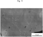
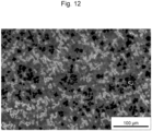
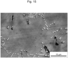
- Figures 10 to 16 show SEM images of the alloys of Examples 1 to 4.
- the alloys of Examples 1 to 4 had a continuous phase 11 (light-colored portion) and a carbide phase 12 (dark-colored portion) dispersed in the continuous phase 11.
- the continuous phase 11 had the FCC structure
- the carbide phase 12 had the NaCl structure.
- the equivalent circle diameters of the carbide phase 12 of the alloys of Examples 1 to 4 were each 50 ⁇ m or less, which was smaller than the average equivalent circle diameter of the carbide phase 22 (dark-colored portion in Figure 8 ) in the WC-Co cemented carbide of the Comparative Example.
- a test piece of a predetermined shape was cut out from the alloy mass of each Example, and its hardness at 700°C was measured. Specifically, using a high-temperature micro Vickers hardness testing system (AVK-HF) manufactured by Mitutoyo Corporation, a diamond indenter was pressed into each test piece heated to 700°C with a load of 5 kg for 30 seconds, and the diagonal length of the indentation was measured. The measurement was carried out ten times, and the hardness of the alloy of each Example was calculated from the average value of the eight measured values, excluding the maximum and minimum values. Similarly, the hardness at 700°C of the WC-Co cemented carbide of the Comparative Example was measured. Table 3 shows the results. [Table 3] Vickers hardness [HV] Example 1 423 Example 2 465 Example 3 358 Example 4 373 Comparative Example 276
- test piece of a predetermined shape was cut out from the alloy mass of each Example. Each test piece was irradiated with a laser beam under the conditions described below to melt and solidify. The test piece of the Comparative Example was also irradiated with a laser beam in the same manner to melt and solidify.
Landscapes
- Chemical & Material Sciences (AREA)
- Engineering & Computer Science (AREA)
- Materials Engineering (AREA)
- Organic Chemistry (AREA)
- Metallurgy (AREA)
- Mechanical Engineering (AREA)
- Manufacturing & Machinery (AREA)
- Structural Engineering (AREA)
- Composite Materials (AREA)
- Civil Engineering (AREA)
- Ceramic Engineering (AREA)
- Physics & Mathematics (AREA)
- Plasma & Fusion (AREA)
- Chemical Kinetics & Catalysis (AREA)
- Powder Metallurgy (AREA)
Applications Claiming Priority (2)
| Application Number | Priority Date | Filing Date | Title |
|---|---|---|---|
| JP2022075773 | 2022-05-02 | ||
| PCT/JP2023/017075 WO2023214567A1 (fr) | 2022-05-02 | 2023-05-01 | Alliage, poudre d'alliage, élément en alliage et élément composite |
Publications (2)
| Publication Number | Publication Date |
|---|---|
| EP4506478A1 true EP4506478A1 (fr) | 2025-02-12 |
| EP4506478A4 EP4506478A4 (fr) | 2025-08-13 |
Family
ID=88646518
Family Applications (1)
| Application Number | Title | Priority Date | Filing Date |
|---|---|---|---|
| EP23799496.7A Pending EP4506478A4 (fr) | 2022-05-02 | 2023-05-01 | Alliage, poudre d'alliage, élément en alliage et élément composite |
Country Status (4)
| Country | Link |
|---|---|
| US (1) | US20250154629A1 (fr) |
| EP (1) | EP4506478A4 (fr) |
| JP (1) | JP7670237B2 (fr) |
| WO (1) | WO2023214567A1 (fr) |
Family Cites Families (12)
| Publication number | Priority date | Publication date | Assignee | Title |
|---|---|---|---|---|
| FR2899240B1 (fr) * | 2006-03-31 | 2008-06-27 | Snecma Sa | Alliage a base de nickel |
| JP5526223B2 (ja) * | 2010-03-29 | 2014-06-18 | 株式会社日立製作所 | Ni基合金、並びにそれを用いたガスタービン動翼及び静翼 |
| US8800848B2 (en) * | 2011-08-31 | 2014-08-12 | Kennametal Inc. | Methods of forming wear resistant layers on metallic surfaces |
| KR101508696B1 (ko) | 2014-11-20 | 2015-04-07 | 남정우 | 초경합금 절삭 공구의 제조 방법 및 이에 의해 제조된 절삭 공구 |
| JP6620029B2 (ja) * | 2015-03-31 | 2019-12-11 | 山陽特殊製鋼株式会社 | 球状粒子からなる金属粉末 |
| JP6519961B2 (ja) * | 2017-09-07 | 2019-05-29 | 日立金属株式会社 | 積層造形用Ni基耐食合金粉末、この粉末を用いた積層造形品と半導体製造装置用部材の製造方法 |
| CN107774997B (zh) * | 2017-10-23 | 2021-02-05 | 江西瑞曼增材科技有限公司 | 一种镍基定向高温合金激光定向增材方法 |
| JP6970438B2 (ja) * | 2018-01-31 | 2021-11-24 | 国立研究開発法人物質・材料研究機構 | Ni基超合金 |
| WO2020086971A1 (fr) * | 2018-10-26 | 2020-04-30 | Oerlikon Metco (Us) Inc. | Alliages à base de nickel résistants à la corrosion et à l'usure |
| WO2020179766A1 (fr) * | 2019-03-04 | 2020-09-10 | 日立金属株式会社 | Article fabriqué de manière additive comprenant un élément en alliage à base de ni, procédé de fabrication d'un élément en alliage à base de ni, et produit utilisant un élément en alliage à base de ni |
| JP6839313B1 (ja) | 2020-02-18 | 2021-03-03 | Dxyz株式会社 | 顔認証方法、プログラム、記録媒体および顔認証システム |
| JP7176661B2 (ja) | 2020-03-31 | 2022-11-22 | 日立金属株式会社 | 合金、合金粉末、合金部材および複合部材 |
-
2023
- 2023-05-01 EP EP23799496.7A patent/EP4506478A4/fr active Pending
- 2023-05-01 US US18/861,977 patent/US20250154629A1/en active Pending
- 2023-05-01 WO PCT/JP2023/017075 patent/WO2023214567A1/fr not_active Ceased
- 2023-05-01 JP JP2024519225A patent/JP7670237B2/ja active Active
Also Published As
| Publication number | Publication date |
|---|---|
| EP4506478A4 (fr) | 2025-08-13 |
| WO2023214567A1 (fr) | 2023-11-09 |
| JPWO2023214567A1 (fr) | 2023-11-09 |
| JP7670237B2 (ja) | 2025-04-30 |
| US20250154629A1 (en) | 2025-05-15 |
Similar Documents
| Publication | Publication Date | Title |
|---|---|---|
| KR102722473B1 (ko) | 알루미늄 합금 부품 제조 공정 | |
| US12134127B2 (en) | Composite member | |
| Freitas et al. | Microstructural characterization and wear resistance of boride-reinforced steel coatings produced by Selective Laser Melting (SLM) | |
| JP7006852B2 (ja) | Wc系超硬合金部材およびwc系超硬合金部材の製造方法 | |
| JP7018603B2 (ja) | クラッド層の製造方法 | |
| EP3950177B1 (fr) | Alliage à base de ni, poudre d'alliage à base de ni, élément d'alliage à base de ni et produit comprenant l'élément d'alliage à base de ni | |
| CN113412172A (zh) | 制造铝合金零件的方法 | |
| US20230191488A1 (en) | Method for producing an aluminium alloy part | |
| CN117396290A (zh) | 采用含有预热的增材制造技术制备铝合金零件的方法 | |
| JP7103548B2 (ja) | Ni-Cr-Mo系合金部材、Ni-Cr-Mo系合金粉末、および、複合部材 | |
| JP7848608B2 (ja) | 溶融凝固成形用Fe基合金及び金属粉末 | |
| EP3950992B1 (fr) | Composition d'alliage, procédé de production de composition d'alliage, et matrice | |
| EP4506478A1 (fr) | Alliage, poudre d'alliage, élément en alliage et élément composite | |
| JP7673810B2 (ja) | 複合材及び複合材の製造方法並びに金型 | |
| JP2024111335A (ja) | スパッタリングターゲット及びその製造方法 | |
| KR20230046239A (ko) | 용융-고화 성형용 Fe계 합금 및 금속 분말 | |
| KR20220031447A (ko) | 코팅체 및 코팅체 제조방법 |
Legal Events
| Date | Code | Title | Description |
|---|---|---|---|
| STAA | Information on the status of an ep patent application or granted ep patent |
Free format text: STATUS: THE INTERNATIONAL PUBLICATION HAS BEEN MADE |
|
| PUAI | Public reference made under article 153(3) epc to a published international application that has entered the european phase |
Free format text: ORIGINAL CODE: 0009012 |
|
| STAA | Information on the status of an ep patent application or granted ep patent |
Free format text: STATUS: REQUEST FOR EXAMINATION WAS MADE |
|
| 17P | Request for examination filed |
Effective date: 20241108 |
|
| AK | Designated contracting states |
Kind code of ref document: A1 Designated state(s): AL AT BE BG CH CY CZ DE DK EE ES FI FR GB GR HR HU IE IS IT LI LT LU LV MC ME MK MT NL NO PL PT RO RS SE SI SK SM TR |
|
| DAV | Request for validation of the european patent (deleted) | ||
| DAX | Request for extension of the european patent (deleted) | ||
| A4 | Supplementary search report drawn up and despatched |
Effective date: 20250716 |
|
| RIC1 | Information provided on ipc code assigned before grant |
Ipc: C22C 19/05 20060101AFI20250710BHEP Ipc: B23K 35/30 20060101ALI20250710BHEP Ipc: B33Y 80/00 20150101ALI20250710BHEP Ipc: B33Y 70/00 20200101ALI20250710BHEP Ipc: B22F 10/28 20210101ALI20250710BHEP Ipc: B22F 1/00 20220101ALI20250710BHEP Ipc: B22F 1/05 20220101ALI20250710BHEP Ipc: B33Y 70/10 20200101ALI20250710BHEP Ipc: B22F 1/148 20220101ALI20250710BHEP Ipc: B22F 10/25 20210101ALI20250710BHEP Ipc: B33Y 10/00 20150101ALI20250710BHEP Ipc: C22C 1/04 20230101ALI20250710BHEP Ipc: C22C 1/05 20230101ALI20250710BHEP Ipc: C22C 1/10 20230101ALI20250710BHEP Ipc: C22C 29/06 20060101ALI20250710BHEP Ipc: C22C 32/00 20060101ALI20250710BHEP Ipc: C22C 30/00 20060101ALN20250710BHEP Ipc: B22F 1/06 20220101ALN20250710BHEP |