EP4506528A1 - Exzentrische laufrolle und hardware-anordnung zum schliessen von öffnungen mit glasscheiben - Google Patents
Exzentrische laufrolle und hardware-anordnung zum schliessen von öffnungen mit glasscheiben Download PDFInfo
- Publication number
- EP4506528A1 EP4506528A1 EP23020373.9A EP23020373A EP4506528A1 EP 4506528 A1 EP4506528 A1 EP 4506528A1 EP 23020373 A EP23020373 A EP 23020373A EP 4506528 A1 EP4506528 A1 EP 4506528A1
- Authority
- EP
- European Patent Office
- Prior art keywords
- eccentric
- pulley
- hole
- fastened
- hardware
- Prior art date
- Legal status (The legal status is an assumption and is not a legal conclusion. Google has not performed a legal analysis and makes no representation as to the accuracy of the status listed.)
- Withdrawn
Links
Images





Classifications
-
- E—FIXED CONSTRUCTIONS
- E05—LOCKS; KEYS; WINDOW OR DOOR FITTINGS; SAFES
- E05D—HINGES OR SUSPENSION DEVICES FOR DOORS, WINDOWS OR WINGS
- E05D15/00—Suspension arrangements for wings
- E05D15/06—Suspension arrangements for wings for wings sliding horizontally more or less in their own plane
- E05D15/0621—Details, e.g. suspension or supporting guides
- E05D15/0626—Details, e.g. suspension or supporting guides for wings suspended at the top
- E05D15/063—Details, e.g. suspension or supporting guides for wings suspended at the top on wheels with fixed axis
-
- E—FIXED CONSTRUCTIONS
- E05—LOCKS; KEYS; WINDOW OR DOOR FITTINGS; SAFES
- E05D—HINGES OR SUSPENSION DEVICES FOR DOORS, WINDOWS OR WINGS
- E05D15/00—Suspension arrangements for wings
- E05D15/06—Suspension arrangements for wings for wings sliding horizontally more or less in their own plane
- E05D15/0621—Details, e.g. suspension or supporting guides
- E05D15/0626—Details, e.g. suspension or supporting guides for wings suspended at the top
- E05D15/063—Details, e.g. suspension or supporting guides for wings suspended at the top on wheels with fixed axis
- E05D15/0634—Details, e.g. suspension or supporting guides for wings suspended at the top on wheels with fixed axis with height adjustment
-
- E—FIXED CONSTRUCTIONS
- E05—LOCKS; KEYS; WINDOW OR DOOR FITTINGS; SAFES
- E05D—HINGES OR SUSPENSION DEVICES FOR DOORS, WINDOWS OR WINGS
- E05D15/00—Suspension arrangements for wings
- E05D15/06—Suspension arrangements for wings for wings sliding horizontally more or less in their own plane
- E05D15/0621—Details, e.g. suspension or supporting guides
- E05D15/0626—Details, e.g. suspension or supporting guides for wings suspended at the top
- E05D15/0652—Tracks
-
- E—FIXED CONSTRUCTIONS
- E05—LOCKS; KEYS; WINDOW OR DOOR FITTINGS; SAFES
- E05Y—INDEXING SCHEME ASSOCIATED WITH SUBCLASSES E05D AND E05F, RELATING TO CONSTRUCTION ELEMENTS, ELECTRIC CONTROL, POWER SUPPLY, POWER SIGNAL OR TRANSMISSION, USER INTERFACES, MOUNTING OR COUPLING, DETAILS, ACCESSORIES, AUXILIARY OPERATIONS NOT OTHERWISE PROVIDED FOR, APPLICATION THEREOF
- E05Y2201/00—Constructional elements; Accessories therefor
- E05Y2201/60—Suspension or transmission members; Accessories therefor
- E05Y2201/622—Suspension or transmission members elements
- E05Y2201/688—Rollers
-
- E—FIXED CONSTRUCTIONS
- E05—LOCKS; KEYS; WINDOW OR DOOR FITTINGS; SAFES
- E05Y—INDEXING SCHEME ASSOCIATED WITH SUBCLASSES E05D AND E05F, RELATING TO CONSTRUCTION ELEMENTS, ELECTRIC CONTROL, POWER SUPPLY, POWER SIGNAL OR TRANSMISSION, USER INTERFACES, MOUNTING OR COUPLING, DETAILS, ACCESSORIES, AUXILIARY OPERATIONS NOT OTHERWISE PROVIDED FOR, APPLICATION THEREOF
- E05Y2600/00—Mounting or coupling arrangements for elements provided for in this subclass
- E05Y2600/10—Adjustable
- E05Y2600/12—Adjustable by manual operation
-
- E—FIXED CONSTRUCTIONS
- E05—LOCKS; KEYS; WINDOW OR DOOR FITTINGS; SAFES
- E05Y—INDEXING SCHEME ASSOCIATED WITH SUBCLASSES E05D AND E05F, RELATING TO CONSTRUCTION ELEMENTS, ELECTRIC CONTROL, POWER SUPPLY, POWER SIGNAL OR TRANSMISSION, USER INTERFACES, MOUNTING OR COUPLING, DETAILS, ACCESSORIES, AUXILIARY OPERATIONS NOT OTHERWISE PROVIDED FOR, APPLICATION THEREOF
- E05Y2600/00—Mounting or coupling arrangements for elements provided for in this subclass
- E05Y2600/60—Mounting or coupling members; Accessories therefor
- E05Y2600/622—Dowels; Pins
-
- E—FIXED CONSTRUCTIONS
- E05—LOCKS; KEYS; WINDOW OR DOOR FITTINGS; SAFES
- E05Y—INDEXING SCHEME ASSOCIATED WITH SUBCLASSES E05D AND E05F, RELATING TO CONSTRUCTION ELEMENTS, ELECTRIC CONTROL, POWER SUPPLY, POWER SIGNAL OR TRANSMISSION, USER INTERFACES, MOUNTING OR COUPLING, DETAILS, ACCESSORIES, AUXILIARY OPERATIONS NOT OTHERWISE PROVIDED FOR, APPLICATION THEREOF
- E05Y2600/00—Mounting or coupling arrangements for elements provided for in this subclass
- E05Y2600/60—Mounting or coupling members; Accessories therefor
- E05Y2600/624—Nuts
-
- E—FIXED CONSTRUCTIONS
- E05—LOCKS; KEYS; WINDOW OR DOOR FITTINGS; SAFES
- E05Y—INDEXING SCHEME ASSOCIATED WITH SUBCLASSES E05D AND E05F, RELATING TO CONSTRUCTION ELEMENTS, ELECTRIC CONTROL, POWER SUPPLY, POWER SIGNAL OR TRANSMISSION, USER INTERFACES, MOUNTING OR COUPLING, DETAILS, ACCESSORIES, AUXILIARY OPERATIONS NOT OTHERWISE PROVIDED FOR, APPLICATION THEREOF
- E05Y2600/00—Mounting or coupling arrangements for elements provided for in this subclass
- E05Y2600/60—Mounting or coupling members; Accessories therefor
- E05Y2600/626—Plates or brackets
-
- E—FIXED CONSTRUCTIONS
- E05—LOCKS; KEYS; WINDOW OR DOOR FITTINGS; SAFES
- E05Y—INDEXING SCHEME ASSOCIATED WITH SUBCLASSES E05D AND E05F, RELATING TO CONSTRUCTION ELEMENTS, ELECTRIC CONTROL, POWER SUPPLY, POWER SIGNAL OR TRANSMISSION, USER INTERFACES, MOUNTING OR COUPLING, DETAILS, ACCESSORIES, AUXILIARY OPERATIONS NOT OTHERWISE PROVIDED FOR, APPLICATION THEREOF
- E05Y2600/00—Mounting or coupling arrangements for elements provided for in this subclass
- E05Y2600/60—Mounting or coupling members; Accessories therefor
- E05Y2600/632—Screws
-
- E—FIXED CONSTRUCTIONS
- E05—LOCKS; KEYS; WINDOW OR DOOR FITTINGS; SAFES
- E05Y—INDEXING SCHEME ASSOCIATED WITH SUBCLASSES E05D AND E05F, RELATING TO CONSTRUCTION ELEMENTS, ELECTRIC CONTROL, POWER SUPPLY, POWER SIGNAL OR TRANSMISSION, USER INTERFACES, MOUNTING OR COUPLING, DETAILS, ACCESSORIES, AUXILIARY OPERATIONS NOT OTHERWISE PROVIDED FOR, APPLICATION THEREOF
- E05Y2900/00—Application of doors, windows, wings or fittings thereof
- E05Y2900/10—Application of doors, windows, wings or fittings thereof for buildings or parts thereof
- E05Y2900/114—Application of doors, windows, wings or fittings thereof for buildings or parts thereof for showers
-
- E—FIXED CONSTRUCTIONS
- E05—LOCKS; KEYS; WINDOW OR DOOR FITTINGS; SAFES
- E05Y—INDEXING SCHEME ASSOCIATED WITH SUBCLASSES E05D AND E05F, RELATING TO CONSTRUCTION ELEMENTS, ELECTRIC CONTROL, POWER SUPPLY, POWER SIGNAL OR TRANSMISSION, USER INTERFACES, MOUNTING OR COUPLING, DETAILS, ACCESSORIES, AUXILIARY OPERATIONS NOT OTHERWISE PROVIDED FOR, APPLICATION THEREOF
- E05Y2900/00—Application of doors, windows, wings or fittings thereof
- E05Y2900/10—Application of doors, windows, wings or fittings thereof for buildings or parts thereof
- E05Y2900/13—Type of wing
- E05Y2900/132—Doors
Definitions
- the present invention patent concerns the eccentric pulley and hardware assembly for closing spans with glass panels such as doors, boxes and room partitions.
- the eccentric pulley was developed with the purpose of allowing a greater amplitude of regulation during the assembly of tempered or laminated glass panels, reaching in a first version, an adjustment range of 16 mm, that is, between -8 mm and +8 mm, and, in a second version, said eccentric pulley of apparent use, it becomes possible to regulate 8 mm, that is, between -4 mm and +4 mm, allowing optimization of installation and ease of assembly of the closing of spans with fastened and movable glass panels, especially with respect to the leveling adjustment of said panels in relation to the floor and walls.
- Eccentric pulleys are accessories assembled on the upper edge of the movable panels assisting both in the sliding of said glass panels on the upper and lower profiles, and in the adjustment of the plumb of the glasses.
- the conventional pulleys comprise a set of parts assembled in such a way as to compose eccentric axes that, by torquing these parts to each other, allows the adjustment of height of the panels to obtain the leveling of glass plates in relation to the floor.
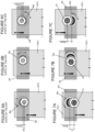
- the current eccentric pulleys have varied configurations, however, in general, they reach a range of regulation of 4 mm at most, that is, between -2 mm and +2 mm (6A, 6B and 6C), which in many cases is not enough to achieve a perfect fit of the panels in relation to the floor and side walls.
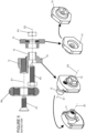
- a conventional pulley (RE) model cited only as an example for better understanding (see Figs. 1 and 2 of the State of the Art), is one whose basic parts - support and support cover - are made with brass parts, including the bushing, while the threaded spindle is made in stainless steel or other.
- FIGS 1 and 2 represent, by way of example, a conventional model where the eccentric pulley (RE) comprises a caster (Rd) made of polyacetal or other similar material in whose center is poured and pierced by a threaded screw (P1) assembled on the axle (E1) that also passes through a brass support (Sp1) and an eccentric brass bushing (Be) arranged on the axle (E2) with a distance (x) of 2 mm from the axle (E1), a bushing that is fitted in a hole (O1) of the movable glass panel (PV1) and that receives the juxtaposition of thrust washer (A1). The entire assembly is fastened by nut (P3).
- the eccentric pulley comprises a caster (Rd) made of polyacetal or other similar material in whose center is poured and pierced by a threaded screw (P1) assembled on the axle (E1) that also passes through a brass support (Sp1) and an eccentric brass bushing (Be) arranged on the axle (E2) with
- the distance between the axles (E1) and (E2) of the conventional eccentric pulley models generally have a distance (x) of at most 2 mm, that is, the alignment adjustment in this conventional eccentric pulley model is 4 mm, that is, -2 mm (down) or + 2 mm (up) ( figures 6A, 6B and 6C ), a fact that limits the proper adjustment of the movable glass panels (PV1), and may even, due to the structural deformations of the civil construction, not provide the necessary adjustment and make it impossible to properly level, leaving exposed spans between the glass panels and the ground and also in relation to the walls, compromising the aesthetics as well as the tightness and sealing.
- the eccentric pulley of the apparent type presents itself in such a way as to be not only compatible and harmonious aesthetic look with the complementary hardware assembly, giving a more elegant and modern look to the closing of spans with glass panels, allows adjustment.
- This visual compatibility results in a lighter and more discreet structure, which complements the aesthetics of glass panels.
- the present invention is expected to offer an efficient and aesthetically pleasing solution for closing spans with glass panels.
- the other components that constitute the complementary hardware of span closures by means of glass panels are the support profiles of the eccentric pulleys and also the fastening components of the support rail, the end stop and the lower slide guide of the movable glass panel.
- these components are made, as a rule, to complete the characteristics of the supporting pulleys of the panels, in order to harmonize the assemblies.
- BR MU 8100702-7 which features an eccentric pulley equipped with a bearing for use in sliding doors and other elements consists of a sliding element equipped with an axle, intermediate body provided with front and rear fastening bushings and adjustment element equipped with a screw, and the sliding element is formed by a cylindrical body with a core and internal bearing, has a screw that allows it to be fastened to the front bushing and positioned in a displaced manner in relation to the central point of this face of the body, at the rear is positioned the rear bushing, perfectly centered, the eccentricity of the front bushing allows the sliding element to remain positioned at the front thereof and in the rail channel, the intermediate body is supported on the surface of door, the rear bushing penetrates into the hole to receive the regulating element, placed at the back of door, the screw is introduced into the hole and the rear bushing, this form of installation allows the tight
- Document No. BR MU 8303182-0 is a typical example of conventional eccentric pulley as defined in Figs. 1 and 2 , that is, it presents an eccentric pulley with self-lubricating bearing or bushing comprising a pulley composed of a brass or similar axle coated with plastic or similar washers lining the glass fitting raceway and a self-lubricating bushing on the front of the pulley.
- Document No. CN 214246999 discloses an outer double sliding door, an inner sliding door, a guide rail, and a rolling guide rail, adjustable anti-rise pulley blocks that are disposed on both sides of the top of outer sliding door, respectively, each adjustable anti-rise pulley block comprising an adjustable anti-rise hook disposed on both sides of the top of outer sliding door, respectively.
- Document No. CN 103590717A features a bathroom boxing consisting of a wall base, a base and glass doors.
- the glass doors include a movable door and a fastened door; a sliding band is disposed horizontally at the top of the assembly and two upper pulleys and a lower pulley are attached to the upper end of the movable door; a plastic pulley is disposed in the middle of each pulley; strips are embedded in the upper surface and the lower surface of the sliding strip; the sliding strip is located between the upper pulleys and the lower pulley; the base comprises a lower guide rail and a side rail, and the upper surface of the lower guide rail is free of sliding grooves.
- the advantage of the eccentric pulley (10) ( Figs. 3 and 4 ) of the first version presented in this application consists in the fact that, conceptually, it maintains practically the same dimensions as conventional pulleys, however it enables a greater range of adjustment in relation to the usual market models since it presents a main support (10) whose projecting pin (11), which secures the caster or bearing (Rd) by means of a spindle (P1) and which is arranged on the Axle (E1), is maintained at a distance (y) of at least 16 mm in relation to the projecting pin (12) assembled on the axle (E3), which runs through the hole (O) of the movable glass panel (PV1).
- a cover (13) that fits on the outside of the projecting pin (12) and is fastened to it by means of the screw (P2) and respective nut (P3). Therefore, the distance of at least 16 mm between the axles (E1) and (E3) allows the support (10) with the caster (Rd) to rotate in relation to the cover (13) supporting the movable glass panel (PV1) in a range between -8 mm to +8 mm (see figures 7A, 7B and 7C ) with a wheelbase of 16 mm (y), considerably increasing the possibility of adjustment and alignment of said glass panel in relation to the floor and walls.
- Another advantage of the model of first eccentric pulley version lies in the fact that the support part and the support cover of the glass panel are made of engineering polymer, for example nylon with its reinforcing loads such as fiberglass, tungsten and other elements, in addition to dispensing with the intermediate insulating ring, reducing costs without, however, losing the mechanical strength in relation to the weight of glass panels, since the threaded spindles arranged longitudinally in the eccentric pulley act as mechanical reinforcing axles.
- the bushing where the caster is arranged, is made of sintered bronze that gives greater durability to the product, as well as a smoother movement, especially in environments with high humidity, especially when compared to the pulley with carbon steel bearing or with sliding systems, thus bringing a solution with real improvements for buyers who will have lower maintenance costs, as well as being able to have a quality product for much longer, in addition to having a safer movement, since it is smooth.
- Another advantage consists in the fact of the oblong configuration of the support, as well as the predictability of an individualized hole intended for assembly an adjustment axle, enabling the transfer of vertical load from the caster to said axle, preventing it from being overloaded with the weight derived from the glass plates.
- Another substantial advantage of the new configuration of the eccentric pulley is that it may expand its application in the glass market, such as, in addition to the traditional use in the assembly of bathroom boxes, the same, due to this range of adjustment achieved and superior mechanical strength, can be used in glazing or closures of balconies, room partitions and other applications.
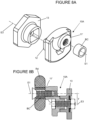
- the constructive variation of the eccentric pulley developed to be of the apparent type and respective innovative hardware assembly allows, in addition to a safe and smooth sliding of the glass panels, while minimizing the amount of structuring required, allows the glass panels to be adjusted in a setting range of 8 mm (w) between the fastened axle (E1) and the eccentric axle (E4) ( Fig. 9A, 9B and other figures), that is, an adjustment from -4 mm to + 4 mm, also ensuring a bold and sophisticated look to the hardware assembly, providing a more pleasant and aesthetically attractive user experience.
- Another innovation of the present invention refers to the model of support rail of the apparent eccentric pulley, a rail in extruded aluminum that adopts a shape of little thickness and little height, that is, visually compatible with the lightness of the hardware assembly, but, at the same time, is robust and capable of adopting varied configurations to receive the support of the eccentric pulley, with a section suitable for said support rail, in order to prevent said support of the pulley from involuntarily escaping from the rail, that is, the new model of rail ensures the safety of sliding of the apparent eccentric pulley, dispensing with conventional safety locks and accessories.
- Innovation also has a stopper for the movable glass panel that comprises a guide part with two oblong and hollow holes, one for the passage of support rail and another for the assembly of a resilient part, such as rubber or equivalent.
- a stopper for the movable glass panel that comprises a guide part with two oblong and hollow holes, one for the passage of support rail and another for the assembly of a resilient part, such as rubber or equivalent.
- a lower guide for displacement of the movable glass panel is also provided, which is formed by two basic parts, one of them to be fastened to the floor and another fitted on the previous one, allowing better adjustment and positioning of this guide, facilitating the final assembly of the span closure.
- the eccentric pulley ( Figs. 3, 4 and 5 ) comprises a main support (10) with projecting pin (11) that secures the caster or bearing (Rd) by means of a spindle (P1) and that is arranged on the Axle (E1) at a distance (y) of at least 16 mm in relation to the projecting pin (12) assembled on the axle (E3), responsible for being fitted in the hole (O) of the movable glass panel (PV1) together with a cover (13), both pin (12) and cover (13) being fastened to each other by screw (P2) and nut (P3).
- the distance (y) of at least 16 mm between the axes (E1) and (E3) allows the support (10) with the caster (Rd) to rotate with respect to the cover (13) supporting the movable glass panel (PV1) in a range between -8 mm to +8 mm, considerably expanding the possibility of adjustment and alignment of said movable glass panel (PV1) with respect to the floor and side walls (see figures 7A, 7B and 7C ).
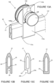
- the caster comprising a pulley (108), divided into three parts, being a cover (108a) with central hole (108a1) for accommodation of a bronze bushing (BC) and at least three tubular projections (108a2) distributed radially with respect to the hole (108a1), each projection (108a2) being provided with hole (108a3) for corresponding fitting of pins (108c1) projecting from the inner face of the opposite cover (108c).
- a pulley (108) divided into three parts, being a cover (108a) with central hole (108a1) for accommodation of a bronze bushing (BC) and at least three tubular projections (108a2) distributed radially with respect to the hole (108a1), each projection (108a2) being provided with hole (108a3) for corresponding fitting of pins (108c1) projecting from the inner face of the opposite cover (108c).
- bearing (108b) Between the covers (108a)/(108c) is provided bearing (108b) with sliding channel (108b1), circular recess (
- the distance (w) between the axles (E1) and (E4) is 8 mm, allowing the adjustment of the movable glass panel (PV1) in relation to the floor in an adjustment range between -4 mm and +4 mm.
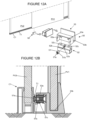
- the support rail (20) of the present invention serves both for assembly the movable glass panel (PV1) and the fastened glass panel (PV2) ( Fig. 10 ).
- the support rail is an aluminum extruded part to the ordinary shape of a centrally cast rectangle, comprising a tapered and rounded upper base (21) capable of accommodating the channel (108b1) of the pulley (108), as well as providing a wall (22) for fastening the assembly hardware (111) of the fastened glass panel (PV1), while the opposite wall (23) of the rail (20) is free and both (22/23) are joined in the lower portion by a base (24), comprising an inverted "U” section comprising a longitudinal channel (25) capable of receiving at least one protruding pin or guide (110c1) from the horizontal branch (110c) of the guide laminar part (110) of the apparent type eccentric pulley (100).
- the lower base (24) presents a projecting tooth (24a) forming a recess (24b) that accommodates in the fold (110d) of the horizontal branch (110c) of the guide laminar piece (110).
- the base (24) is flat and capable of being supported on a smooth horizontal branch (110c) of the guide laminar part (110).
- One of the complementary hardware of the support rail assembly (20) is the assembly and fastening component (30) of the rail next to the walls.
- the fastening component (30) is formed by two parts ( Figs. 10 , 12A and 12B ) being an "L" piece (31), where the branch (31a) is of square section and provided with at least one hollow hole (31b) for passing screw (P5) fastening next to the wall and at least one threaded hole (31c) practiced at the top of said branch (31a).
- the branch (31d) comprises a short blade that serves as a support for the lower base (24) of the support rail (20).
- Said "L” part has a dimension to be fitted fairly in the housing (32a) of the trim part (32) which, in turn, has a hole (32b) in the upper base for the overpass of the fastening screw (P6)
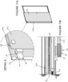
- a stopper (40) ( Fig. 10 and detail A of Fig. 11A and Fig. 11B ) for the glass movable panel (PV1) comprising an ordinarily parallelepipedal guide piece with two oblong and hollow holes, one hole (41) for the passage of the support rail (20) and another hole (42) for the assembly of a resilient part (43), such as rubber or equivalent.
- a lower guide (50) is also provided ( Figs. 12A and 12b ) for displacement of the movable glass panel (PV1), which is formed by three parts, being a key (51), preferably metallic, which has an oblong head (51a) capable of fitting and adjusting the positioning of the lower guide (50) on the side rail (T1) of the lower frame (C1).
- a key (51) preferably metallic, which has an oblong head (51a) capable of fitting and adjusting the positioning of the lower guide (50) on the side rail (T1) of the lower frame (C1).
- Said key (51) also has a quadrangular body (51b) with a threaded hole (51c) capable of sitting in a recess (52a) practiced in the center of the fastening bearing (52), ordinarily parallelepipedal and equipped with a channel (52b) for juxtaposition next to the outer face of the rail (T1) of the frame (C1).
- the upper face of the bearing (52) provides at least two holes (52c) that act as a seating guide for corresponding pins (53a) of the guide (53) with a "U" section (53b) for accommodating the lower end of the glass movable panel (PV1).
Landscapes
- Engineering & Computer Science (AREA)
- Mechanical Engineering (AREA)
- Support Devices For Sliding Doors (AREA)
Priority Applications (2)
| Application Number | Priority Date | Filing Date | Title |
|---|---|---|---|
| EP23020373.9A EP4506528A1 (de) | 2023-08-09 | 2023-08-09 | Exzentrische laufrolle und hardware-anordnung zum schliessen von öffnungen mit glasscheiben |
| US18/494,325 US20250052101A1 (en) | 2023-08-09 | 2023-10-25 | Eccentric pulley and hardware assembly for closing spans with glass panels |
Applications Claiming Priority (1)
| Application Number | Priority Date | Filing Date | Title |
|---|---|---|---|
| EP23020373.9A EP4506528A1 (de) | 2023-08-09 | 2023-08-09 | Exzentrische laufrolle und hardware-anordnung zum schliessen von öffnungen mit glasscheiben |
Publications (1)
| Publication Number | Publication Date |
|---|---|
| EP4506528A1 true EP4506528A1 (de) | 2025-02-12 |
Family
ID=87567490
Family Applications (1)
| Application Number | Title | Priority Date | Filing Date |
|---|---|---|---|
| EP23020373.9A Withdrawn EP4506528A1 (de) | 2023-08-09 | 2023-08-09 | Exzentrische laufrolle und hardware-anordnung zum schliessen von öffnungen mit glasscheiben |
Country Status (2)
| Country | Link |
|---|---|
| US (1) | US20250052101A1 (de) |
| EP (1) | EP4506528A1 (de) |
Families Citing this family (1)
| Publication number | Priority date | Publication date | Assignee | Title |
|---|---|---|---|---|
| CN117108155B (zh) * | 2023-09-20 | 2025-09-23 | 中山薇宝卫浴有限公司 | 一种淋浴房用调节型滑轮结构 |
Citations (7)
| Publication number | Priority date | Publication date | Assignee | Title |
|---|---|---|---|---|
| BR8100702U (pt) | 2001-04-23 | 2002-12-24 | Alclean Extrusao De Metais Ltd | Roldana excêntrica dotada de rolamento para uso de deslizamento de portas e outros elementos |
| KR200313460Y1 (ko) * | 2003-02-10 | 2003-05-14 | 곽인학 | 행거 도어용 높이조절식 로울러부착형 브라켓 |
| BR8303182U (pt) | 2003-12-16 | 2005-08-09 | Ronald Jose Paciullo | Configuração aplicada em roldana excêntrica com rolamento ou bucha auto lubrificante |
| KR200394260Y1 (ko) * | 2005-06-20 | 2005-08-31 | 박종문 | 행거도어의 높낮이 조정용 도어행거 |
| CN103590717A (zh) | 2013-10-23 | 2014-02-19 | 平湖乐优卫浴有限公司 | 一种有静音条的淋浴房 |
| BR202013005023U2 (pt) * | 2013-03-01 | 2015-06-09 | Fernando Elerbrock | Disposição introduzida em roldana com regulagem de altura para nivelamento de produtos corrediços sobre trilhos |
| CN214246999U (zh) | 2020-10-15 | 2021-09-21 | 佛山市南海斯唯特卫浴有限公司 | 一种无框易装带可调节止动器双移门淋浴房 |
Family Cites Families (12)
| Publication number | Priority date | Publication date | Assignee | Title |
|---|---|---|---|---|
| GB990057A (en) * | 1961-08-04 | 1965-04-22 | Centor Products Pty Ltd | Improvements in and connected with carriers for sliding doors |
| CH442067A (de) * | 1965-04-23 | 1967-08-15 | Idealheim Ag | Schiebetüre |
| US3469892A (en) * | 1968-06-03 | 1969-09-30 | Watsco Inc | Shielded-bearing roller for suspension devices |
| DE3429053C1 (de) * | 1984-08-07 | 1986-02-06 | Heinz Georg Hünibach Thun Baus | Duschabtrennung |
| DE3605770A1 (de) * | 1986-02-22 | 1987-08-27 | Heinz Georg Baus | Trennwand, insbesondere fuer eine runddusche |
| DE3616242C1 (en) * | 1986-05-14 | 1988-01-21 | Hueppe Gmbh | Adjustable supporting-roller and running-roller device on sliding doors |
| EP1916372B1 (de) * | 2006-10-23 | 2016-12-28 | Hawa Ag | Vorrichtung zum Halten von Platten und Trennelement |
| US20130042534A1 (en) * | 2011-08-16 | 2013-02-21 | Doron Polus | Modular sliding door system |
| CN103255972B (zh) * | 2013-05-13 | 2015-12-02 | 周裕佳 | 淋浴门高度调节装置 |
| ES1191083Y (es) * | 2017-08-02 | 2017-11-29 | Klein Iberica S A U | Dispositivo de sujecion de hojas de vidrio para puertas correderas |
| US11466495B2 (en) * | 2020-03-01 | 2022-10-11 | Maax Bath Inc. | Apparatuses for installing glass shower doors |
| CN213980388U (zh) * | 2020-07-16 | 2021-08-17 | 中山市瑞莎卫浴科技有限公司 | 一种淋浴门滑轮组件 |
-
2023
- 2023-08-09 EP EP23020373.9A patent/EP4506528A1/de not_active Withdrawn
- 2023-10-25 US US18/494,325 patent/US20250052101A1/en not_active Abandoned
Patent Citations (7)
| Publication number | Priority date | Publication date | Assignee | Title |
|---|---|---|---|---|
| BR8100702U (pt) | 2001-04-23 | 2002-12-24 | Alclean Extrusao De Metais Ltd | Roldana excêntrica dotada de rolamento para uso de deslizamento de portas e outros elementos |
| KR200313460Y1 (ko) * | 2003-02-10 | 2003-05-14 | 곽인학 | 행거 도어용 높이조절식 로울러부착형 브라켓 |
| BR8303182U (pt) | 2003-12-16 | 2005-08-09 | Ronald Jose Paciullo | Configuração aplicada em roldana excêntrica com rolamento ou bucha auto lubrificante |
| KR200394260Y1 (ko) * | 2005-06-20 | 2005-08-31 | 박종문 | 행거도어의 높낮이 조정용 도어행거 |
| BR202013005023U2 (pt) * | 2013-03-01 | 2015-06-09 | Fernando Elerbrock | Disposição introduzida em roldana com regulagem de altura para nivelamento de produtos corrediços sobre trilhos |
| CN103590717A (zh) | 2013-10-23 | 2014-02-19 | 平湖乐优卫浴有限公司 | 一种有静音条的淋浴房 |
| CN214246999U (zh) | 2020-10-15 | 2021-09-21 | 佛山市南海斯唯特卫浴有限公司 | 一种无框易装带可调节止动器双移门淋浴房 |
Also Published As
| Publication number | Publication date |
|---|---|
| US20250052101A1 (en) | 2025-02-13 |
Similar Documents
| Publication | Publication Date | Title |
|---|---|---|
| US5694665A (en) | Adjustable hinge | |
| EP1061221B1 (de) | Scharnier für einen zu öffnenden Tür- oder Fensterrahmen | |
| US5755011A (en) | Adjustable hinge | |
| US20250052101A1 (en) | Eccentric pulley and hardware assembly for closing spans with glass panels | |
| EP1672155B1 (de) | Verstellbares Scharnier für Türen und Fenster | |
| US5581947A (en) | Vehicle door assembly | |
| EP0992647B1 (de) | Verstellbares Scharnier für Türrahmen | |
| US4655025A (en) | Edge rail for a window pane, in particular an all-glass door | |
| US5042554A (en) | Support or guide roller device | |
| US3285324A (en) | Bi-fold hardware for foldable doors | |
| AU2006298879B2 (en) | Mechanism for the instalment of a door or other similar closure having a rotational-sliding movement | |
| EP1606485A1 (de) | Beschlag | |
| US3134134A (en) | Hinge assembly | |
| US20100147042A1 (en) | Convenient sliding glass door intermediate lock system | |
| US2778068A (en) | Window construction | |
| US3599275A (en) | Hinge structure | |
| US3349429A (en) | Hinge | |
| RU2539674C2 (ru) | Механизм для установки двери или другого аналогичного закрывающего устройства с вращательным и поступательным перемещением | |
| CA2638440C (en) | Adjustable hinge for doors and windows | |
| US11952818B2 (en) | Shower door hinge assembly | |
| WO2008111107A2 (en) | Fencing system | |
| TWM592022U (zh) | 隱藏式鉸鏈結構 | |
| GB2264532A (en) | Adjustable hinge having bush with eccentric bore | |
| US891275A (en) | Safe, vault, &c. | |
| JP3255127B2 (ja) | 吊下げ式引戸 |
Legal Events
| Date | Code | Title | Description |
|---|---|---|---|
| PUAI | Public reference made under article 153(3) epc to a published international application that has entered the european phase |
Free format text: ORIGINAL CODE: 0009012 |
|
| STAA | Information on the status of an ep patent application or granted ep patent |
Free format text: STATUS: THE APPLICATION HAS BEEN PUBLISHED |
|
| AK | Designated contracting states |
Kind code of ref document: A1 Designated state(s): AL AT BE BG CH CY CZ DE DK EE ES FI FR GB GR HR HU IE IS IT LI LT LU LV MC ME MK MT NL NO PL PT RO RS SE SI SK SM TR |
|
| STAA | Information on the status of an ep patent application or granted ep patent |
Free format text: STATUS: THE APPLICATION IS DEEMED TO BE WITHDRAWN |
|
| 18D | Application deemed to be withdrawn |
Effective date: 20250813 |