EP4506572A2 - Pompe à vide - Google Patents
Pompe à vide Download PDFInfo
- Publication number
- EP4506572A2 EP4506572A2 EP24220715.7A EP24220715A EP4506572A2 EP 4506572 A2 EP4506572 A2 EP 4506572A2 EP 24220715 A EP24220715 A EP 24220715A EP 4506572 A2 EP4506572 A2 EP 4506572A2
- Authority
- EP
- European Patent Office
- Prior art keywords
- rfid
- vacuum pump
- rfid transponder
- component
- rfid reader
- Prior art date
- Legal status (The legal status is an assumption and is not a legal conclusion. Google has not performed a legal analysis and makes no representation as to the accuracy of the status listed.)
- Pending
Links
Images


Classifications
-
- F—MECHANICAL ENGINEERING; LIGHTING; HEATING; WEAPONS; BLASTING
- F04—POSITIVE - DISPLACEMENT MACHINES FOR LIQUIDS; PUMPS FOR LIQUIDS OR ELASTIC FLUIDS
- F04D—NON-POSITIVE-DISPLACEMENT PUMPS
- F04D27/00—Control, e.g. regulation, of pumps, pumping installations or pumping systems specially adapted for elastic fluids
- F04D27/001—Testing thereof; Determination or simulation of flow characteristics; Stall or surge detection, e.g. condition monitoring
-
- F—MECHANICAL ENGINEERING; LIGHTING; HEATING; WEAPONS; BLASTING
- F04—POSITIVE - DISPLACEMENT MACHINES FOR LIQUIDS; PUMPS FOR LIQUIDS OR ELASTIC FLUIDS
- F04D—NON-POSITIVE-DISPLACEMENT PUMPS
- F04D19/00—Axial-flow pumps
- F04D19/02—Multi-stage pumps
- F04D19/04—Multi-stage pumps specially adapted to the production of a high vacuum, e.g. molecular pumps
- F04D19/042—Turbomolecular vacuum pumps
Definitions
- the invention relates to a vacuum pump with a sensor which is arranged on a component of the vacuum pump and is designed to measure a physical property of this component, as well as a method for operating such a vacuum pump.
- a pyrometer with thermal or photoelectric detectors can be used to measure the temperature of a rotor shaft.
- the emissivity of a measuring surface on the rotor shaft which is detected by the pyrometer, must be known precisely.
- it is usually assumed that such a measurement parameter as the emissivity of the measuring surface does not change during operation of the vacuum pump.
- this assumption may not be correct under the specific operating conditions of the vacuum pump. For example, due to Properties of the gases to be pumped may cause a coating on the surfaces of the vacuum pump to occur, which changes the emissivity of the measuring surface.
- performance characteristics can be used to indirectly measure the temperature of the vacuum pump rotor, in which the rotor temperature is assigned to a specific power consumption of the vacuum pump.
- magnetic-inductive measuring methods can be used to measure the rotor temperature indirectly.
- the known contactless measurement methods for certain physical or chemical properties of vacuum pump components therefore usually require certain assumptions, for example regarding the temporal constancy of known measurement parameters, as explained above.
- the known contactless measurement methods usually require a specific calibration of the vacuum pump before it can be delivered, which can be associated with considerable costs.
- the known contactless measurement methods can be surface-sensitive, and their reliability can depend on the respective operating situation or the current load case of the vacuum pump.
- An object of the invention is to provide a vacuum pump and a method for operating such a vacuum pump, with which a contactless measurement of a predetermined physical or chemical property of a component of the vacuum pump is possible in a reliable manner without complex calibration.
- the vacuum pump comprises a sensor which is arranged on a first component of the vacuum pump and is designed to measure a physical property of the first component, and an RFID transponder which is attached to the first component and is in a communicative connection with the sensor.
- the RFID transponder is a device with a transmitter and receiver for identification which operates in the radio frequency range (RFID).
- the vacuum pump further comprises an RFID reader which is attached to a second component of the vacuum pump, which is different from the first component, at such a distance from the RFID transponder that the RFID reader and the RFID transponder are in a communicative connection.
- the vacuum pump can be, for example, a turbomolecular pump
- the first component can be, for example, a rotor of such a turbomolecular pump.
- the first component can also be another, hard-to-reach component of the vacuum pump that does not rotate.
- the sensor is, for example, a temperature sensor attached to a rotor of a turbomolecular pump, or another sensor such as a gyroscope or a strain gauge.
- the RFID transponder and the RFID reader form an RFID system that identifies the RFID transponder, for example by storing a unique identifier on a microchip of the RFID transponder, which is queried by means of a query signal from the RFID reader after the RFID transponder has been woken up and sent to the RFID reader. This identification ensures that the RFID reader is in a communicative connection with the desired RFID transponder and not with any other device.
- the RFID transponder and the sensor preferably do not require their own energy storage device, such as a battery. Instead, the RFID transponder and the sensor can be supplied with energy using electromagnetic waves emitted by the RFID reader. Signals sent by the RFID reader, for example the query signal mentioned above or other signals, can be received and rectified by the RFID transponder in order to supply the RFID transponder and the sensor with energy using such a rectified signal.
- measured values of the sensor which represent the physical property of the first component, can be transmitted from the sensor to the RFID transponder and from there to the RFID reader, which is also communicatively connected to the RFID transponder.
- the RFID reader can be designed to evaluate the measured values recorded by the sensor and to pass on corresponding information, e.g. regarding the temperature of a rotor of the vacuum pump, to a control device of the vacuum pump.
- the use of the RFID transponder and the RFID reader thus allows wireless transmission or recording of measured values of the physical properties of the first component, for example the temperature of the rotor of the turbomolecular pump.
- Such wireless recording of the sensor's measured values requires little effort, since no individual calibration of the entire system is required, for example before delivery of the vacuum pump.
- the emissivity a measuring surface in a pyrometric temperature measurement.
- the sensor can be pre-calibrated and placed on the first component of the vacuum pump to perform a direct measurement of the physical property of the first component without any further assumptions. This allows an accurate determination of the physical property of the first component.
- the distance between the RFID reader and the RFID transponder is preferably selected such that an electrical oscillating circuit of the RFID transponder can be adapted to a resonance frequency of the RFID communication between the RFID reader and the RFID transponder. If the distance is too large or if the geometry between the RFID transponder and the RFID reader changes, communication between them may no longer be possible.
- the RFID transponder and the RFID reader are arranged adjacent to one another in an interior of the vacuum pump.
- the interior can be located within a housing of the vacuum pump and also preferably comprise the evacuated area of the vacuum pump.
- the RFID reader can therefore be connected to one or more vacuum feedthroughs, which, for example, enable the RFID reader to communicate with a control unit of the vacuum pump and to transmit measured values to it.
- the arrangement of the RFID transponder and the RFID reader in the interior of the vacuum pump enables direct recording of measured values of the physical property of the first component when this is arranged in the interior of the vacuum pump and is possibly not accessible from the outside, i.e. from outside the housing of the vacuum pump.
- the sensor can be integrated into the RFID transponder. Such a combination of the sensor with the RFID transponder requires little installation space and thus allows a flexible arrangement of the RFID transponder with integrated sensor on the first component.
- the sensor and the RFID transponder can be arranged at a distance from one another on the first component. If the sensor detects the temperature of the first component, for example the temperature of a rotor of the vacuum pump, the temperature on the first component at a desired installation position of the sensor can be too high for the RFID transponder to operate. If the sensor is attached to a rotor of a turbomolecular pump, for example, temperatures greater than 85°C can occur at certain points on the rotor, at which it is not possible to operate an RFID transponder with an integrated sensor. In such a case, only the sensor can be attached at the desired installation position, while the RFID transponder can be attached at a position where temperatures that are too high for its operation are not expected. If the sensor and the RFID transponder are arranged at a distance from one another on the first component, they can communicate with each other either wirelessly or via cable.
- the RFID transponder can also be designed as a printed circuit board (PCB board) that is embedded in the first component.
- PCB board printed circuit board
- the components of the RFID transponder can be integrated into the material of the printed circuit board and thus protected, for example, from high centrifugal forces if the first component is the rotor of the vacuum pump.
- the components of the RFID transponder can first be applied to the printed circuit board using standardized manufacturing processes and then sealed with a suitable potting compound, for example based on a Two-component epoxy. This provides additional protection for the components against the centrifugal forces that occur.
- a shield can be arranged between the RFID transponder and the first component.
- a shield can comprise a ferrite layer, for example.
- the shield can prevent electromagnetic losses in the material of the first component. If no shield is desired between the RFID transponder and the first component, an adequate distance of the RFID transponder, for example in an axial direction along a rotor shaft of the vacuum pump, of at least 2 to 3 mm in relation to metallic surfaces within the vacuum pump can be provided.
- the first component can comprise a rotating element of the vacuum pump to which the RFID transponder and the sensor are attached, while the second component can comprise a non-rotating element of the vacuum pump to which the RFID reader is attached.
- the rotating element can be, for example, a rotor of a turbomolecular pump, while the non-rotating element can be a stator of such a turbomolecular pump.
- the RFID transponder When installing the RFID transponder on the rotating element or rotor, the RFID transponder can be positioned as close as possible to a rotation axis of the rotating element in order to minimize the centrifugal forces acting on the RFID transponder. In addition, the RFID transponder can have a reinforcement to further protect the RFID transponder from the effects of the centrifugal forces.
- Elements or components of the RFID transponder and the sensor can also be arranged on the rotating element or rotor in such a way that imbalances of the rotating element compensate each other.
- the elements of the RFID transponder and the sensor can be distributed over the first component in such a way that the imbalance of the rotating element or rotor is minimized and ideally zero. Such an arrangement prevents malfunctions due to imbalance during operation of the vacuum pump.
- the RFID transponder can also be inserted into the rotating element using a screw connection. This can allow the RFID transponder to be easily replaced.
- the RFID reader can have integrated electronics. This can enable a compact design of the RFID reader.
- the integrated electronics also allow the RFID reader to output data that has already been evaluated.
- At least one electronic component that is assigned to the RFID reader can be integrated into a control unit of the vacuum pump. This allows a simple structure of the RFID reader. However, in this case an electrical connection between the electronic component and the RFID reader is required, for example by means of a coaxial cable.
- the RFID transponder and/or the RFID reader can also be designed to transmit a measurement signal from the sensor from the RFID transponder to the RFID reader by means of load modulation.
- load modulation includes switching a load resistor of the RFID transponder and/or the RFID reader on and off in order to achieve amplitude modulation.
- a modulated signal can be generated at subcarrier frequencies, i.e. at frequencies outside the frequency bands that are usually intended for RFID communication.
- the RFID reader can have a bandpass filter for those subcarrier frequencies at which the RFID transponder transmits the sensor's measurement signal, for example by means of amplitude or load modulation. Such a bandpass filter ensures that the desired measurement signal and no interference signals are received by the RFID reader.
- the RFID reader and the RFID transponder can each have an antenna, which can be concentrically circular or have a half-shell shape.
- Such antenna shapes can ensure secure data transmission between the RFID transponder and the RFID reader even when the first component with the RFID transponder rotates quickly relative to the second component with the RFID reader.
- the invention further relates to a method for measuring a physical property of a first component in a vacuum pump, which has a sensor attached to the first component.
- an RFID reader attached to a second component of the vacuum pump which is different from the first component, sends a signal to an RFID transponder attached to the first component and in a communicative connection with the sensor.
- the signal from the RFID reader is received by the RFID transponder in order to supply the RFID transponder and the sensor with energy.
- At least one measured value of the physical property of the first component is recorded by means of the sensor and transmitted from the sensor to the RFID transponder.
- the at least one measured value is then transmitted from the RFID transponder to the sensor by means of a load modulation in the RFID transponder and/or in the RFID reader. the RFID reader.
- the RFID reader can then evaluate the measured value.
- the method is therefore intended for the operation of the vacuum pump described above in order to measure the physical property of the first component, for example the temperature of a rotor of the vacuum pump, during this operation.
- the above statements on the vacuum pump therefore apply accordingly to the method, and this applies in particular with regard to the advantages and the preferred embodiments. Furthermore, it is understood that all features mentioned herein can be combined with one another, unless explicitly stated otherwise.
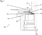
- Fig. 1 shows schematically a section of a vacuum pump 100, which is designed as a turbomolecular pump.
- the turbomolecular pump 100 comprises a rotor 110 with a rotor shaft 112 and several rotor disks, of which a rotor disk 114 is in the area of a labyrinth seal 116 in Fig. 1 shown.
- turbomolecular pump 110 comprises a stator 120, of which Fig. 1 however, only one labyrinth hub 122 is shown.
- the rotor 110 rotates very quickly relative to the stator 120, for example at a speed of several 10,000 revolutions per minute.
- the rotor hub 112 and the rotor disk 114 are therefore among the rotating components of the vacuum pump or turbomolecular pump 100, while the stator 120 with the labyrinth hub 122 are among the non-rotating components of the turbomolecular pump 100.
- turbomolecular pump 100 During operation of the turbomolecular pump 100, for example, it is necessary to record or measure physical or chemical properties of components of the turbomolecular pump 100 in order to ensure long-term operational stability. These properties include, for example, the temperature of the rotor 110.
- the turbomolecular pump 110 comprises an RFID transponder 130, which is attached to the rotor disk 114 by means of a screw connection 132.
- the RFID transponder 130 is also referred to as an RFID tag.
- a temperature sensor 134 is integrated into the RFID transponder 130.
- the counterpart to the RFID transponder is an RFID reader 140, which is attached to the labyrinth hub 122 of the stator 120, for example by means of a screw connection or by gluing.
- the RFID transponder 130 and the RFID reader 140 together form an RFID system, i.e. a system for identification that operates in the radio frequency range (RFID).
- RFID transponder 130 has a microchip on which a unique identifier is stored.
- the RFID transponder 130 is a passive device that does not include an energy storage device such as a battery. This means that the temperature sensor 134 also does not have its own energy source. Instead, the RFID transponder 130 and the temperature sensor 134 are supplied with energy by means of the RFID reader 140, i.e. by means of electromagnetic waves that the RFID reader 140 emits.
- the RFID reader 140 sends a query signal in the direction of the RFID transponder 130 by means of an antenna, which is described in more detail below.
- the query signal is received by an antenna of the RFID transponder 130 and serves on the one hand to activate or "wake up" the RFID transponder 130.
- the query signal and/or other signals of the RFID reader 140 are converted by means of a rectifier of the RFID transponder 130 into signals for supplying energy to both the RFID transponder 130 and the integrated temperature sensor 134.
- the query signal of the RFID reader 140 is read by the electronics of the RFID transponder 130 in order to send a signal with the unique identifier of the RFID transponder 130 back to the RFID reader 140 in response to this signal. This ensures that correct communication between the RFID transponder 130 and the RFID reader 140 and no signals from other devices or interference signals are received.
- the microchip of the RFID transponder 130 is used to record measured values or data from the integrated temperature sensor 134.
- the RFID transponder 130 includes a microcontroller and a voltage regulator, which are mounted on a common circuit board 300 (see FIG. Fig. 3 ) or are integrated into it together with an antenna 310.
- the recorded measured values or data of the temperature sensor 134 are transmitted to the RFID reader 140 via an amplitude modulation of the electromagnetic field emitted by the RFID transponder 130.
- the amplitude modulation is carried out, for example, by switching a load resistor on and off, which is also referred to as load modulation.
- load modulation At frequencies that are used for RFID communication and are, for example, 13.56 MHz, switching the additional load resistor creates signals of additional frequencies, i.e. so-called subcarrier frequencies. These subcarrier frequencies are used for data transmission between the RFID transponder 130 and the RFID reader 140.
- the RFID reader 140 includes a bandpass filter for the subcarrier frequencies. By demodulating the signals received by the RFID reader 140, signals or data are generated that can be identified and interpreted as measurement data from the temperature sensor 134 using electronics in the RFID reader 140. In the present embodiment, evaluation electronics for the measurement data from the temperature sensor 134 are therefore integrated into the RFID reader 140.
- the RFID reader 140 comprises an antenna for sending and receiving the signals described above, a high-frequency reader chip, a microcontroller and an adaptation circuit which comprises, for example, coils and digitally tunable capacitors.
- the electronics of the RFID reader 140 serve, on the one hand, to regulate the transmission power of the antenna of the RFID reader 140 and to decode the modulated electromagnetic field in order to interpret the signals transmitted by the RFID transponder 130 as data from the temperature sensor 134.
- the electronics of the RFID reader 140 are also connected to a drive electronics (not shown) of the vacuum pump 100, so that the drive electronics of the vacuum pump 100 can be used to access the RFID reader 140 or the data provided by it.
- drive electronics not shown
- known software protocols are used, for example.
- the RFID transponder 130 is arranged within the range of the RFID reader 140 in order to ensure wireless energy transmission and data communication between the RFID transponder 130 and the RFID reader 140.
- the distance between the respective antennas of the RFID transponder 130 and the RFID reader 140 is typically in the range of a few millimeters.
- a pump-specific adaptation of an electrical oscillating circuit of the RFID transponder 130 to a resonance frequency of the RFID communication is required.
- such an electrical oscillating circuit of the RFID transponder 130 is calibrated taking into account the given distance between the RFID transponder 130 and the RFID reader 140 or between their antennas.
- the antennas of the RFID transponder 130 and the RFID reader 140 should also have a sufficient axial distance, ie along the rotor axis 112, ie in Fig. 1 in the vertical direction, relative to surfaces of other metallic parts or components of the vacuum pump 110, in order to prevent electromagnetic losses in the material of these components.
- a sufficient axial distance is, for example, 2 to 3 mm. If such a distance between the antennas of the RFID transponder 130 and the RFID reader 140 relative to metallic components of the vacuum pump 100 is to be undercut, suitable shielding, for example by means of a ferrite layer (not shown), is necessary.
- the temperature sensor 134 is integrated into the RFID transponder 130, no further components are required to measure the temperature of the rotor 110, ie in addition to the RFID transponder 130 and the RFID reader 140. Since high centrifugal forces occur during operation of the turbomolecular pump 100 due to the high speeds of the rotor 110, the transponder 130 is arranged as close as possible to a rotational axis of the rotor shaft 112 (see also Fig. 2 ), ie radially in the region of the inner diameter of the rotor disk 114, ie as close as possible to this inner diameter.
- the RFID transponder 130 including its antenna 310 and the temperature sensor 134 is designed as an embedded printed circuit board 300 or embedded PCB board (see also Fig. 2 and 3 ).
- the components of the RFID transponder 130, including the antenna and the temperature sensor 134, are integrated into the material of the circuit board 300 in order to protect these components, including the antenna 310 and the temperature sensor 134, from the high centrifugal forces.
- the components of the RFID transponder 130 are applied to a PCB board using standardized manufacturing processes, for example, and reinforced with a suitable potting compound based on a two-component epoxy in order to achieve additional protection against the centrifugal forces that occur through such reinforcement using potting compound.
- a circuit board substrate and/or antenna substrate is advantageously used which has a suitably high yield strength with corresponding temperature stability at a specified temperature and a specified speed of the rotor 110 of the turbomolecular pump 100.
- the temperature sensor 134 is designed as a digital temperature sensor, wherein the thermal coupling between the temperature sensor 134 and the rotor shaft 112 can be optimized, for example, by means of a "thermal pad" (i.e. by means of a solder contact for thermal coupling).
- a copper line in the circuit board 300 of the RFID transponder 130 is guided to a position that has direct contact, for example by means of a metallic contact surface, or indirect contact, for example by means of a contact surface of a screw head when screwing the circuit board of the RFID transponder, with the material of the rotor shaft 112.
- the temperature sensor 134 can also be implemented by a temperature-sensitive design of the antenna 310 of the RFID transponder 130.
- other electronic components of the RFID transponder 130 can also have temperature-dependent properties that can be detected in order to determine the temperature of the RFID transponder 130 and thus of the rotor 110 based on these detected properties.
- the temperature sensor 134 can also be arranged outside the RFID transponder 130.
- the Temperature sensor 134 can, for example, be arranged at a position where the temperature at the rotor 110 of the turbomolecular pump 100 is expected to be more than 85°C during operation. In such a case, the electronics of the RFID transponder 130 should be arranged at a position on the rotor 110 where the temperature is always less than 85°C.
- the electronics of the RFID reader 140 are connected via signal lines (not shown) via vacuum feedthroughs of the turbomolecular pump 100 to its drive electronics or control electronics (not shown).
- the evaluation electronics for the measurement data of the temperature sensor 134 are integrated into the RFID reader 140 in the present embodiment.
- the evaluation electronics for the data that the RFID reader 140 receives from the RFID transponder 130 can also be integrated into the drive electronics of the turbomolecular pump 100 or into a separate module outside the turbomolecular pump 100.
- the entire electronics of the RFID reader 140 i.e. not just the evaluation electronics, can be integrated in a controller of the turbomolecular pump 100 and thus be arranged away from the antenna of the RFID reader 140.
- the antenna of the RFID reader 140 is connected to the electronics integrated in the controller of the turbomolecular pump 100 via a coaxial cable.
- the length of such a coaxial cable should, however, be as short as possible, and separating the shielding of such a coaxial cable to create a vacuum feedthrough can lead to energy losses.
- the electronics of the RFID reader 140 are arranged on a common board with the antenna of the RFID reader 140 in the interior of the turbomolecular pump 100, ie within its vacuum area.
- a coaxial cable is therefore not required in this embodiment. required.
- the electronics of the RFID reader 140 are controlled via a digital interface, for example 12C or SPI, and the required signal lines are connected to the controller of the turbomolecular pump 100 via a vacuum feedthrough.
- the components For communication between the RFID transponder 130 and the RFID reader 140, their components, for example their oscillating circuits, are adapted to the frequency for communication between the RFID transponder 130 and the RFID reader 140.
- the frequencies for such RFID communication are, for example, between 10 and 15 MHz.
- a frequency range between 800 and 900 MHz or between 2 and 5 GHz (as a UHF system) can be used, for example for using the RFID transponder 130 at high temperatures.
- the RFID reader 140 supplies the RFID transponder 130 with the integrated temperature sensor 134 with energy at predefined time intervals, for example at a short predefined time interval for every second.
- predefined time intervals for example at a short predefined time interval for every second.
- one or more respective measured values of the temperature sensor 134 i.e. measured values of the temperature of the rotor 110, are transmitted from the RFID transponder 130 to the RFID reader 140 by means of the load modulation described above and evaluated by means of the integrated electronics of the RFID reader 140.
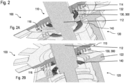
- Fig. 2 shows two perspective views of the section of the vacuum pump or turbomolecular pump 100 according to the invention, which is shown as a sectional view in Fig. 1 and includes the area of the labyrinth seal 116.
- Fig. 2A shows a bottom view of the rotor disk 114 and the labyrinth hub 122
- Fig. 2B a top view of the rotor disk 114 and the labyrinth hub 122.
- the circuit board 300 of the RFID transponder 130 (see also Fig. 3 ) and the circuit board of the RFID reader 140 are designed in a ring shape such that the respective circuit board encloses the rotor shaft 112.
- the two circuit boards of the RFID transponder 130 and the RFID reader 140 enclose the rotor shaft 112 within the labyrinth seal 116 such that the distance of the respective circuit board relative to the axis of rotation of the rotor shaft 112 is minimized.
- the centrifugal forces exerted on the components or elements of the RFID transponder 130 during operation of the turbomolecular pump 100 are also minimized when the RFID transponder 130 rotates together with the rotor 110 of the turbomolecular pump 100.
- the elements or components on the circuit board 300 of the RFID transponder 130, together with the screw connection 132, can cause an additional imbalance of the rotor 110.
- the elements or components of the RFID transponder 130, including the screw connection 132 are distributed over the circumference of the circuit board of the RFID transponder 130 in such a way that a sum vector of individual imbalances of the components and the antenna of the RFID transponder 130, including the screw connection 132, is minimized in terms of magnitude and is ideally the zero vector.
- the components or parts of the RFID transponder 130 are to be arranged or distributed over the circumference of the circuit board 300 of the RFID transponder 130 in such a way that the individual imbalances of these components or parts compensate each other.
- Fig. 3 shows a top view of a respective embodiment of the circuit board 300 of the RFID transponder 130 (cf. Fig. 1 and 2 ) with a respective embodiment of the antenna 310.
- Fig. 3A shows a first embodiment of the antenna 310, in which individual turns of a conductor track 320 run concentrically and circularly on the circuit board 300. Starting with an outer turn, the diameter of the conductor track 320 decreases with each revolution over the circular Board 300 to the innermost winding.
- Fig. 3B shows a second embodiment of the antenna 310 with a half-shell-shaped arrangement of conductor tracks 320.
- a larger shape of the antenna 310 can be achieved compared to the half-shell arrangement of the conductor track 320 of Fig. 3B
- the maximum of the electromagnetic field emitted by the antenna 310 is in the first embodiment of Fig. 3A
- the centre of the antenna i.e. in the area of the axis of rotation of the rotor shaft 112 (cf. Fig. 1 and 2 ).
- the electromagnetic field is created coaxially around the rotor shaft 112. This makes the second embodiment of Fig. 3B less susceptible to interference with the RFID communication between the RFID transponder 130 and the RFID reader 140.
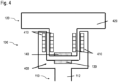
- Fig. 4 shows an alternative embodiment for the arrangement of the RFID transponder 130 on the rotor 110 of the turbomolecular pump 100 and the RFID reader 140 on the stator 120 of the turbomolecular pump 100, specifically in the region of a magnetic bearing 400.
- the magnetic bearing 400 is designed as a permanent bearing and comprises two stacks of permanent magnets 410, one of which is arranged on the rotor shaft 112 and another on a pin of a high vacuum star 420 of the stator 120.
- the RFID transponder 130 is in turn designed as a circuit board in which the components of the RFID transponder 130 are embedded. Furthermore, the RFID transponder 130 or its circuit board is arranged concentrically to the axis of rotation of the rotor shaft 112, so that the axis of rotation of the rotor shaft 112 represents a central axis or axis of symmetry for the RFID transponder 130. This also applies to the RFID reader 140, the components of which are consequently also embedded in a circuit board and which is also symmetrical to the axis of rotation of the Rotor shaft 112 is arranged. The axis of rotation of the rotor shaft 112 thus forms a common central axis or axis of symmetry for both the RFID transponder and the RFID reader 140.
- the above statements regarding the features of the circuit boards of the RFID transponder 130 and the RFID reader 140 also apply mutatis mutandis to the embodiment of Fig. 4 .
- the features include, among others, the possibly required shielding of the RFID transponder 130, its armouring with the aid of a potting compound, the cabling including a vacuum feedthrough for the RFID reader 140, the two embodiments of the antennas, which are shown in Fig. 3 and the cyclical energy and data transmission between the RFID transponder 130 and the RFID reader 140.
- Fig. 5 shows a further embodiment of the vacuum pump or turbomolecular pump 100 according to the invention, in which an RFID communication between the RFID transponder 130 and the RFID reader 140 is provided in a different area of the rotor shaft 112 than in the embodiments of Fig. 1 to 4 .
- the RFID transponder and the RFID reader are arranged in an area of a drive motor of the vacuum pump, ie in the axial direction along the rotor shaft 112 in an axial area of a Holweck pump stage 500 of the vacuum pump 100 and beyond or below a projection 510 of the rotor shaft 112.
- the RFID transponder and the RFID reader are arranged either in an area of drive magnets 520 of the rotor shaft 112 or in an area of a balancing ring 530 of the rotor shaft 112.
- the RFID transponder 130 and the RFID reader 140 are in Fig. 5 not explicitly shown. However, their arrangement is basically the same as in Fig. 4 shown arrangement, except that the RFID transponder 130 and the RFID reader 140 are not attached to radially extending surfaces as in Fig. 4 , but are arranged on axially extending surfaces of the rotor shaft 112 or a corresponding element of a stator (not shown) of the drive motor. Otherwise, the above statements regarding the RFID transponder 130 and the RFID reader 140 also apply analogously to the embodiment of Fig. 5 .
- the RFID transponder 130 can comprise further sensors or be communicatively connected to such sensors on the rotor shaft 112. Examples of such sensors are gyroscopes or strain gauges.
- the combination of RFID transponder 130 and RFID reader 140 can be used to determine a coating thickness, for example on the rotor shaft 112, if deposits on components of the turbomolecular pump 100 are to be expected due to the vacuum process or the use of the turbomolecular pump 100. This can be caused, for example, by reactive gases that are conveyed by means of the turbomolecular pump 100. From a predetermined coating thickness or limit thickness, such deposits impair the operation of the turbomolecular pump 100.
- the power radiated by the RFID reader 140 which is necessary for RFID communication, represents a measure of the coating of the antennas of the RFID transponder 130 and the RFID reader 140 with metals or semiconductor materials.
- the coating thickness due to deposits in the turbomolecular pump 100, ie, for example, on the rotor shaft 112, can be estimated by recording the power radiated by the RFID reader 140 as a function of time, ie at regular time intervals.
- the power of the RFID reader 140 required to establish the RFID communication provides information about the existing layer thickness of deposits on the antennas of the RFID transponder 130 and the RFID reader 140 and thus on the rotor shaft 112.
- the change in the layer thickness of the deposits can be recorded and monitored based on the change in the power required for RFID communication at predetermined time intervals.
Landscapes
- Engineering & Computer Science (AREA)
- Mechanical Engineering (AREA)
- General Engineering & Computer Science (AREA)
- Compressors, Vaccum Pumps And Other Relevant Systems (AREA)
- Non-Positive Displacement Air Blowers (AREA)
Priority Applications (1)
| Application Number | Priority Date | Filing Date | Title |
|---|---|---|---|
| EP24220715.7A EP4506572A3 (fr) | 2024-12-17 | 2024-12-17 | Pompe à vide |
Applications Claiming Priority (1)
| Application Number | Priority Date | Filing Date | Title |
|---|---|---|---|
| EP24220715.7A EP4506572A3 (fr) | 2024-12-17 | 2024-12-17 | Pompe à vide |
Publications (2)
| Publication Number | Publication Date |
|---|---|
| EP4506572A2 true EP4506572A2 (fr) | 2025-02-12 |
| EP4506572A3 EP4506572A3 (fr) | 2025-07-09 |
Family
ID=93926234
Family Applications (1)
| Application Number | Title | Priority Date | Filing Date |
|---|---|---|---|
| EP24220715.7A Pending EP4506572A3 (fr) | 2024-12-17 | 2024-12-17 | Pompe à vide |
Country Status (1)
| Country | Link |
|---|---|
| EP (1) | EP4506572A3 (fr) |
Family Cites Families (3)
| Publication number | Priority date | Publication date | Assignee | Title |
|---|---|---|---|---|
| DE102005041500A1 (de) * | 2005-09-01 | 2007-03-08 | Leybold Vacuum Gmbh | Vakuumpumpe |
| DE102008019472A1 (de) * | 2008-04-17 | 2009-10-22 | Oerlikon Leybold Vacuum Gmbh | Vakuumpumpe |
| DE102020204904A1 (de) * | 2020-04-17 | 2021-10-21 | Fraunhofer-Gesellschaft zur Förderung der angewandten Forschung eingetragener Verein | Vakuumvorrichtung |
-
2024
- 2024-12-17 EP EP24220715.7A patent/EP4506572A3/fr active Pending
Also Published As
| Publication number | Publication date |
|---|---|
| EP4506572A3 (fr) | 2025-07-09 |
Similar Documents
| Publication | Publication Date | Title |
|---|---|---|
| DE3922556C3 (de) | Anordnung zur kontaktlosen Energie- und Sensorsignalübertragung | |
| EP1434698B1 (fr) | Systeme pour transmettre des grandeurs concernant l'etat de pneumatiques | |
| EP2449276B1 (fr) | Palier à unité de production d'énergie | |
| EP3044735B1 (fr) | Caractérisation rfid de pièces métalliques amovibles pour machines-outils | |
| EP1666836B1 (fr) | Capteur de couple et capteur de rotation | |
| EP3510361B1 (fr) | Capteur de position angulaire et élément statorique pour celui-ci | |
| EP2415143A1 (fr) | Moteur électrique | |
| EP3482876A1 (fr) | Disque abrasif, machine-outil portative et procédé de commande | |
| EP1102207B1 (fr) | Dispositif d'étiquette | |
| EP2863184B1 (fr) | Capteur de rotation avec alimentation autonome en énergie | |
| EP3804101B1 (fr) | Moteur électrique | |
| DE10011820B4 (de) | Messeinrichtung für Wälzlager | |
| EP2116324A1 (fr) | Dispositif de transmission sans fil de signaux entre deux parties d'une machine de traitement | |
| DE102016226293A1 (de) | Bürstenlose elektrische Maschine | |
| EP4506572A2 (fr) | Pompe à vide | |
| DE10024035B4 (de) | Komponente | |
| DE102016106112A1 (de) | Gleitlager mit Verschleissüberwachung und zugehöriges Verfahren | |
| EP1920160A1 (fr) | Pompe a vide | |
| EP2113758A2 (fr) | Capteur de couple à système de télémétrie | |
| EP0935541A1 (fr) | Dispositif pour determiner la position angulaire du volant de direction dans une automobile | |
| EP4010124B1 (fr) | Centrifugeuse | |
| EP2250612A1 (fr) | Dispositif équipé d un transpondeur rfid dans un objet électroconducteur et procédé de fabrication correspondant | |
| US20230166340A1 (en) | Rfid arrangements for rotatable work tools | |
| DE102014210547B4 (de) | Verfahren und Anordnung zur Ermittlung einer Drehzahl und/oder einer Winkelposition eines Lagers | |
| DE102022115502B3 (de) | Vorrichtung zur Erfassung von Messwerten in einer Maschine und kontaktlosen Signalübertragung, sowie Maschinenbaugruppe mit dieser Vorrichtung |
Legal Events
| Date | Code | Title | Description |
|---|---|---|---|
| PUAI | Public reference made under article 153(3) epc to a published international application that has entered the european phase |
Free format text: ORIGINAL CODE: 0009012 |
|
| STAA | Information on the status of an ep patent application or granted ep patent |
Free format text: STATUS: THE APPLICATION HAS BEEN PUBLISHED |
|
| AK | Designated contracting states |
Kind code of ref document: A2 Designated state(s): AL AT BE BG CH CY CZ DE DK EE ES FI FR GB GR HR HU IE IS IT LI LT LU LV MC ME MK MT NL NO PL PT RO RS SE SI SK SM TR |
|
| PUAL | Search report despatched |
Free format text: ORIGINAL CODE: 0009013 |
|
| AK | Designated contracting states |
Kind code of ref document: A3 Designated state(s): AL AT BE BG CH CY CZ DE DK EE ES FI FR GB GR HR HU IE IS IT LI LT LU LV MC ME MK MT NL NO PL PT RO RS SE SI SK SM TR |
|
| RIC1 | Information provided on ipc code assigned before grant |
Ipc: F04D 27/00 20060101ALI20250530BHEP Ipc: F04D 19/04 20060101AFI20250530BHEP |
|
| STAA | Information on the status of an ep patent application or granted ep patent |
Free format text: STATUS: REQUEST FOR EXAMINATION WAS MADE |
|
| 17P | Request for examination filed |
Effective date: 20251114 |