EP4506708A1 - Dispositif de résonance magnétique doté d'une unité de commutation et procédé de fonctionnement d'un tel dispositif de résonance magnétique - Google Patents
Dispositif de résonance magnétique doté d'une unité de commutation et procédé de fonctionnement d'un tel dispositif de résonance magnétique Download PDFInfo
- Publication number
- EP4506708A1 EP4506708A1 EP23190884.9A EP23190884A EP4506708A1 EP 4506708 A1 EP4506708 A1 EP 4506708A1 EP 23190884 A EP23190884 A EP 23190884A EP 4506708 A1 EP4506708 A1 EP 4506708A1
- Authority
- EP
- European Patent Office
- Prior art keywords
- magnetic resonance
- plug connection
- unit
- resonance device
- resonance apparatus
- Prior art date
- Legal status (The legal status is an assumption and is not a legal conclusion. Google has not performed a legal analysis and makes no representation as to the accuracy of the status listed.)
- Pending
Links
Images


Classifications
-
- G—PHYSICS
- G01—MEASURING; TESTING
- G01R—MEASURING ELECTRIC VARIABLES; MEASURING MAGNETIC VARIABLES
- G01R33/00—Arrangements or instruments for measuring magnetic variables
- G01R33/20—Arrangements or instruments for measuring magnetic variables involving magnetic resonance
- G01R33/28—Details of apparatus provided for in groups G01R33/44 - G01R33/64
- G01R33/32—Excitation or detection systems, e.g. using radio frequency signals
- G01R33/36—Electrical details, e.g. matching or coupling of the coil to the receiver
- G01R33/3614—RF power amplifiers
-
- A—HUMAN NECESSITIES
- A61—MEDICAL OR VETERINARY SCIENCE; HYGIENE
- A61B—DIAGNOSIS; SURGERY; IDENTIFICATION
- A61B5/00—Measuring for diagnostic purposes; Identification of persons
- A61B5/05—Detecting, measuring or recording for diagnosis by means of electric currents or magnetic fields; Measuring using microwaves or radio waves
- A61B5/055—Detecting, measuring or recording for diagnosis by means of electric currents or magnetic fields; Measuring using microwaves or radio waves involving electronic [EMR] or nuclear [NMR] magnetic resonance, e.g. magnetic resonance imaging
-
- G—PHYSICS
- G01—MEASURING; TESTING
- G01R—MEASURING ELECTRIC VARIABLES; MEASURING MAGNETIC VARIABLES
- G01R33/00—Arrangements or instruments for measuring magnetic variables
- G01R33/20—Arrangements or instruments for measuring magnetic variables involving magnetic resonance
- G01R33/28—Details of apparatus provided for in groups G01R33/44 - G01R33/64
- G01R33/32—Excitation or detection systems, e.g. using radio frequency signals
- G01R33/36—Electrical details, e.g. matching or coupling of the coil to the receiver
- G01R33/3664—Switching for purposes other than coil coupling or decoupling, e.g. switching between a phased array mode and a quadrature mode, switching between surface coil modes of different geometrical shapes, switching from a whole body reception coil to a local reception coil or switching for automatic coil selection in moving table MR or for changing the field-of-view
-
- G—PHYSICS
- G01—MEASURING; TESTING
- G01R—MEASURING ELECTRIC VARIABLES; MEASURING MAGNETIC VARIABLES
- G01R33/00—Arrangements or instruments for measuring magnetic variables
- G01R33/20—Arrangements or instruments for measuring magnetic variables involving magnetic resonance
- G01R33/44—Arrangements or instruments for measuring magnetic variables involving magnetic resonance using nuclear magnetic resonance [NMR]
Definitions
- the invention relates to a magnetic resonance device with a switching unit and a method for operating such a device.
- MR magnetic resonance
- MRI magnetic resonance tomography
- a human or animal patient is positioned in a main magnetic field of a magnetic resonance device.
- high-frequency (HF) pulses are usually emitted into the patient using a high-frequency antenna unit of a magnetic resonance device.
- the generated RF pulses excite nuclear spins in the patient, triggering spatially encoded magnetic resonance signals.
- the magnetic resonance signals are received by the magnetic resonance device and used to reconstruct magnetic resonance images.
- Local coils are usually used to excite signals in magnetic resonance devices with an ultra-high main magnetic field (UHF), e.g. 7 Tesla or more.
- UHF main magnetic field
- body coil whole-body transmit coil
- the magnetic resonance device on the patient table often has one or more local coil connection units, for example in the form of a or several sockets. Depending on which region is to be measured, a corresponding local coil is connected to one of the several local coil connection units.
- Each of the several local coil connection units has a number of transmit or receive channels.
- the cable length of a plug-in local coil is usually chosen to be as short as possible. Therefore, the local coil suitable for a specific measurement is connected to a nearby local coil connection unit.
- the total number of transmit or receive channels of the magnetic resonance device is limited, so that the number of local coil connection units is also limited and their spatial distribution across the patient table is restricted.
- the object of the present invention can be seen as improving the workflow during a measurement using local coils.
- the object can be seen as providing a plurality of local coil connection units for connecting local coils, in particular transmit-receive coils, in a cost-effective manner.
- a magnetic resonance device which comprises a power amplification unit which is designed to provide transmission signals to be transmitted by means of the magnetic resonance device, and comprises a switching unit.
- the transmission signals to be transmitted are suitable for example for implementing a parallel transmission technique (pTx).
- the switching unit comprises an actuator unit, a first plug connection part which is connected to the power amplification unit, and a plurality of second plug connection parts.
- the Actuator unit designed to move, in particular to position, the first plug connection part relative to the plurality of second plug connection parts in such a way that an electrical connection, in particular a plug connection, is established between the first plug connection part and a predetermined plug connection part of the plurality of second plug connection parts.
- the actuator unit is designed to reposition the first plug connection part between the plurality of second plug connection parts.
- the magnetic resonance device comprises a plurality of local coil connection units, in particular plug-in locations, each of which is designed to connect a local coil to the magnetic resonance device, wherein each of the plurality of second plug-in connection parts is electrically connected to one of the plurality of local coil connection units.
- the invention advantageously simplifies the distribution of an RF transmission power to a plurality of local coil connection units with little effort for additional RF lines and/or switching contacts.
- the magnetic resonance device in particular the power amplification unit, has N (N ⁇ 1) transmission channels that are connected to the first plug connection part; the switching unit has, for example, M (M > 1) second plug connection parts and M local coil connection units connected thereto.
- M (M > 1) second plug connection parts M local coil connection units connected thereto.
- each of the M local coil connection units can then be connected to the N transmission channels via the switching unit.
- NxM transmission channels would usually be required for this instead of just N transmission channels, i.e. the number of transmission channels of the power amplification unit (and the associated hardware such as amplifiers, etc.) can advantageously be reduced.
- plug-in connection parts or a plug-in connection By using plug-in connection parts or a plug-in connection, a connection can be provided that enables a high level of immunity to interference, a high switching capacity (usually required power range approx. 8-32 kW peak) and/or only low losses. Such plug-in connections are therefore significantly superior to any semiconductor switches. Furthermore, any reflections at open ends can advantageously be avoided. Such a proposed plug-in connection is advantageously suitable for magnetic fields or MR compatible. In addition, the proposed switching unit can be implemented relatively inexpensively.
- the predetermined second plug connection part can be predetermined, for example, by the operator of the magnetic resonance device manually selecting a local coil connection unit connected to the second plug connection part. It is also conceivable that such a selection is made automatically depending on a magnetic resonance examination to be carried out. If, for example, a head examination is to be carried out, a connection can be automatically established with the second plug connection part, which is connected to the local coil connection unit that is suitable or best suited for connecting a head coil.
- the first plug connection part corresponds mechanically and/or electrically to each of the plurality of second plug connection parts.
- the first plug connection part forms a counterpart to each of the plurality of second plug connection parts.
- the first plug connection part is a plug and each of the plurality of second plug connection parts is a corresponding socket.
- the first connector part is a plug and the plurality of second connector parts are sockets corresponding to the plug.
- the first A first plug connection part has a socket and the second plurality of plug connection parts have plugs corresponding to the socket.
- the first plug connection part and the second plug connection part connected thereto form a system for transmitting information and/or electrical energy.
- the transmission signals to be transmitted can advantageously be transmitted via an electrical connection.
- each of the plurality of second plug connection parts is designed to establish an electrical connection with the first plug connection part, so that the transmission signals can be transmitted via this electrical connection.
- the first plug connection part has a first, in particular geometric, shape
- each of the plurality of second plug connection parts has a second, in particular geometric, shape, wherein the first shape and the second shape are coordinated with one another such that they are mechanically guided and/or engage with one another when the electrical connection is established.
- the first plug connection part and/or the plurality of second plug connection parts have a housing.
- the shape of the plug connection part can be determined in particular by the shape of the housing of the plug connection part.
- the first plug connection part and/or the plurality of second plug connection parts have electrical contact elements corresponding to one another, for example electrical contact pins and/or contact openings.
- the contact elements are designed to form a power-resistant contact (in the connected state).
- a single contact is designed to transmit a peak power of more than 0.5 kW, in particular more than 1 kW, in particular more than 1.5 kW.
- a single contact is designed to transmit an average power of more than 50 W, in particular more than 100 W, in particular more than 150 W.
- the switching unit contact is designed to transmit a total peak power of more than 8 kW, in particular more than 12 kW, in particular more than 16 kW.
- an individual contact is designed to transmit an average power of more than 0.8 kW, in particular more than 1.2 kW, in particular more than 1.6 kW.
- the first plug connection part and/or the plurality of second plug connection parts have at least one electrical contact pin and/or at least one contact opening corresponding thereto.
- the shape of the plug connection parts can be determined in particular by electrical contact pins of the plug connection part and/or their receptacles on the corresponding plug connection part.
- the electrical contact pins usually point outwards (male part of a plug connection).
- the receptacles are usually contact openings pointing inwards (female part of a plug connection).
- a plug connection part can have both contact pins and contact openings at the same time, i.e. plug elements of both sexes.
- the first connector part and/or the plurality of second connector parts comprise at least one coaxial electrical contact element.
- the first plug connection part and/or the plurality of second plug connection parts comprise at least one coaxial contact pin.
- a coaxial connection advantageously enables particularly low-noise signal transmission.
- the first connector part and/or the plurality of second connector parts comprise at least one mechanical guide element.
- the first plug connection part and/or the plurality of second plug connection parts have at least one mechanical guide pin and/or at least one guide opening corresponding thereto.
- the at least one mechanical guide pin is advantageously of solid design.
- the first connector part comprises a mechanical guide pin and the plurality of second connector parts each comprise a guide opening corresponding to the mechanical guide pin.
- the at least one mechanical guide pin together with the at least one corresponding guide opening enables a precise and/or reliable plugging process of the first plug connection part with the respective second plug connection part.
- the actuator unit preferably comprises at least one actuator.
- the actuator is in particular a component that converts a control signal, in particular an electrical one, into mechanical movement.
- the control signal can be transmitted, for example, from a system control unit of the magnetic resonance device to the actuator unit.
- the actuator unit preferably comprises an actuator control unit that is designed to receive control signals from the system control unit.
- the system control unit is preferably designed to send the control signals to the actuator control unit depending on a magnetic resonance sequence to be carried out, in particular one or more local coils selected for this purpose. If, for example, a measurement of the patient's head is carried out according to the magnetic resonance sequence, the actuator unit is advantageously used to establish a connection between the first plug connection part and the second plug connection part, which is connected to the local coil connection unit, to which a head coil is suitable for connecting.
- the actuator unit in particular the at least one actuator, comprises at least one pneumatic drive. Forces for moving the first plug connection part are preferably transmitted by means of a gas, for example compressed air.
- the actuator unit in particular the at least one actuator, comprises at least one hydraulic drive. Forces for moving the first plug connection part are preferably transmitted by means of a liquid, for example an oil (compatible with any standards).
- the at least one pneumatic drive and/or the at least one hydraulic drive are preferably designed to convert pressure energy into kinetic energy in order to move the first plug connection part.
- the actuator unit in particular the at least one actuator, comprises at least one electric motor.
- the at least one electric motor is preferably an electromechanical converter that converts electrical power into mechanical power in order to move the first plug connection part.
- the at least one electric motor is shielded.
- the shielding advantageously reduces interference.
- the magnetic resonance device preferably comprises a magnet for generating a main magnetic field, wherein the at least one electric motor comprises a rotor which interacts with the main magnetic field of the magnetic resonance device as a permanent magnetic field of the electric motor.
- the main magnetic field which is already present can therefore be used to operate the electric motor.
- the actuators proposed above are suitable for carrying out a switching process even in a strong magnetic field.
- the actuator unit preferably comprises a roller extension.
- the first plug connection part can in particular be arranged on a guide rail.
- a transmission line is used which has a diameter of approx. 5 mm and a bending circle diameter of approx. 8 cm.
- a winding mandrel with a diameter of approx. 10 cm and spring return force is conceivable. In this case, two windings in particular would be sufficient to provide approx. 50 cm of travel for the plug connection part.
- the actuator unit is designed to move the first plug connection part in at least two spatial directions (movement directions).
- the plurality of second plug connection parts are arranged along a straight line, wherein this straight line corresponds to a first of the movement directions of the actuator unit.
- the plurality of second plug connection parts are arranged in a plane, wherein the actuator unit is designed to move the first plug connection part parallel to the plane in order to bring the first plug connection part into the vicinity of one of the plurality of second plug connection parts and/or into alignment with one of the plurality of second plug connection parts.
- a second direction of movement of the actuator unit is, for example, a direction perpendicular to the first direction of movement, in order to connect the first plug connection part to one of the several second plug connection parts by movement in this direction and to release the connection again by movement in the opposite direction.
- a plurality of second plug connection parts are arranged in a plane, wherein the actuator unit is designed to displace the first plug connection part perpendicular to the plane in order to connect the first plug connection part to one of the plurality of second plug connection parts and to release the connection again by moving in the opposite direction.
- the switching unit is advantageously arranged in the same room in which the (remaining) magnetic resonance device, in particular its magnet unit, is located.
- the magnetic resonance device preferably comprises a patient table and a magnet unit for generating a main magnetic field of the magnetic resonance device, wherein the switching unit is arranged in the region of the patient table and/or in the vicinity of the magnet unit.
- the switching unit By arranging the switching unit on the magnetic resonance device, short signal lines can advantageously be made possible.
- a possible arrangement of the switching unit in a room adjacent to the room in which the magnetic resonance device is located would, however, require relatively long signal lines. This also allows line losses that would otherwise exist to be minimized, so that the dielectric strength requirements for the electrical connections can be significantly reduced.
- the magnetic resonance device has a main magnet with a strength of at least 5 Tesla.
- local coils in particular RF transmit coils, can be used particularly effectively by means of the local coil connection units.
- the magnetic resonance device comprises at least one local coil which is designed to emit high-frequency pulses according to the provided transmission signals into an examination region of the magnetic resonance device.
- a method for ensuring a correct connection is proposed.
- at least one high-frequency pulse is emitted using a magnetic resonance device as described above and its reflection is evaluated in amplitude and/or phase.
- the evaluated information can be used to determine whether the switching unit has established a connection with the correct second connector part and the associated local coil connection unit.
- the at least one high-frequency pulse is emitted at the beginning of a magnetic resonance sequence. This advantageously allows a possible error to be detected at an early stage.
- the at least one high-frequency pulse has a low amplitude. This advantageously allows the check to be carried out particularly reliably.
- a magnetic resonance device 10 is shown schematically.
- the magnetic resonance device 10 comprises a magnet unit 11, which has a main magnet 12 for generating a strong and in particular temporally constant main magnetic field 13.
- the main magnetic field 13 is in particular an ultra-high magnetic field.
- the magnetic resonance device 10 comprises a patient receiving area 14 for receiving a patient 15.
- the patient receiving area 14 in the present embodiment is cylindrical and is cylindrically surrounded in a circumferential direction by the magnet unit 11.
- the patient 15 can be pushed into the patient receiving area 14 by means of a patient support device 16 of the magnetic resonance device 10.
- the patient support device 16 has a patient table 17 designed to be movable within the patient receiving area 14.
- the magnet unit 11 further comprises a gradient coil unit 18 for generating magnetic field gradients that are used for spatial coding during imaging.
- the gradient coil unit 18 is controlled by means of a gradient control unit 19 of the magnetic resonance device 10.
- the magnet unit 11 further comprises a high-frequency antenna unit 20, which in the present exemplary embodiment is designed as a body coil that is permanently integrated into the magnetic resonance device 10.
- body region-specific local coils are used, such as a head coil 27 or a spinal coil 28 here, which are designed to radiate high-frequency magnetic resonance sequences into an examination room that is essentially formed by a patient receiving area 14 of the magnetic resonance device 10.
- Main magnetic field 13 excites atomic nuclei.
- Magnetic resonance signals are generated by relaxation of the excited atomic nuclei.
- the local coils are designed to both transmit RF signals and receive magnetic resonance signals.
- the magnetic resonance device 10 has a system control unit 22 for controlling the main magnet 12, the gradient control unit 19 and for controlling the radio-frequency antenna control unit 21.
- the system control unit 22 centrally controls the magnetic resonance device 10, such as, for example, carrying out a predetermined imaging gradient echo sequence.
- the system control unit 22 includes an evaluation unit (not shown in detail) for evaluating the magnetic resonance signals that are acquired during the magnetic resonance examination.
- the magnetic resonance device 10 also includes a user interface 23 that is connected to the system control unit 22. Control information such as imaging parameters and reconstructed magnetic resonance images can be displayed on a display unit 24, for example on at least one monitor, of the user interface 23 for medical operators.
- the user interface 23 has an input unit 25 by means of which information and/or parameters can be entered by the medical operating personnel during a measurement process.
- the magnetic resonance device 10 comprises a radio-frequency antenna control unit 21, which has a power amplification unit with a plurality of transmission channels.
- the power amplification unit is designed to provide transmission signals to be transmitted, for example to generate pTx pulses.
- the magnetic resonance device comprises a switching unit 26, which in Fig. 2 and 3 is described in more detail.
- the transmission lines from the power amplifier unit end at a first connector part of the switching unit (cf. Fig. 2 and 3 ).
- a switching unit which comprises an actuator unit, a first plug connection part V 11 which is connected to the power amplification unit of the high-frequency antenna control unit 21, and four second plug connection parts V 21 , V 22 , V 23 , V 24.
- the actuator unit A is designed to position the first plug connection part V 11 relative to the four second plug connection parts such that an electrical connection is established between the first plug connection part V 11 and one of the plurality of second plug connection parts V 21 , V 22 , V 23 , or V 24 , which was in particular previously selected.
- the actuator unit A is able to move the first connector part V 11 in the direction ⁇ x 1 along the connector parts V 21 , V 22 , V 23 , V 24 , which are arranged along a straight line parallel to the direction x 1 .
- the directions x 1 , x 2 , x 3 in Fig. 2 and 3 are preferably orthogonal to each other.
- the respective desired second connector part V 21 , V 22 , V 23 or V 24 can be approached.
- the first connector part V 11 is above the second connector part V 23 after such an approach.
- the actuator unit A is able to move the first connector part V 11 in the direction ⁇ x 3 .
- a connection between the first connector part V 11 and the desired second connector part V 21 , V 22 , V 23 or V 24 can be established or also broken again.
- the connector part V 11 which is above the second connector part V 23 after the approach is moved downwards into the connector part V 23 in order to establish an electrical connection.
- the switching unit 26 further comprises an actuator control unit S, which can receive control signals from the system control unit 22 and convert them into corresponding movements of the first plug connection part V 11 by means of the actuator unit A.
- the system control unit 22 also controls the high-frequency antenna control unit 21 with its power amplification unit, which in the present case comprises eight power amplifiers for each transmission channel.
- the first plug connection part V 11 also has eight electrical contact elements C 1 .
- Such contact elements can be, for example, electrical contact pins which form an electrical connection in corresponding contact elements C 2 , in particular contact openings, when the first plug connection part V 11 is plugged into the desired second plug connection part V 21 , V 22 , V 23 or V 24 .
- the plug-in connection parts V 11 and V 21 , V 22 , V 23 or V 24 can have interlocking guide elements G 1 or G 2 .
- These can be, for example, in particular solid guide pins that penetrate into an opposite opening during the connection process.
- Each of the four second plug connection parts V 11 and V 21 , V 22 , V 23 , V 24 is in turn electrically connected to a corresponding local coil connection unit L 1 , L 2 , L 3 or L 4.
- the eight transmission signals provided by the power amplifier unit can be transmitted via the interconnected plug connection parts to the respective local coil connection unit L 1 , L 2 , L 3 or L 4 .
- the local coil connection units L 1 , L 2 , L 3 , L 4 are arranged on the patient table 17. If, for example, a local coil is to be connected to and operated on the local coil connection unit L 4 , the first plug connection part V 11 is plugged into the second plug connection part V 24 by means of the actuator unit A in order to electrically connect the transmission channels of the power amplifier unit to the local coil connection unit L 4 .
- a switching unit 26 with eight second plug connection parts V 21 , V 22 , V 23 , V 24 , V 25 , V 26 , V 27 , V 28 is shown, which are arranged in two rows that are offset from one another in the direction x 2.
- the eight second plug connection parts V 21 , V 22 , V 23 , V 24 , V 25 , V 26 , V 27 , V 28 are each electrically connected to a local coil connection unit L 1 , L 2 , L 3 , L 4 , L 5 , L 6 , L 7 , L 8 .
- the actuator unit is advantageously designed to move the first plug connection part V 11 also along the direction x 2 in order to be able to establish a connection with one of the second plug connection parts V 21 , V 22 , V 23 , V 24 , V 25 , V 26 , V 27 or V 28 .
- the local coil connection units L 1 , L 2 , L 3 , L 4 , L 5 , L 6 , L 7 , L 8 are distributed here at both ends of the patient table 17.
- this makes it easier to position a local coil in the right place for measurement even if the cable length is short. This also makes it easier to change the coil by replugging the local coils.
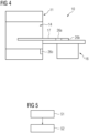
- Fig. 4 Positions are shown which are particularly suitable for arranging the switching unit. For example, this can be arranged at the end of the patient table 17, 26a, or behind the patient table, 26b, or at the front of the magnet unit 11 behind its cover (particularly if the transmission lines go from there into the couch).
- Fig. 5 a method for ensuring a correct connection is shown.
- the power amplification unit provides a transmission signal to be transmitted in order to generate a high-frequency pulse.
- a signal measured by a receiving unit of the magnetic resonance device is evaluated in terms of amplitude and/or phase. If the measured signal is too low, for example, it can be concluded that there is no correct connection between the power amplification unit and the transmitting unit (for example, the local coil if it is a transmit-receive coil). This can be caused in particular by the switching unit not establishing a correct connection.
- the transmission signal to be emitted preferably has a low amplitude.
Landscapes
- Physics & Mathematics (AREA)
- Condensed Matter Physics & Semiconductors (AREA)
- General Physics & Mathematics (AREA)
- Health & Medical Sciences (AREA)
- Life Sciences & Earth Sciences (AREA)
- High Energy & Nuclear Physics (AREA)
- Nuclear Medicine, Radiotherapy & Molecular Imaging (AREA)
- Engineering & Computer Science (AREA)
- Molecular Biology (AREA)
- Pathology (AREA)
- Radiology & Medical Imaging (AREA)
- Biomedical Technology (AREA)
- Heart & Thoracic Surgery (AREA)
- Medical Informatics (AREA)
- Biophysics (AREA)
- Surgery (AREA)
- Animal Behavior & Ethology (AREA)
- General Health & Medical Sciences (AREA)
- Public Health (AREA)
- Veterinary Medicine (AREA)
- Magnetic Resonance Imaging Apparatus (AREA)
Priority Applications (3)
| Application Number | Priority Date | Filing Date | Title |
|---|---|---|---|
| EP23190884.9A EP4506708A1 (fr) | 2023-08-10 | 2023-08-10 | Dispositif de résonance magnétique doté d'une unité de commutation et procédé de fonctionnement d'un tel dispositif de résonance magnétique |
| CN202411081510.6A CN119471514A (zh) | 2023-08-10 | 2024-08-08 | 具有切换单元的磁共振装置和用于运行这种磁共振装置的方法 |
| US18/800,061 US20250052840A1 (en) | 2023-08-10 | 2024-08-10 | Magnetic resonance apparatus with switching unit and method for operating such an apparatus |
Applications Claiming Priority (1)
| Application Number | Priority Date | Filing Date | Title |
|---|---|---|---|
| EP23190884.9A EP4506708A1 (fr) | 2023-08-10 | 2023-08-10 | Dispositif de résonance magnétique doté d'une unité de commutation et procédé de fonctionnement d'un tel dispositif de résonance magnétique |
Publications (1)
| Publication Number | Publication Date |
|---|---|
| EP4506708A1 true EP4506708A1 (fr) | 2025-02-12 |
Family
ID=87567153
Family Applications (1)
| Application Number | Title | Priority Date | Filing Date |
|---|---|---|---|
| EP23190884.9A Pending EP4506708A1 (fr) | 2023-08-10 | 2023-08-10 | Dispositif de résonance magnétique doté d'une unité de commutation et procédé de fonctionnement d'un tel dispositif de résonance magnétique |
Country Status (3)
| Country | Link |
|---|---|
| US (1) | US20250052840A1 (fr) |
| EP (1) | EP4506708A1 (fr) |
| CN (1) | CN119471514A (fr) |
Citations (3)
| Publication number | Priority date | Publication date | Assignee | Title |
|---|---|---|---|---|
| US20130271129A1 (en) * | 2012-04-13 | 2013-10-17 | Helmut Kess | Detecting Unplugged Local Coils in a Nuclear Magnetic Resonance Tomograph |
| US20160139218A1 (en) * | 2013-06-17 | 2016-05-19 | Koninklijke Philips N.V. | Magnetic resonance imaging subject support |
| US20210030306A1 (en) * | 2018-04-09 | 2021-02-04 | Koninklijke Philips N.V. | Automatic positioning of antenna connectors for magnetic resonance imaging |
Family Cites Families (4)
| Publication number | Priority date | Publication date | Assignee | Title |
|---|---|---|---|---|
| DE102006057322A1 (de) * | 2006-12-05 | 2008-06-19 | Siemens Ag | Patientenliege |
| DE102016212043B4 (de) * | 2016-07-01 | 2018-03-01 | Siemens Healthcare Gmbh | Patientenliege mit flexibler HF Sendeleistungsverteilung für einen Magnetresonanztomographen |
| US20210282866A1 (en) * | 2020-03-12 | 2021-09-16 | Clearpoint Neuro, Inc. | Image-guided surgical systems with automated trajectory guide systems and related devices and methods |
| WO2023108023A2 (fr) * | 2021-12-07 | 2023-06-15 | 4D Surgical, Llc | Moteur rotatif ayant un stator de champ magnétique ambiant |
-
2023
- 2023-08-10 EP EP23190884.9A patent/EP4506708A1/fr active Pending
-
2024
- 2024-08-08 CN CN202411081510.6A patent/CN119471514A/zh active Pending
- 2024-08-10 US US18/800,061 patent/US20250052840A1/en active Pending
Patent Citations (3)
| Publication number | Priority date | Publication date | Assignee | Title |
|---|---|---|---|---|
| US20130271129A1 (en) * | 2012-04-13 | 2013-10-17 | Helmut Kess | Detecting Unplugged Local Coils in a Nuclear Magnetic Resonance Tomograph |
| US20160139218A1 (en) * | 2013-06-17 | 2016-05-19 | Koninklijke Philips N.V. | Magnetic resonance imaging subject support |
| US20210030306A1 (en) * | 2018-04-09 | 2021-02-04 | Koninklijke Philips N.V. | Automatic positioning of antenna connectors for magnetic resonance imaging |
Also Published As
| Publication number | Publication date |
|---|---|
| US20250052840A1 (en) | 2025-02-13 |
| CN119471514A (zh) | 2025-02-18 |
Similar Documents
| Publication | Publication Date | Title |
|---|---|---|
| DE102016212724B4 (de) | Größenveränderliche Lokalspulenmatrix mit variabler Entkopplung | |
| EP0583824B1 (fr) | Dispositif de bobines en quadrature pour l'examen mammographique à résonance magnétique | |
| EP3546967B1 (fr) | Matrice de bobine local et procédé de détection d'images | |
| EP3299832B1 (fr) | Bobine locale avec un premier élément de raccordement d'un connecteur, et appareil à résonance magnétique ou lit d'examen avec un deuxième élément de raccordement correspondant | |
| EP1275972A2 (fr) | Assemblage de bobines à haute fréquence pour un appareil à résonance magnétique | |
| DE10126338A1 (de) | Hochfrequenz-Spulenanordnung für ein Kernspintomographie-Gerät und Kernspintomorgraphie-Gerät | |
| DE102016212043B4 (de) | Patientenliege mit flexibler HF Sendeleistungsverteilung für einen Magnetresonanztomographen | |
| DE102016204620B4 (de) | MR-Körperspule | |
| DE102007059522B4 (de) | Magnetresonanzanlage mit verlustleistungsoptimiertem Betrieb | |
| DE102009018608A1 (de) | Mechanische Ausführung eines Interfaces zur Anbindung von MR-Lokalspulen an ein MR-System mit elektrisch und/oder mechanisch anderer Schnittstelle | |
| DE102011089376B4 (de) | Auswahleinheit für ein Magnetresonanzbildgebungssystem | |
| DE102011005433B4 (de) | Verfahren und Hochfrequenz-Kontrolleinrichtung zur Kontrolle einer Hochfrequenzsendeeinrichtung eines Magnetresonanztomographiesystems | |
| EP3555648A1 (fr) | Système à antennes dipôles pour la capture d'images au moyen de méthodes de résonance magnétique nucléaire | |
| DE102010033330B4 (de) | Magnetresonanz-Antennenanordnung, Magnetresonanzgerät und Verfahren zur Akquisition von Magnetresonanzsignalen | |
| DE102006052217B4 (de) | Magnetresonanzanlage mit Empfangsantenneneinrichtung | |
| DE102013214307A1 (de) | Lokale Sendespulen / Sendespulenarray in der Wirbelsäulenbildgebung in einem MRI | |
| EP4118444B1 (fr) | Bobine à double résonance et réseau de bobines à double résonance et leur utilisation | |
| EP3410143B1 (fr) | Connecteur à utiliser dans un appareil à résonance magnétique | |
| DE102008014191A1 (de) | Magnetresonanz-Bildgebungsgerät und Magnetresonanz-Bildgebungsverfahren | |
| EP3187889B1 (fr) | Bobine locale adaptable pour irm | |
| DE102013217012A1 (de) | Lokal-SAR-Reduzierung für z.B. Patienten mit metallischen Implantaten | |
| EP4374184A1 (fr) | Bobine locale et dispositif à résonance magnétique comprenant un mécanisme de sécurité pour empêcher une collision avec un patient | |
| DE10163815A1 (de) | Paralleles MR-Bildgebungsverfahren | |
| DE102023207805A1 (de) | Steckervorrichtung zum Koppeln von Sende-Empfangs-Spulen eines Magnetresonanzsystems mit einer Sende-Empfangs-Steuereinheit des Magnetresonanzsystems, sowie Magnetresonanzsystem | |
| DE102006010003A1 (de) | Zirkulator und Magnet-Resonanz-Gerät |
Legal Events
| Date | Code | Title | Description |
|---|---|---|---|
| PUAI | Public reference made under article 153(3) epc to a published international application that has entered the european phase |
Free format text: ORIGINAL CODE: 0009012 |
|
| STAA | Information on the status of an ep patent application or granted ep patent |
Free format text: STATUS: THE APPLICATION HAS BEEN PUBLISHED |
|
| AK | Designated contracting states |
Kind code of ref document: A1 Designated state(s): AL AT BE BG CH CY CZ DE DK EE ES FI FR GB GR HR HU IE IS IT LI LT LU LV MC ME MK MT NL NO PL PT RO RS SE SI SK SM TR |
|
| STAA | Information on the status of an ep patent application or granted ep patent |
Free format text: STATUS: REQUEST FOR EXAMINATION WAS MADE |
|
| 17P | Request for examination filed |
Effective date: 20250805 |