EP4506743A1 - Traversée de guide d'ondes optiques pour chambre à vide - Google Patents
Traversée de guide d'ondes optiques pour chambre à vide Download PDFInfo
- Publication number
- EP4506743A1 EP4506743A1 EP24192311.9A EP24192311A EP4506743A1 EP 4506743 A1 EP4506743 A1 EP 4506743A1 EP 24192311 A EP24192311 A EP 24192311A EP 4506743 A1 EP4506743 A1 EP 4506743A1
- Authority
- EP
- European Patent Office
- Prior art keywords
- openings
- sealing
- flange
- holding flange
- pressure
- Prior art date
- Legal status (The legal status is an assumption and is not a legal conclusion. Google has not performed a legal analysis and makes no representation as to the accuracy of the status listed.)
- Pending
Links
Images


Classifications
-
- G—PHYSICS
- G02—OPTICS
- G02B—OPTICAL ELEMENTS, SYSTEMS OR APPARATUS
- G02B6/00—Light guides; Structural details of arrangements comprising light guides and other optical elements, e.g. couplings
- G02B6/24—Coupling light guides
- G02B6/42—Coupling light guides with opto-electronic elements
- G02B6/4201—Packages, e.g. shape, construction, internal or external details
- G02B6/4248—Feed-through connections for the hermetical passage of fibres through a package wall
-
- G—PHYSICS
- G02—OPTICS
- G02B—OPTICAL ELEMENTS, SYSTEMS OR APPARATUS
- G02B6/00—Light guides; Structural details of arrangements comprising light guides and other optical elements, e.g. couplings
- G02B6/44—Mechanical structures for providing tensile strength and external protection for fibres, e.g. optical transmission cables
- G02B6/4439—Auxiliary devices
- G02B6/4471—Terminating devices ; Cable clamps
- G02B6/44775—Cable seals e.g. feed-through
Definitions
- the invention relates to an optical waveguide feedthrough for passing a plurality of optical waveguides between an interior of an evacuable vacuum chamber and an environment of the vacuum chamber.
- the invention further relates to an optical waveguide arrangement with such an optical waveguide feedthrough and a method for passing a plurality of optical waveguides between an interior of an evacuable vacuum chamber and an environment of the vacuum chamber using such an optical waveguide feedthrough.
- the object of the invention is therefore to provide an improved solution for feeding a large number of optical waveguides into or out of a vacuum chamber, by means of which the disadvantages of previous approaches can be avoided.
- an optical waveguide feedthrough is provided.
- the optical waveguide feedthrough is configured to pass a plurality of optical waveguides (e.g. single-mode optical fibers and/or multimode optical fibers) between an interior (e.g. chamber interior) of an evacuable vacuum chamber (evacuable space, e.g. ultra-high vacuum chamber) and an (e.g. external) environment of the vacuum chamber.
- optical waveguides e.g. single-mode optical fibers and/or multimode optical fibers
- the optical fiber feedthrough comprises at least one holding flange (e.g. a CF flange) which is designed for fastening to the vacuum chamber, preferably in a pressure-tight manner, and has a plurality of through-openings (e.g. through-holes, in particular flat countersunk holes).
- the through-openings are in turn each designed for receiving, preferably in a pressure-tight manner, one optical fiber of the plurality of optical fibers.
- each of the through-openings (of the plurality of through-openings) can be assigned to one optical fiber (of the plurality of optical fibers) and/or have an opening cross-section adapted to the respective optical fiber.
- the through-openings are each provided with a sealing receptacle and a sealing element (e.g. in the form of a metal O-ring and/or Viton O-ring).
- the (respective) sealing element is preferably arranged in the (respective) sealing receptacle for receiving the respective optical waveguide, preferably in a pressure-tight manner.
- a pressure device e.g. a clamping device
- the pressure device is designed to compress the respective sealing elements (e.g. axially) along the respective through-openings, preferably in order to thereby cause the respective sealing elements to expand radially and/or transversely to the respective through-opening.
- the pressure device should therefore preferably be designed to compress the respective sealing elements (e.g. axially) along the respective through-openings in order to thereby exert a radially inward pressure and/or clamping force on the respective optical waveguides. to exert.
- the (respective) pressure device can comprise a pressure plate (e.g.
- the (respective) pressure device can also have, for example, a plurality of intermediate sleeves (which can, for example, be arranged between the pressure plate and one of the sealing elements).
- the (axial) pressure and/or clamping force of the pressure plate can be fed to the respective sealing elements by means of the intermediate sleeves.
- each holding flange has (only) a single such pressure device, which is preferably assigned to several of the sealing elements.
- the respective pressure device can be designed for (simultaneous) compression of several or all of the sealing elements of the respective holding flange.
- an optical fiber leadthrough can be provided in an advantageous manner, which enables the optical fibers to be accommodated in a pressure-tight manner.
- the pressure device can exert a preferably adjustable axial pressure and/or clamping force on the respective sealing elements, causing them to expand in the radial direction and seal the respective optical fibers on the circumference.
- the (detachable) pressure device also advantageously facilitates the maintenance or replacement of optical fibers, since the pressure device offers better accessibility than individually compressed seals in the respective through-openings.
- the at least one holding flange can comprise a first holding flange and a second holding flange.
- the first holding flange can also be referred to as a vacuum flange and the second holding flange can also be referred to as an atmospheric flange.
- the first holding flange or vacuum flange is preferably designed for (e.g. pressure-tight) fastening to the vacuum chamber.
- the first holding flange can be fastened to an opening of the vacuum chamber (e.g. in the form of a flange of the vacuum chamber corresponding to the vacuum flange) by means of a screw connection.
- the first holding flange can, for example, have a holding flange hole circle with holes for receiving fastening elements.
- the second retaining flange or atmosphere flange can be attached to the first retaining flange, preferably in a pressure-tight manner.
- the first and second retaining flanges can be screwed together.
- the first retaining flange (if necessary in addition to the retaining flange hole circle) can comprise, for example, a first hole circle with several first holes and the second retaining flange can comprise a second hole circle with several second holes, whereby the first and second holes are each guided in pairs by screw elements.
- the first and second retaining flanges can also be integrally connected to one another, for example by being manufactured using 3D printing.
- the first and second retaining flanges are preferably spaced apart from one another at least in sections, in particular in the area of the respective through-openings, preferably in such a way that an evacuatable gap is formed between the first and second retaining flanges.
- this advantageously enables the optical fibers to be passed through in a way that is as pressure-tight and bend-free as possible.
- through-openings of the first holding flange of the plurality of through-openings (which can also be referred to as first through-openings for better differentiation) and through-openings of the second holding flange (which can be referred to as second through-openings) can be aligned with one another.
- the (first) through-openings of the first holding flange and the (second) through-openings of the second holding flange can be aligned in pairs with one another. Due to the double or spaced through/support of the respective optical waveguides, mechanical stresses (e.g. due to bending of the optical waveguides) can be avoided as far as possible in an advantageous manner.
- an evacuatable intermediate space (e.g. by means of a vacuum pump, in particular a rotary vane pump) can be provided between the first retaining flange and the second retaining flange.
- the first and second retaining flanges can delimit the evacuatable intermediate space (at least in sections).
- the evacuatable intermediate space can be evacuated at least to a pre-vacuum or fine vacuum. In this way, the leak rate at the respective through-openings can be reduced in an advantageous manner and the overall tightness of the optical fiber feedthrough can thus be increased.
- the optical waveguide feedthrough can comprise a support device (e.g. a support plate).
- the support device e.g. made of polyetheretherketone
- the support device can be arranged on the side of the vacuum chamber, preferably at a distance from the first holding flange and/or at a distance from the pressure plate of the first holding flange.
- the support device is therefore preferably at a greater distance from the second holding flange than from the first holding flange.
- the support device can be attached to the first holding flange and/or to the pressure plate of the first holding flange.
- the support device can have a plurality of holding openings, which are preferably aligned with the (first) through openings of the first holding flange and the (second) through openings of the second holding flange.
- the holding openings can each be aligned with the (first) through openings of the first holding flange, which in turn can be aligned with the (second) through openings of the second holding flange.
- the optical fibers can each be guided or guideable (e.g. in a straight line) through one of the holding openings, one of the (first) through openings of the first holding flange and one of the (second) through openings of the second holding flange.
- the optical waveguide feedthrough can have a coupling device (e.g. an FC plug coupling device).
- the coupling device can be arranged on the side of the environment of the vacuum chamber, preferably at a distance from the second holding flange and/or at a distance from the pressure plate of the second holding flange.
- the coupling device is therefore preferably at a greater distance from the first holding flange than from the second holding flange.
- the coupling device can be attached to the second holding flange and/or to the pressure plate of the second holding flange via an extension (e.g. in the form of a hollow profile and/or housing section).
- the coupling device can have a plurality of waveguide couplings (e.g.
- waveguide couplings can each be designed as FC sockets or FC couplings.
- the waveguide couplings of the plurality of waveguide couplings are aligned with the (first) through-openings of the first holding flange and the (second) through-openings of the second holding flange.
- the waveguide couplings can each be aligned in alignment with the (first) through-openings of the first holding flange, which in turn can be aligned with the (second) through-openings of the second holding flange. This advantageously makes it possible to connect external optical fiber plugs to the optical fiber feedthrough as simply as possible.
- each pressure device can have a pressure plate (e.g. a steel plate). This can be attached (e.g. screwed) to the respective holding flange.
- the optical waveguide feedthrough can, for example, have a first pressure device with a first pressure plate that is fastened (e.g. screwed) to the first holding flange, and a second pressure device with a second pressure plate that is fastened (e.g. screwed) to the second holding flange.
- the pressure plate or the first and second pressure plates can each have a plurality of through holes through which the optical waveguides can be passed or are passed through.
- each pressure device can have a plurality of intermediate sleeves.
- the plurality of intermediate sleeves preferably serves to transmit pressure force from the (respective) pressure plate to the respective sealing element.
- Each of the intermediate sleeves can be accommodated and/or arranged in one of the through-openings of the respective holding flange.
- the first pressure device can, for example, have a first plurality of intermediate sleeves that are accommodated in the respective through-openings of the first holding flange and a second plurality of intermediate sleeves that are accommodated in the respective through-openings of the second holding flange. In an advantageous manner, this can ensure that the optical fibers are securely fixed overall.
- a further sealing element and/or a further intermediate sleeve can be arranged in the through-openings (e.g. in their respective sealing receptacles).
- a further sealing element which can also be referred to as the second sealing element, can thus also be accommodated or arranged in the (respective) sealing receptacles of the through-openings.
- the further or second sealing elements can each be designed as sealing rings (e.g. sealing O-rings).
- the further or second sealing elements can each have two (e.g. metallic) end sections and a (e.g. deformable) sealing sleeve arranged between the two end sections, as will be described in more detail below.
- a further intermediate sleeve can be accommodated or arranged in the seal receptacles of the through-openings.
- the respective further intermediate sleeves can be part of the (respective) pressure device.
- each of the intermediate sleeves can have a bevel, preferably on a side of the respective intermediate sleeve facing the respective sealing element.
- each of the intermediate sleeves can have a beveled or tapered edge (e.g. at an angle of 45°).
- the respective bevel preferably serves to enlarge a (respective) contact surface between the intermediate sleeves and the sealing elements (which are respectively adjacent to them). This can advantageously improve the tightness of the optical fiber feedthrough.
- each of the further intermediate sleeves can also have a chamfer, which can be referred to as a further chamfer for better differentiation.
- each of the further intermediate sleeves has the further chamfer on a further side of the respective further intermediate sleeve facing the respective further sealing element.
- each of the further intermediate sleeves can also have, for example, a chamfered or bevelled (further) edge (e.g. at an angle of 45°).
- the respective sealing elements can comprise at least one of an elastomer and a metal.
- the respective sealing elements can each be made of an elastomer (e.g. Viton) and/or metal (e.g. indium and/or copper and/or stainless steel).
- the respective sealing elements can each have a sealing ring and/or be designed as a sealing ring.
- the sealing elements and/or the sealing rings can each be designed as sealing O-rings and/or sealing C-rings.
- the sealing elements or sealing rings can thus have a closed (e.g. circumferentially) and/or annular (e.g. circular) shape. In an advantageous manner, sealing elements can thus be provided that are simple and inexpensive to manufacture.
- the respective sealing elements can each have two (e.g. metallic) end sections and one (e.g. deformable) sealing sleeve (e.g. made of polytetrafluoroethylene).
- the sealing sleeve is preferably arranged between the two end sections, preferably in such a way that the sealing sleeve (e.g. by an axial
- the sealing sleeve preferably has a closed (e.g. sleeve-shaped and/or hollow-cylindrical) shape (e.g. on the circumference).
- These (e.g. multi-part) sealing elements can advantageously provide a detachable and reusable solution for sealing the optical fibers.
- the sealing sleeve may be made of polytetrafluoroethylene.
- the sealing sleeve can be manufactured using 3D printing technology.
- the sealing sleeve can be manufactured using additive manufacturing, e.g. by applying a material layer by layer.
- the sealing sleeve can have a substantially X-shaped cross-section (e.g. profile cross-section).
- the sealing sleeve can have a substantially X-shaped profile perpendicular to a circumferential direction of the sealing sleeve. This shape advantageously enables the sealing sleeve to expand radially when axial pressure is applied, in order to thereby exert a radially inward pressure and/or clamping force on the respective optical fibers.
- the end sections can each be ring-shaped and/or have a closed shape.
- the (respective) end sections can each be designed as ring end sections.
- the end sections and/or ring end sections can each be wedge-shaped at least in sections.
- the end sections and/or ring end sections can have a tapered section, preferably on a side facing the sealing sleeve.
- the end sections and/or ring end sections can each taper conically.
- the end sections and/or ring end sections preferably their tapered or wedge-shaped sections, can engage in the sealing sleeve and/or be arranged in the sealing sleeve at least in sections, preferably in order to spread the sealing sleeve apart (e.g. radially) when one of the end sections is subjected to axial pressure.
- sealing elements can each be designed to widen and/or expand transversely (e.g. radially) along the respective through-openings when subjected to an (e.g. axial) load (e.g. pressure application).
- Axial can be understood here as a direction that runs along a longest dimension or extension direction of the respective through-openings.
- the respective sealing elements can be compressible and/or compressible (e.g. axially).
- the disclosure further relates to an optical waveguide arrangement.
- the optical waveguide arrangement is preferably designed for attachment, preferably in a pressure-tight manner, to a vacuum chamber (e.g. ultra-high vacuum chamber).
- the optical fiber arrangement comprises an optical fiber feedthrough as described in this document. Consequently, the features described above in connection with the optical fiber feedthrough should also be disclosed and claimable in connection with the optical fiber arrangement. The same should also apply vice versa.
- the optical waveguide arrangement further comprises a plurality of optical waveguides. These are preferably arranged and/or accommodated in one of the through-openings.
- each of the optical waveguides can be guided, preferably in a straight line, through one of the first through-openings of the first holding flange and one of the second through-openings of the second holding flange.
- one, preferably exactly one, optical waveguide of the plurality of optical waveguides is thus assigned to each of the through-openings.
- the number of optical waveguides can be equal to the number of through-openings. As will be described in more detail below, the number of optical waveguides can also be different from the number of through-openings.
- the optical waveguides of the plurality of optical waveguides can each have a metal sheath in the area of the optical waveguide feedthrough.
- the respective optical waveguides in the area of the optical waveguide feedthrough can each be sheathed with metal (e.g. stainless steel) at least in sections.
- the respective metal sheaths can be designed in the form of a metal sleeve (e.g. in the form of a stainless steel tube), for example, which can be glued to the respective optical waveguide (e.g. using epoxy resin).
- the respective metal sheaths can also be soldered to the respective optical waveguide, for which purpose (e.g.
- the at least one holding flange comprises a first and a second holding flange
- the plurality of optical waveguides can each have two metal jacket sections, preferably spaced apart from one another. These can be arranged, for example, in the area of the first holding flange and the second holding flange on the respective optical waveguides.
- the aforementioned metal jackets can advantageously achieve a good seal with the respective sealing elements. Furthermore, this can reduce pressure loads on the actual optical waveguide and thus transmission losses.
- the respective metal sheaths and/or the respective metal sheath sections can each be chamfered, preferably to simplify pulling the optical fibers into the optical fiber feedthrough (e.g. with the aid of some vacuum grease).
- the respective metal sheaths and/or the respective metal sheath sections can each have a 60° chamfer.
- no optical waveguides can be arranged in a through-opening subset of the plurality of through-openings.
- the number of optical waveguides can be less than the number of through-openings or less than the number of the first or second through-openings.
- the optical waveguide arrangement can also comprise one or more such blind plugs.
- the blind plugs can be adapted in their shape and/or size to the optical waveguides actually to be accommodated and/or, apart from the material used, can be designed to be identical to the optical waveguide actually to be accommodated.
- the disclosure further relates to a method.
- the method serves to pass a plurality of optical waveguides between an interior of an evacuatable vacuum chamber and an (e.g. external) environment of the vacuum chamber.
- the optical waveguide passthrough as described in this document is used.
- the method comprises positioning the optical waveguides of the plurality of optical waveguides (and/or blind plugs) in the through-openings of the at least one retaining flange. For example, this can be done by manually inserting the optical fibers (and/or blind plugs) into the respective through-holes.
- the method further comprises compressing the sealing elements in the sealing receptacles of the through-openings (e.g. axially) along the respective through-opening.
- This is preferably carried out by means of the pressure device.
- the axial compression can be generated by screwing the pressure plate (e.g. plane-parallel) to the respective holding flange, which can be transferred to the sealing elements by means of the intermediate sleeves accommodated in the through-openings.
- the method further comprises evacuating the vacuum chamber, for example by means of an appropriate vacuum pump (e.g. turbomolecular pump).
- an appropriate vacuum pump e.g. turbomolecular pump
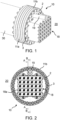
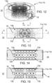
- the Figures 1 to 21 each show at least a portion of an optical fiber feedthrough 10 for a vacuum chamber 30.
- the optical fiber feedthrough 10 can thus, as exemplified in Figure 1 can be mounted on a vacuum chamber 30, for example by flanging it onto a (standardized) vacuum flange (e.g. CF flange) of the vacuum chamber 30.
- a vacuum flange e.g. CF flange
- the optical waveguide feedthrough 10 is preferably designed to pass a plurality of optical waveguides 1 between an interior of an evacuable vacuum chamber 30 and an (e.g. external) environment of the vacuum chamber 30.
- the optical waveguide feedthrough 10 can also be designed to guide light or optical signals through a pressure-tight wall or boundary of the vacuum chamber 30 (by means of the corresponding optical waveguides 1).
- the optical fiber feedthrough 10 has at least one holding flange 11a, 11b, having a plurality of through openings 12a, 12b, each of which is provided with a sealing receptacle 13a, 13b and at least one sealing element 14a, 14b, as well as at least one pressure device 15a, 15b.
- the at least one retaining flange 11a, 11b can be designed for fastening to the vacuum chamber 30, preferably in a pressure-tight manner.
- the at least one retaining flange 11a, 11b can be designed as a CF flange in accordance with ISO 3669:2017.
- the at least one retaining flange 11a, 11b can have a sealing surface (not expressly shown) which can be designed to correspond to a sealing surface of the vacuum flange of the vacuum chamber 30.
- the sealing surfaces of the at least one retaining flange 11a, 11b can, for example, be designed to accommodate a seal (e.g. in the form of an O-ring) and/or include a cutting edge (not shown).
- the at least one retaining flange 11a, 11b or its sealing surface can be designed to accommodate a metal sealing ring (e.g. copper sealing ring) into which the cutting edge of the at least one retaining flange 11a, 11b is pressed when the at least one retaining flange 11a, 11b is mounted on the vacuum chamber 30.
- a metal sealing ring e.g. copper sealing ring
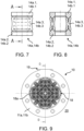
- the at least one retaining flange 11a, 11b for fastening to the vacuum chamber 30 can have a retaining flange hole circle for receiving fastening elements 2 (e.g. threaded bolts) (see e.g. Figures 1-3 ).
- the holding flange hole circle can be designed to correspond to a vacuum flange hole circle of the vacuum flange of the vacuum chamber 30. Accordingly, a number and arrangement of holes in the holding flange hole circle of the at least one holding flange 11a, 11b can correspond to a number and arrangement of holes in the vacuum flange hole circle of the vacuum flange of the vacuum chamber 30.
- the optical fiber feedthrough 10 can be fixed to the vacuum chamber 30.
- the at least one holding flange 11a, 11b has a plurality of through openings 12a, 12b (e.g. in the form of through holes), which preferably serve to accommodate the optical waveguides 1 (cf. e.g. Figures 3, 4 and 5 ).
- the through-openings 12a, 12b or their respective opening cross-section can each be adapted to a shape, size and/or contour of the optical waveguide 1 to be accommodated or accommodated.
- the number of through-openings 12a, 12b can vary depending on the flange size.
- the optical waveguide feedthrough 10 can have at least thirty, preferably at least sixty, through-openings 12a, 12b or optical waveguide feedthroughs for 1500 ⁇ m optical waveguides.
- the optical fiber feedthrough 10 can, for example, have at least thirty-five through-openings 12a, 12b or optical fiber feedthroughs for 470 ⁇ m optical fibers.
- the through-openings 12a, 12b can (completely) penetrate the at least one holding flange 11a, 11b. Accordingly, the through-openings 12a, 12b can connect the interior of the vacuum chamber 30 and the (e.g. external) environment of the vacuum chamber 30 to one another.
- the through-openings 12a, 12b are each designed to receive (e.g. pressure-tight) one optical waveguide 1 of the plurality of optical waveguides 1.
- One of the optical waveguides 1 can thus be received and/or arranged in the respective through-openings 12a, 12b.
- the optical waveguides 1 can be guided through the at least one holding flange 11a, 11b by means of the through-openings 12a, 12b.
- the optical waveguide feedthrough 10 together with the corresponding optical waveguides 1 can form an optical waveguide arrangement 20.
- each of the through openings 12a, 12b has a seal receptacle 13a, 13b and a sealing element 14a, 14b (see e.g. Figure 4 ).
- the optical fiber feedthrough 10 can comprise a plurality of sealing receptacles 13a, 13b and a plurality of sealing elements 14a, 14b.
- each of the sealing elements 14a, 14b is arranged in one of the sealing receptacles 13a, 13b, preferably for the pressure-tight reception of the optical fiber 1 guided through the respective through-openings 12a, 12b.
- the respective sealing receptacles 13a, 13b can be designed as a section of the respective through-openings 12a, 12b.
- the sealing receptacles 13a, 13b or the corresponding sections have a wider (opening) cross-section compared to the rest of the through-opening 12a, 12b.
- the sealing elements 14a, 14b can be designed, for example, as sealing rings and/or each comprise a sealing ring (see, for example, Figures 4 and 6 ).
- the sealing elements 14a, 14b or sealing rings can be made of an elastomer (such as Viton) and/or a metal alloy.
- the sealing elements 14a, 14b can have a circumferentially closed and/or annular (e.g. circular) shape.
- the sealing elements 14a, 14b can have a solid cross-section or be made of a solid material.
- the sealing elements 14a, 14b can be designed as O-rings.
- the sealing elements 14a, 14b can also be designed as C-rings.
- the sealing elements 14a, 14b can also be designed in several parts.
- the sealing elements 14a, 14b can have two (e.g. metallic) end sections 14a.1, 14a.2, 14b.1, 14b.2 and one (e.g. flexible) sealing sleeve 14a.3, 14b.3 (cf. Figures 7 and 8 ).
- the end sections 14a.1, 14a.2, 14b.1, 14b.2 can each be ring-shaped and/or have a closed shape. Parts of the end sections 14a.1, 14a.2, 14b.1, 14b.2 can be wedge-shaped and/or tapered.
- the wedge-shaped and/or tapered parts preferably protrude from the end sections 14a.1, 14a.2, 14b.1, 14b.2.
- the end sections 14a.1, 14a.2, 14b.1, 14b.2 can each be designed as a ring (e.g. metal ring) with a flat top side and a wedge-shaped and/or tapered bottom side.
- the end sections 14a.1, 14a.2, 14b.1, 14b.2 serve to distribute (e.g. evenly) an external pressure load on the sealing sleeve 14a.3, 14b.3.
- the end sections 14a.1, 14a.2, 14b.1, 14b.2 can also be referred to as stamps in this context.
- the sealing sleeve 14a.3, 14b.3 is preferably arranged between the two end sections 14a.1, 14a.2, 14b.1, 14b.2.
- the two end sections 14a.1, 14a.2, 14b.1, 14b.2 can thus be connected to one another via the sealing sleeve 14a.3, 14b.3.
- the sealing sleeve 14a.3, 14b.3 can be deformable (e.g. elastically) and/or flexible.
- the sealing sleeve 14a.3, 14b.3 can be made of polytetrafluoroethylene.
- the sealing sleeve 14a.3, 14b.3 it is also possible for the sealing sleeve 14a.3, 14b.3 to be made of metal or a metal alloy.
- the sealing sleeve 14a.3, 14b.3 can be made of stainless steel and/or stainless steel-copper and can optionally have a silver coating. Furthermore, the sealing sleeve 14a.3, 14b.3 can have a substantially X-shaped cross-section (e.g. profile cross-section).
- the two end sections 14a.1, 14a.2, 14b.1, 14b.2, preferably their wedge-shaped and/or tapered parts, can each engage in notches formed by legs of the X-shaped cross-section. Accordingly, each of the two end sections 14a.1, 14a.2, 14b.1, 14b.2 can rest against the sealing sleeve 14a.3, 14b.3 or be in direct mechanical contact, preferably via several (e.g.
- the sealing sleeve 14a.3, 14b.3 can be spread apart transversely to the axial direction (e.g. radially).
- the sealing sleeve 14a.3, 14b.3 can be designed to deform inwards and outwards (e.g. elastically) due to the axial pressure of the two end sections 14a.1, 14a.2, 14b.1, 14b.2.
- the optical fiber feedthrough 10 further comprises a pressure device 15a, 15b (see e.g. Figures 3, 4 and 5 ).
- This can be connected to the at least one retaining flange 11a, 11b (e.g. detachably).
- the pressure device 15a, 15b can be screwed to the at least one retaining flange 11a, 11b and/or fixed in another force-fitting and/or form-fitting manner.
- the pressure device 15a, 15b is designed to compress the sealing elements 14a, 14b axially along the respective through-openings 12a, 12b.
- the pressure device 15a, 15b can be designed to exert a clamping and/or pressure force on the sealing elements 14a, 14b that is oriented along the respective through-openings 12a, 12b.
- the pressure device 15a, 15b is designed to apply an adjustable (axial) clamping and/or pressure force (e.g. via the screw connection with the at least one holding flange 11a, 11b) to the Sealing elements 14a, 14b.
- the clamping and/or pressure force which can also be referred to as contact force, can be directed into the interior of the at least one holding flange 11a, 11b.
- the axial compression can induce radial expansion in the sealing elements 14a, 14b, preferably in order to thereby clamp the respective optical waveguides 1 (accommodated in the through-openings 12a, 12b) radially or circumferentially.
- the pressure device 15a, 15b can comprise, for example, a pressure plate 15a.1, 15b.1 (e.g. a steel plate) which can be fastened (e.g. detachably) to the at least one holding flange 11a, 11b (cf. e.g. Figures 3, 4 and 5 ).
- the pressure plate 15a.1, 15b.1 can be screwed to at least one holding flange 11a, 11b by means of several cylinder head screws.
- the pressure plate 15a.1, 15b.1 is preferably designed to exert the contact pressure (simultaneously) on several of the sealing elements 14a, 14b and/or to distribute the contact pressure as evenly as possible across several of the sealing elements 14a, 14b.
- the pressure plate 15a.1, 15b.1 can be made of metal or a metal alloy.
- the pressure plate 15a.1, 15b.1 can comprise aluminum, stainless steel, steel, brass and/or copper. Additionally or alternatively, it is also possible for the pressure plate 15a.1, 15b.1 to be made of ceramic, PEEK and/or Vespel.
- the pressure plate 15a.1, 15b.1 can have a plurality of through holes.
- the through holes can be used to guide the plurality of optical waveguides 1 or the optical waveguides 1 can be accommodated in the through holes.
- the plurality of through holes of the pressure plate 15a.1, 15b.1 can be aligned with the plurality of through openings 12a, 12b of the at least one holding flange 11a, 11b.
- the through holes of the pressure plate 15a.1, 15b.1 and the through openings 12a, 12b of the at least one holding flange 11a, 11b can be aligned in pairs, preferably in such a way that one of the optical waveguides 1 can be guided in a straight line through one of the through holes and one of the through openings 12a, 12b.
- the pressure device 15a, 15b can comprise a plurality of intermediate sleeves 15a.2, 15b.2 (cf. e.g. Figure 4 ).
- the intermediate sleeves 15a.2, 15b.2 can each be made of metal and/or a metal alloy.
- the intermediate sleeves 15a.2, 15b.2 can be made of brass and/or stainless steel.
- the intermediate sleeves 15a.2, 15b.2 are used to transfer the clamping and/or pressure force from the pressure plate 15a, 15b to the respective Sealing elements 14a, 14b.
- one of the intermediate sleeves 15a.2, 15b.2 can be arranged in one of the through openings 12a, 12b.
- each of the intermediate sleeves 15a.2, 15b.2 can thus be arranged between the pressure plate 15a.1, 15b.1 and one of the sealing elements 14a, 14b.
- each of the intermediate sleeves 15a.2, 15b.2 can have a first end that is supported on one of the sealing elements 14a, 14b, and a second end that is supported on the pressure plate 15a.1, 15b.1.
- each of the intermediate sleeves 15a.2, 15b.2 can have a bevel 15f (e.g. at its first end) (cf. Figure 6 ).
- each of the intermediate sleeves 15a.2, 15b.2 can be bevelled (e.g. at its first end).
- the respective surfaces against which the respective sealing elements 14a, 14b (on the respective intermediate sleeves 15a.2, 15b.2) rest can be enlarged by means of the corresponding bevels 15f. Furthermore, the respective number of sealing surfaces can be reduced (e.g. from four to three) by means of the respective bevels 15f. Additionally or alternatively, it is also possible for the through openings 12a, 12b and/or the sealing receptacles 13a, 13b to have corresponding bevels or bevelled areas into which, for example, the sealing elements 14a, 14b can be pressed or are pressed.
- the optical fiber feedthrough 10 and/or the pressure device 15a, 15b can further comprise a plurality of further sealing elements 14b' (cf. e.g. Figure 4 ).
- Each of the through-openings 12a, 12b is provided with one of the further sealing elements 14b' of the plurality of further sealing elements 14b'.
- each of the through-openings 12a, 12b can have a further sealing element 14b' in addition to the sealing element 14a, 14b.
- each of the further sealing elements 14b' is arranged in one of the sealing receptacles 13a, 13b, preferably for the pressure-tight reception of the optical waveguide 1 guided through the respective through-openings 12a, 12b.
- the further sealing elements 14b' can also have the features of the sealing elements 14a, 14b.
- the additional sealing elements 14b' can also be made from an elastomer (such as Viton) and/or from a metal alloy and/or be designed as O-rings and/or C-rings.
- the additional sealing elements 14b' can be designed in the same way as the sealing elements 14a, 14b.
- the sealing elements 14a, 14b and the additional sealing elements 14b' can be identical parts.
- the additional sealing elements 14b' and the sealing elements 14a, 14b can also be designed differently, e.g. made from different materials.
- the optical fiber feedthrough 10 and/or the pressure device 15a, 15b can have a plurality of further intermediate sleeves 15b.2' (cf. e.g. Figure 4 ).
- the through openings 12a, 12b can each be provided with one of the further intermediate sleeves 15b.2' of the plurality of further intermediate sleeves 15b.2'.
- each of the through openings 12a, 12b can have a further intermediate sleeve 15b.2' in addition to the intermediate sleeve 15b.2.
- the further intermediate sleeves 15b.2' can each be arranged between a sealing element 14a, 14b and a further sealing element 14b'.
- each of the further intermediate sleeves 15b.2' can be supported on one of the sealing elements 14a, 14b and one of the further sealing elements 14b'.
- the further intermediate sleeves 15b.2' can basically have the features of the intermediate sleeves 15a.2, 15b.2, for example they can be made of metal and/or a metal alloy and/or each have a (further) bevel 15f'.
- the further intermediate sleeves 15b.2' and the intermediate sleeves 15a.2, 15b.2 can be designed the same or as identical parts.
- the further intermediate sleeves 15b.2' and the intermediate sleeves 15a.2, 15b.2 can also be designed differently, for example they can be made of different materials.
- the at least one retaining flange 11a, 11b has a first retaining flange 11a (e.g. in the form of a CF flange) and a second retaining flange 11b (e.g. in the form of a CF flange) (see e.g. Figures 1 to 5 ).
- the at least one retaining flange 11a, 11b can be designed as a double flange.
- the first retaining flange 11a and the second retaining flange 11b can be fastened to one another (e.g. detachably) (e.g. screwed together).
- the first retaining flange 11a can comprise a first bolt circle with a plurality of first holes and the second retaining flange 11b can comprise a second bolt circle with a plurality of second holes.
- a number and arrangement of the first holes of the first bolt circle corresponds to a number and arrangement of the second holes of the second bolt circle.
- the first and second holes can, for example, be arranged in pairs in alignment with one another.
- the respective first holes of the first retaining flange 11a can each have an (internal) thread. Furthermore, the respective second holes of the second retaining flange 11a can each have a contact surface for a head of a screw element 3 (e.g. for a head of a cylinder head screw) (cf. Figure 5 ).
- the first retaining flange 11a and the second retaining flange 11b can be connected or screwed together by means of screw elements 3 guided through the respective second holes and screwed into the respective threads of the first holes.
- first and second retaining flanges 11a, 11b can also each have corresponding sealing surfaces.
- first retaining flange 11a can have a first sealing surface and the second retaining flange 11b can have a second sealing surface.
- the first sealing surface and second sealing surface can each be designed to accommodate a double flange seal (e.g. in the form of a metal sealing ring) and/or each have a cutting edge for pressing into the double flange seal or a double flange seal.
- the first and second retaining flanges 11a, 11b can be connected to one another (e.g. pressure-tight) via a double flange seal (e.g. resting on the respective sealing surfaces).
- the optical fiber feedthrough 10 can further comprise a double flange seal which is arranged between the first and second holding flanges 11a, 11b and into which the respective cutting edges of the first and second holding flanges 11a, 11b are preferably pressed.
- the first holding flange 11a and the second holding flange 11b can further have fastening holes for fastening the first and second holding flanges 11a, 11b to the vacuum chamber 30.
- the first holding flange 11a can have first fastening holes (e.g. completely penetrating the first holding flange 11a) (e.g. threadless through holes) and the second holding flange 11b can have second fastening holes (e.g. completely penetrating the second holding flange 11b) (e.g. threadless through holes).
- the first and second fastening holes can be arranged in pairs in alignment with one another.
- the first and second fastening holes can form the holding flange hole circle for fastening the at least one holding flange 11a, 11b to the vacuum chamber 30.
- the first fastening holes can be arranged between two of the first holes of the first bolt circle and the second fastening holes can be arranged between two of the second holes of the second bolt circle (cf. Figure 1 ).
- the first retaining flange 11a and the second retaining flange 11b can be spaced apart from one another at least in sections. Accordingly, an (e.g. evacuatable) intermediate space 16 can be arranged or provided between the first retaining flange 11a and the second retaining flange 11b (cf. e.g. Figures 3-5 ). This intermediate space 16 can be delimited at least in sections by the first and second retaining flanges 11a, 11b. Furthermore, the intermediate space 16 can be delimited by the double flange seal. The intermediate space 16 can also not be rotationally symmetrical. For example, an upper part of the intermediate space 16 (in the axial direction) can have a smaller extent than a lower part of the intermediate space 16.
- the intermediate space 16 can be evacuated (e.g. by means of a vacuum pump, in particular a rotary vane pump).
- the intermediate space 16 can be evacuated to a pressure below 0.1 mbar, preferably below 0.01 mbar.
- the first retaining flange 11a and/or the second retaining flange 11b can comprise a pumping opening with a nozzle 19 for connecting a vacuum pump.
- the vacuum pump can be fluidically connected to the intermediate space 16 via the pumping opening or the nozzle 19.
- the nozzle 19 is preferably designed as a KF nozzle (for receiving a KF seal).
- the plurality of through openings 12a, 12b can have a (first) plurality of first through openings 12a and a (second) plurality of second through openings 12b.
- the (first) plurality of first through openings 12a can be arranged on the first holding flange 11a or the first holding flange 11a can have the (first) plurality of first through openings 12a.
- the (second) plurality of second through openings 12b can be arranged on the second holding flange 11b or the second holding flange 11b can have the (second) plurality of second through openings 12b.
- the first through-openings 12a and the second through-openings 12b can be aligned with one another (e.g. in alignment).
- the first through-openings 12a of the first holding flange 11a and the second through-openings 12b of the second holding flange 11b can be arranged in pairs in alignment with one another, preferably for the straight-line reception of one of the optical waveguides 1.
- the first through-openings 12a of the first holding flange 11a and the second through-openings 12b of the second holding flange 11b can be separated from one another and/or spaced apart from one another by the intermediate space 16.
- an optical waveguide 1 accommodated in the at least one holding flange 11a, 11b can initially extend through one of the first through-openings 12a of the first holding flange 11a, then through the intermediate space 16 and finally through one of the second through-openings 12a of the second holding flange 11b.
- the respective optical waveguides 1 have a metal sheath 1a, 1b in the region of the first and second holding flange 11a, 11b or in the regions in which the respective optical waveguides 1 are guided through the first and second through-opening 12a, 12b.
- Each of the optical waveguides 1 accommodated in the optical waveguide arrangement 20 can thus have a, preferably two-part, metal jacket 1a, 1b.
- each of the optical waveguides 1 can have a first metal jacket 1a (e.g. arranged in the area of the first holding flange 11a) and a second metal jacket 1b (e.g. arranged in the area of the second holding flange 11b).
- the first and second metal jackets 1a, 1b can be spaced apart from one another by an uncoated section of the optical waveguide 1, which is preferably arranged in the area of the intermediate space 16.
- the first and second metal jackets 1a, 1b can be glued to the respective optical waveguide 1 (e.g. using epoxy resin). In this case, it is preferable to ensure that the adhesive does not form an enveloping layer in the intermediate space 16 or on the uncoated section of the optical waveguide 1 due to the short distance between the two metal jackets 1a and 1b.
- the first and second metal jackets 1a, 1b can also be soldered to a metal coating (e.g. in sections) of the respective optical waveguides 1.
- the first and second metal jackets 1a, 1b can each have an inner diameter of 3 mm.
- the first and/or second metal jackets 1a, 1b can be conically tapered (e.g. at a respective end region) and/or have a bevel (e.g. of 60°).
- Each of the first through-openings 12a can be provided with a first seal receptacle 13a or have a first seal receptacle 13a.
- the second through-openings 12b can be provided with a second seal receptacle 13b or have a second seal receptacle 13b.
- the plurality of seal receptacles 13a, 13b can have a (first) plurality of first seal receptacles 13a and a (second) plurality of second seal receptacles 13b.
- the first seal receptacles 13a can each be arranged and/or formed in one of the first through-openings 12a of the first holding flange 11a.
- the second seal receptacles 13b can each be arranged and/or formed in one of the second through-openings 12b of the second holding flange 11b.
- a first sealing element 14a can be arranged and/or accommodated in each of the first sealing receptacles 13a (cf. Figure 4 ). Accordingly, a second sealing element 14b can be arranged and/or accommodated in each of the second sealing receptacles 13b.
- the plurality of sealing elements 14a, 14b can thus have a (first) plurality of first sealing elements 14a and a (second) plurality of second sealing elements 14b.
- the first sealing elements 14a and second sealing elements 14b can be designed as The first sealing elements 14a and the second sealing elements 14b can also be designed differently.
- the first sealing elements 14a can each be made of metal and the second sealing elements 14b can each be made of Viton.
- first sealing elements 14a can each be designed as (e.g. one-piece) sealing rings (e.g. sealing O-rings) and the second sealing elements 14b can each be designed in multiple parts (e.g. each having two (second) end sections 14b.1, 14b.2 and a (second) sealing sleeve 14b.3).
- first sealing elements 14a can each be designed as (e.g. one-piece) sealing rings (e.g. sealing O-rings) and the second sealing elements 14b can each be designed in multiple parts (e.g. each having two (second) end sections 14b.1, 14b.2 and a (second) sealing sleeve 14b.3).
- the at least one pressure device 15a, 15b can have a first pressure device 15a and a second pressure device 15b.
- the first pressure device 15a can be assigned to the first holding flange 11a and/or fastened to the first holding flange 11a.
- the first pressure device 15a can be arranged (at least in sections) on an (inner) side of the first holding flange 11a facing the interior of the vacuum chamber 30.
- the second pressure device 15b can be assigned to the second holding flange 11b and/or fastened to the second holding flange 11b.
- the second pressure device 15b can be arranged (at least in sections) on an (outer) side of the second holding flange 11b facing the environment.
- the first and second pressure devices 15a, 15b can each have the components already described above, with the addition “first” indicating that the corresponding component is arranged on the first retaining flange 11a or is associated with it, and the addition “second” indicating that the corresponding component is arranged on the second retaining flange 11b or is associated with it. To avoid repetition, individual aspects will therefore only be discussed again below as examples.
- the first pressure device 15a can have a first pressure plate 15a.1.
- the first pressure plate 15a.1 can be attached to the first holding flange 11a (e.g. detachably) and/or have a plurality of first through holes for the plurality of optical fibers 1.
- the second pressure device 15b can also have a second pressure plate 15b.1.
- the second pressure plate 15b.1 can be attached to the second holding flange 11b (e.g. detachably) and/or have a plurality of second through holes for the plurality of optical fibers 1.
- the first and second through holes are preferably arranged in pairs. be aligned so that each of the optical waveguides 1 can be or is guided in a straight line through one of the first through-holes and one of the second through-holes.
- the first pressure device 15a can have a first plurality of first intermediate sleeves 15a.2 (cf. Figure 4 ).
- one of the first intermediate sleeves 15a.2 can be arranged in one of the first through openings 12a.
- each of the first intermediate sleeves 15a.2 can be arranged between the first pressure plate 15a.1 and one of the first sealing elements 14a.
- the second pressure device 15b can also have a second plurality of second intermediate sleeves 15b.2.
- One of the second intermediate sleeves 15b.2 can be arranged in one of the second through openings 12b.
- each of the second intermediate sleeves 15b.2 can be arranged between the second pressure plate 15b.1 and one of the second sealing elements 14b.
- the first pressure device 15a can have a plurality of further first sealing elements (not shown) and/or a plurality of further first intermediate sleeves (not shown).
- each of the first through openings 12a can be provided with one of the further first sealing elements and/or one of the further first intermediate sleeves.
- the second pressure device 15b can also have a plurality of further second sealing elements 14b' (e.g. O-rings and/or C-rings) and/or a plurality of further second intermediate sleeves 15b.2'.
- Each of the second through openings 12a can be provided with one of the further second sealing elements 14b' and/or one of the further second intermediate sleeves 15b.2'.
- the double flange can be designed as an integral one-piece.
- the at least one retaining flange 11a, 11b or the double flange can be manufactured, for example, using 3D printing technology or additive manufacturing.
- the first and second retaining flange 11a, 11b can thus be manufactured "virtually from one cast" and/or connected to one another as an integral one-piece.
- the first and second hole circles and the double flange seal can then be omitted or not present.
- the at least one retaining flange 11a, 11b is designed as an integral one-piece.
- the gap 16 is still present.
- the at least one retaining flange 11a, 11b be formed in one piece and have an evacuable intermediate space 16, which is preferably formed within the at least one holding flange 11a, 11b.
- the first through openings 12a of the at least one holding flange 11a and the second through openings 12b of the at least one holding flange 11a can be separated from one another and/or spaced apart from one another via this intermediate space 16.
- the plurality of waveguide couplings 18a of the coupling device 18 can be arranged offset from one another in several (eg two) planes.
- a first subset (eg twenty) of the plurality of waveguide couplings 18a can have a smaller distance from the second pressure plate 15b.1 than a second subset (eg sixteen) of the plurality of waveguide couplings 18a.
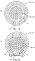
- the at least one holding flange 11a, 11b can have a cooling channel 112 (cf. Figures 17-21 ).
- the cooling channel 112 can be flowed through by a preferably liquid cooling medium (e.g. water).
- a preferably liquid cooling medium e.g. water
- corresponding connections for connecting cooling lines can be present on the at least one holding flange 11a, 11b, wherein the connections are fluidically connected to the cooling channel 112.
- the cooling channel 112 can be arranged inside the at least one holding flange 11a, 11b or inside the first and/or second holding flange 11a.
- the cooling channel 112 can be introduced (e.g. printed) into the at least one holding flange 11a, 11b during additive manufacturing, for example.
- the cooling channel 112 can have a diameter of approximately 1.5 mm at the seal receptacles 13a, 13b.
- the cooling channel 112 can run in a meandering manner within the at least one retaining flange 11a, 11b and/or branch into a cooling channel line network (cf. Figure 18 ).
- the cooling channel line network can have two (e.g. curved) main cooling channels that are fluidically connected to one another via several (e.g. meandering) cooling channel branch lines.
- the active cooling of the sealing points makes it possible to advantageously use low-melting materials (e.g. soft solder) for sealing or sheathing the optical fibers 1, which would otherwise be damaged during an assembly and/or baking process.
- the optical waveguide feedthrough 10 - regardless of the specific design of the at least one holding flange 11a, 11b - further comprise a tube section 111 which extends away from the optical waveguide feedthrough 10 (e.g. in the direction of the vacuum chamber 30) (cf. Figures 3 and 5 ).
- the pipe section 111 can have a first end region that is connected to the first holding flange 11a and/or the first pressure plate 15a.1 of the first holding flange 11a (e.g. detachably), and have a free second end region.
- the pipe section 111 can surround the first pressure plate 15a.1 and/or the optical fibers 1 at least in sections (e.g. circumferentially). Accordingly, the pipe section 111 can serve to protect the optical fibers 1 during assembly/dismantling.
- the optical fiber feedthrough 10 can have a support device 17 (cf. Figures 3 and 5 ).
- the support device 17 preferably serves for (additional) support and/or storage of the optical waveguides 1.
- the support device 17 can be arranged at a distance from the first holding flange 11a on the side of the vacuum chamber 30.
- the support device 17 is therefore preferably at a greater distance from the second holding flange 11b than from the first holding flange 11a.
- the support device 17 can, for example, be designed as a support plate and/or be made of polyetheretherketone.
- the support device 17 can be connected via the pipe section 111 to the first holding flange 11a and/or to the first pressure plate 15a.1 of the first holding flange 11a.
- the support device 17 can be screwed to the pipe section 111 (e.g. in the area of rounded corners of the support device 17). Accordingly, the pipe section can surround the support device 17 at least in sections (e.g. on the circumference).
- the support device 17 can have a plurality of holding openings 17a for receiving the optical waveguides 1.
- the holding openings 17a are preferably aligned with the first through openings 12a of the first holding flange 11a and the second through openings 12b of the second holding flange 11b.
- the respective optical waveguides 1 can each extend in a straight line through one of the holding openings 17a of the support device 17, one of the first through openings 12a of the first holding flange 11a and one of the second through openings 12b of the second holding flange 11b.
- movements of the optical waveguides 1 or mechanical stresses in the adhesive area of the optical waveguides 1 can be avoided as far as possible in an advantageous manner.
- the optical fiber feedthrough 10 can have a coupling device 18 (e.g. an FC connector coupling device) (cf. Figures 1 to 5 ).
- the coupling device 18 serves to connect or couple the optical waveguides 1 with (external) further optical waveguides.
- the coupling device 18 can be arranged on the side surrounding the vacuum chamber 30 at a distance from the second holding flange 11b.
- the Coupling device 18 therefore has a greater distance from the first holding flange 11a than from the second holding flange 11b.
- the coupling device 18 can be fastened to the second holding flange 11b and/or to the pressure plate 15b.1 of the second holding flange 11b via an extension (e.g.
- the coupling device 18 can also have a plurality of waveguide couplings 18a (e.g. in the form of corresponding sockets) for connecting the external optical fibers (e.g. for connecting external optical fiber plugs).
- the coupling device 18 can have a holding plate to which the waveguide couplings 18a are fastened (e.g. by means of countersunk screws).
- the waveguide couplings 18a can each be designed as FC couplings and/or to form a plug connection with FC plugs.
- the optical waveguides 1 can each have an FC connector, which is connected to the respective waveguide couplings 18a, for example on a side of the coupling device 18 facing the vacuum chamber 30 or the at least one holding flange 11a, 11b.
- the respective waveguide couplings 18a can be connected to FC connectors of the external optical waveguides on a side of the coupling device 18 facing the environment.
- the waveguide couplings 18a are preferably aligned with the first through openings 12a of the first holding flange 11a, the second through openings 12b of the second holding flange 12b and/or the holding openings 17a of the support device 17.
Landscapes
- Physics & Mathematics (AREA)
- General Physics & Mathematics (AREA)
- Optics & Photonics (AREA)
- Light Guides In General And Applications Therefor (AREA)
Applications Claiming Priority (1)
| Application Number | Priority Date | Filing Date | Title |
|---|---|---|---|
| DE102023121227.3A DE102023121227B3 (de) | 2023-08-09 | 2023-08-09 | Lichtwellenleiter-Durchführung für eine Vakuumkammer, Lichtwellenleiter-Anordnung und Verfahren zur Durchführung einer Vielzahl von Lichtwellenleitern |
Publications (1)
| Publication Number | Publication Date |
|---|---|
| EP4506743A1 true EP4506743A1 (fr) | 2025-02-12 |
Family
ID=92208840
Family Applications (1)
| Application Number | Title | Priority Date | Filing Date |
|---|---|---|---|
| EP24192311.9A Pending EP4506743A1 (fr) | 2023-08-09 | 2024-08-01 | Traversée de guide d'ondes optiques pour chambre à vide |
Country Status (3)
| Country | Link |
|---|---|
| US (1) | US20250052974A1 (fr) |
| EP (1) | EP4506743A1 (fr) |
| DE (1) | DE102023121227B3 (fr) |
Citations (10)
| Publication number | Priority date | Publication date | Assignee | Title |
|---|---|---|---|---|
| BE898110A (fr) * | 1982-10-30 | 1984-02-15 | Ernst Vogelsang G M B H & Co K | Dispositif de fermeture terminale de caniveaux. |
| US5861577A (en) * | 1992-06-05 | 1999-01-19 | Hitachi Construction Machinery Co., Ltd. | Seal structure for member-passing-through hole bored in metal partition member |
| DE19756876A1 (de) * | 1997-12-19 | 1999-04-15 | Siemens Ag | Durchführung |
| US6633720B1 (en) * | 2001-03-30 | 2003-10-14 | Avanex Corporation | Hermetic seal feed-through assembly for optical fiber |
| US20040144555A1 (en) * | 2002-11-30 | 2004-07-29 | Valere Buekers | Longitudinally activated compression sealing device for elongate members and methods for using the same |
| US20080136170A1 (en) * | 2004-06-02 | 2008-06-12 | Gl Tool & Manufacturing Company Inc. | Bulkhead Connector |
| US10559408B2 (en) * | 2016-12-27 | 2020-02-11 | Asml Netherlands B.V. | Feedthrough device and signal conductor path arrangement |
| CN211180291U (zh) * | 2019-11-28 | 2020-08-04 | 中天海洋系统有限公司 | 一种分瓣式水密光连接器 |
| US10908377B1 (en) * | 2018-08-30 | 2021-02-02 | ARIA Technologies, Inc. | Microduct manifold fitting |
| DE112019006860T5 (de) | 2019-02-15 | 2021-11-25 | Kla Corporation | Lieferung von licht in eine vakuumkammer unter verwendung einer optischen faser |
Family Cites Families (1)
| Publication number | Priority date | Publication date | Assignee | Title |
|---|---|---|---|---|
| US9696505B2 (en) * | 2015-09-02 | 2017-07-04 | LGS Innovations LLC | Feedthrough assembly and method of assembling a feedthrough assembly |
-
2023
- 2023-08-09 DE DE102023121227.3A patent/DE102023121227B3/de active Active
-
2024
- 2024-08-01 EP EP24192311.9A patent/EP4506743A1/fr active Pending
- 2024-08-09 US US18/799,012 patent/US20250052974A1/en active Pending
Patent Citations (10)
| Publication number | Priority date | Publication date | Assignee | Title |
|---|---|---|---|---|
| BE898110A (fr) * | 1982-10-30 | 1984-02-15 | Ernst Vogelsang G M B H & Co K | Dispositif de fermeture terminale de caniveaux. |
| US5861577A (en) * | 1992-06-05 | 1999-01-19 | Hitachi Construction Machinery Co., Ltd. | Seal structure for member-passing-through hole bored in metal partition member |
| DE19756876A1 (de) * | 1997-12-19 | 1999-04-15 | Siemens Ag | Durchführung |
| US6633720B1 (en) * | 2001-03-30 | 2003-10-14 | Avanex Corporation | Hermetic seal feed-through assembly for optical fiber |
| US20040144555A1 (en) * | 2002-11-30 | 2004-07-29 | Valere Buekers | Longitudinally activated compression sealing device for elongate members and methods for using the same |
| US20080136170A1 (en) * | 2004-06-02 | 2008-06-12 | Gl Tool & Manufacturing Company Inc. | Bulkhead Connector |
| US10559408B2 (en) * | 2016-12-27 | 2020-02-11 | Asml Netherlands B.V. | Feedthrough device and signal conductor path arrangement |
| US10908377B1 (en) * | 2018-08-30 | 2021-02-02 | ARIA Technologies, Inc. | Microduct manifold fitting |
| DE112019006860T5 (de) | 2019-02-15 | 2021-11-25 | Kla Corporation | Lieferung von licht in eine vakuumkammer unter verwendung einer optischen faser |
| CN211180291U (zh) * | 2019-11-28 | 2020-08-04 | 中天海洋系统有限公司 | 一种分瓣式水密光连接器 |
Also Published As
| Publication number | Publication date |
|---|---|
| DE102023121227B3 (de) | 2024-12-24 |
| US20250052974A1 (en) | 2025-02-13 |
Similar Documents
| Publication | Publication Date | Title |
|---|---|---|
| DE19738733C1 (de) | Steckverbinder für Koaxialkabel mit ringgewelltem Außenleiter | |
| DE69514934T2 (de) | Verbindung | |
| WO2007118548A1 (fr) | Corps d'étanchéité d'un manchon de câble | |
| DE102006038134A1 (de) | Plasmabrennerkopf, Plasmabrennerschaft und Plasmabrenner | |
| WO2006047907A1 (fr) | Fiche de cable coaxial et procede pour monter une fiche de ce type | |
| EP3329500B1 (fr) | Dispositif antidéflagrant pour traversée de boulon et son procédé de fabrication | |
| EP3876372B1 (fr) | Dispositif protégé contre les explosions | |
| EP1412668B1 (fr) | Raccord a sertir destine a des tuyaux | |
| DE102023121227B3 (de) | Lichtwellenleiter-Durchführung für eine Vakuumkammer, Lichtwellenleiter-Anordnung und Verfahren zur Durchführung einer Vielzahl von Lichtwellenleitern | |
| DE102015204689A1 (de) | Rohrverbindungssystem | |
| EP2434194A2 (fr) | Agencement de liaison pour relier des composants hydrauliques | |
| DE102012212023A1 (de) | Kabelverschraubung | |
| DE112019002787T5 (de) | Transferleitung, GCMS-Anordnung und Montagebaugruppe | |
| WO2024194093A1 (fr) | Ensemble de composants d'hydrogène, et récipient de gaz comprimé possédant un ensemble de composants d'hydrogène | |
| EP1950770B1 (fr) | Isolateur | |
| WO2022063364A1 (fr) | Dispositif pour guider une conduite à travers une paroi de manière étanche à la pression, et procédé de fabrication du dispositif | |
| EP0915191A2 (fr) | Appareillage pour faire un joint à vide entre deux corps en matériaux différents | |
| DE102022117201B3 (de) | Verbindungskörper, explosionsgeschützte Leitungsdurchführung und/oder Leitungseinführung sowie Verfahren zu deren Herstellung | |
| DE3300328A1 (de) | Doppelrueckschlagventil, vorzugsweise fuer vollisolierte, mit schwefelhexafluorid gefuellte schaltanlagen | |
| EP1245888B1 (fr) | Adaptateur de position pour des connections de tuyaux et câbles | |
| DE19743185A1 (de) | Vorrichtung zum Anschließen von Rohrleitungen | |
| DE4127968A1 (de) | Hochtemperaturbestaendige leitungsdurchfuehrung fuer einen druckbehaelter | |
| EP3171030B1 (fr) | Pompe à vide | |
| DE965863C (de) | Rohrverbinder | |
| DE102019119130A1 (de) | Vorrichtung zur Anbindung von zumindest einer elektrischen Leitung an ein Gehäuse sowie Verfahren zum Anbringen von zumindest einer elektrischen Leitung an ein Gehäuse |
Legal Events
| Date | Code | Title | Description |
|---|---|---|---|
| PUAI | Public reference made under article 153(3) epc to a published international application that has entered the european phase |
Free format text: ORIGINAL CODE: 0009012 |
|
| STAA | Information on the status of an ep patent application or granted ep patent |
Free format text: STATUS: THE APPLICATION HAS BEEN PUBLISHED |
|
| AK | Designated contracting states |
Kind code of ref document: A1 Designated state(s): AL AT BE BG CH CY CZ DE DK EE ES FI FR GB GR HR HU IE IS IT LI LT LU LV MC ME MK MT NL NO PL PT RO RS SE SI SK SM TR |
|
| STAA | Information on the status of an ep patent application or granted ep patent |
Free format text: STATUS: REQUEST FOR EXAMINATION WAS MADE |
|
| 17P | Request for examination filed |
Effective date: 20250618 |