EP4507108A1 - Batterie et dispositif électronique - Google Patents
Batterie et dispositif électronique Download PDFInfo
- Publication number
- EP4507108A1 EP4507108A1 EP23887621.3A EP23887621A EP4507108A1 EP 4507108 A1 EP4507108 A1 EP 4507108A1 EP 23887621 A EP23887621 A EP 23887621A EP 4507108 A1 EP4507108 A1 EP 4507108A1
- Authority
- EP
- European Patent Office
- Prior art keywords
- tabs
- battery
- battery cell
- connecting portion
- boss
- Prior art date
- Legal status (The legal status is an assumption and is not a legal conclusion. Google has not performed a legal analysis and makes no representation as to the accuracy of the status listed.)
- Granted
Links
Images


Classifications
-
- H—ELECTRICITY
- H01—ELECTRIC ELEMENTS
- H01M—PROCESSES OR MEANS, e.g. BATTERIES, FOR THE DIRECT CONVERSION OF CHEMICAL ENERGY INTO ELECTRICAL ENERGY
- H01M50/00—Constructional details or processes of manufacture of the non-active parts of electrochemical cells other than fuel cells, e.g. hybrid cells
- H01M50/50—Current conducting connections for cells or batteries
- H01M50/543—Terminals
- H01M50/552—Terminals characterised by their shape
- H01M50/553—Terminals adapted for prismatic, pouch or rectangular cells
- H01M50/557—Plate-shaped terminals
-
- H—ELECTRICITY
- H01—ELECTRIC ELEMENTS
- H01M—PROCESSES OR MEANS, e.g. BATTERIES, FOR THE DIRECT CONVERSION OF CHEMICAL ENERGY INTO ELECTRICAL ENERGY
- H01M10/00—Secondary cells; Manufacture thereof
- H01M10/42—Methods or arrangements for servicing or maintenance of secondary cells or secondary half-cells
-
- H—ELECTRICITY
- H01—ELECTRIC ELEMENTS
- H01M—PROCESSES OR MEANS, e.g. BATTERIES, FOR THE DIRECT CONVERSION OF CHEMICAL ENERGY INTO ELECTRICAL ENERGY
- H01M10/00—Secondary cells; Manufacture thereof
- H01M10/42—Methods or arrangements for servicing or maintenance of secondary cells or secondary half-cells
- H01M10/425—Structural combination with electronic components, e.g. electronic circuits integrated to the outside of the casing
-
- H—ELECTRICITY
- H01—ELECTRIC ELEMENTS
- H01M—PROCESSES OR MEANS, e.g. BATTERIES, FOR THE DIRECT CONVERSION OF CHEMICAL ENERGY INTO ELECTRICAL ENERGY
- H01M50/00—Constructional details or processes of manufacture of the non-active parts of electrochemical cells other than fuel cells, e.g. hybrid cells
- H01M50/50—Current conducting connections for cells or batteries
-
- H—ELECTRICITY
- H01—ELECTRIC ELEMENTS
- H01M—PROCESSES OR MEANS, e.g. BATTERIES, FOR THE DIRECT CONVERSION OF CHEMICAL ENERGY INTO ELECTRICAL ENERGY
- H01M50/00—Constructional details or processes of manufacture of the non-active parts of electrochemical cells other than fuel cells, e.g. hybrid cells
- H01M50/50—Current conducting connections for cells or batteries
- H01M50/502—Interconnectors for connecting terminals of adjacent batteries; Interconnectors for connecting cells outside a battery casing
- H01M50/519—Interconnectors for connecting terminals of adjacent batteries; Interconnectors for connecting cells outside a battery casing comprising printed circuit boards [PCB]
-
- H—ELECTRICITY
- H01—ELECTRIC ELEMENTS
- H01M—PROCESSES OR MEANS, e.g. BATTERIES, FOR THE DIRECT CONVERSION OF CHEMICAL ENERGY INTO ELECTRICAL ENERGY
- H01M50/00—Constructional details or processes of manufacture of the non-active parts of electrochemical cells other than fuel cells, e.g. hybrid cells
- H01M50/50—Current conducting connections for cells or batteries
- H01M50/531—Electrode connections inside a battery casing
- H01M50/533—Electrode connections inside a battery casing characterised by the shape of the leads or tabs
-
- H—ELECTRICITY
- H01—ELECTRIC ELEMENTS
- H01M—PROCESSES OR MEANS, e.g. BATTERIES, FOR THE DIRECT CONVERSION OF CHEMICAL ENERGY INTO ELECTRICAL ENERGY
- H01M50/00—Constructional details or processes of manufacture of the non-active parts of electrochemical cells other than fuel cells, e.g. hybrid cells
- H01M50/50—Current conducting connections for cells or batteries
- H01M50/531—Electrode connections inside a battery casing
- H01M50/536—Electrode connections inside a battery casing characterised by the method of fixing the leads to the electrodes, e.g. by welding
-
- H—ELECTRICITY
- H01—ELECTRIC ELEMENTS
- H01M—PROCESSES OR MEANS, e.g. BATTERIES, FOR THE DIRECT CONVERSION OF CHEMICAL ENERGY INTO ELECTRICAL ENERGY
- H01M50/00—Constructional details or processes of manufacture of the non-active parts of electrochemical cells other than fuel cells, e.g. hybrid cells
- H01M50/50—Current conducting connections for cells or batteries
- H01M50/543—Terminals
- H01M50/547—Terminals characterised by the disposition of the terminals on the cells
- H01M50/55—Terminals characterised by the disposition of the terminals on the cells on the same side of the cell
-
- H—ELECTRICITY
- H01—ELECTRIC ELEMENTS
- H01M—PROCESSES OR MEANS, e.g. BATTERIES, FOR THE DIRECT CONVERSION OF CHEMICAL ENERGY INTO ELECTRICAL ENERGY
- H01M50/00—Constructional details or processes of manufacture of the non-active parts of electrochemical cells other than fuel cells, e.g. hybrid cells
- H01M50/50—Current conducting connections for cells or batteries
- H01M50/572—Means for preventing undesired use or discharge
- H01M50/574—Devices or arrangements for the interruption of current
-
- H—ELECTRICITY
- H01—ELECTRIC ELEMENTS
- H01M—PROCESSES OR MEANS, e.g. BATTERIES, FOR THE DIRECT CONVERSION OF CHEMICAL ENERGY INTO ELECTRICAL ENERGY
- H01M50/00—Constructional details or processes of manufacture of the non-active parts of electrochemical cells other than fuel cells, e.g. hybrid cells
- H01M50/50—Current conducting connections for cells or batteries
- H01M50/572—Means for preventing undesired use or discharge
- H01M50/584—Means for preventing undesired use or discharge for preventing incorrect connections inside or outside the batteries
- H01M50/588—Means for preventing undesired use or discharge for preventing incorrect connections inside or outside the batteries outside the batteries, e.g. incorrect connections of terminals or busbars
-
- Y—GENERAL TAGGING OF NEW TECHNOLOGICAL DEVELOPMENTS; GENERAL TAGGING OF CROSS-SECTIONAL TECHNOLOGIES SPANNING OVER SEVERAL SECTIONS OF THE IPC; TECHNICAL SUBJECTS COVERED BY FORMER USPC CROSS-REFERENCE ART COLLECTIONS [XRACs] AND DIGESTS
- Y02—TECHNOLOGIES OR APPLICATIONS FOR MITIGATION OR ADAPTATION AGAINST CLIMATE CHANGE
- Y02E—REDUCTION OF GREENHOUSE GAS [GHG] EMISSIONS, RELATED TO ENERGY GENERATION, TRANSMISSION OR DISTRIBUTION
- Y02E60/00—Enabling technologies; Technologies with a potential or indirect contribution to GHG emissions mitigation
- Y02E60/10—Energy storage using batteries
Definitions
- the present application relates to the field of batteries, and in particular to a battery and an electronic device.
- lithium-ion batteries have the advantages of large capacity, small bulk and light weight, and are green and environmentally friendly. They have been widely used in industries such as digital electronic products and electric vehicles.
- a battery protection board is generally provided on a lithium-ion battery for monitoring and protection.
- fast charging technology becomes more and more popular, overcurrent-related requirements for batteries and protection boards are getting higher and higher.
- the size of the protection board is set to be relatively large accordingly.
- the present application provides a battery and an electronic device, aiming to solve the technical problem in the related art that the battery life of the electronic device would be affected due to relatively small battery capacity.
- the present application provides a battery, including a battery cell, a connecting member and a protection board assembly, where the battery cell includes a battery cell body and two tabs connected to the battery cell body, the connecting member includes two connecting tabs and a connecting portion connecting the two connecting tabs, where one of the connecting tabs is connected to and is electrically conducted with one of the tabs to form a composite tab; the composite tab and the other one of the tabs are both connected to the protection board assembly to form a first loop; the other one of the connecting tabs and the other one of the tabs are both connected to the protection board assembly to form a second loop.
- the connecting portion includes a connecting portion body and a boss which are integrally formed, the connecting portion body is connected to the two connecting tabs, and the boss is connected to the battery cell body.
- the boss is located at a position on the connecting portion body corresponding to any one of the two connecting tabs, and is located on a side of the connecting portion body close to the battery cell body.
- the boss is located on the connecting portion body between the two connecting tabs;
- the one of the connecting tabs is stacked and connected with the one of the tabs to form the composite tab.
- the protection board assembly includes a circuit board, a first conductive member, a second conductive member and a third conductive member, the first conductive member is connected to the other composite tab, the second conductive member is connected to the other one of the tabs, and the third conductive member is connected to the other one of the connecting tabs.
- the circuit board, the first conductive member, the second conductive member, the composite tab and the other one of the tabs form the first loop;
- the circuit board, the second conductive member, the third conductive member, the other one of the tabs, and the other one of the connecting tabs form the second loop.
- an insulating layer is further included, where the insulating layer covers both sides of the connecting portion, and along an extending direction of the connecting portion, an edge of the insulating layer protrudes beyond an edge of the connecting portion.
- the edge of the insulating layer protrudes beyond the edge of the connecting portion by a size of 0.2 mm to 1.0 mm.
- an extending direction of the connecting tab and an extending direction of the connecting portion body intersect with each other, and a first notch is provided at a corner of a connection position between the connecting tab and the connecting portion body;
- the connecting member is a flexible connecting member, and a portion of the connecting member is bent and connected to the battery cell body.
- the portion of the connecting member is bent and enters a deep pit surface of a top sealing of the battery cell body; or, the portion of the connecting member is bent and enters into a shallow pit surface of a top sealing of the battery cell body.
- the connecting member is fixedly connected to the top sealing of the battery cell body by double-sided tape or adhesive tape or glue.
- the present application also provides an electronic device, including a housing and the battery, where the battery is located inside the housing.
- a connecting member having two connecting tabs is provided, and one of the connecting tabs is connected to one of the tabs to form a composite tab, so that the composite tab can be connected to the battery cell body through a connecting portion; the composite tab and the other one of the tabs are connected to the protection board assembly to form a first loop, and the other one of the connecting tabs and the other one of the tabs are connected to the protection board assembly to form a second loop, and the first loop and the second loop can form two parallel current loops, that is, the protection board assembly and the battery cell have two parallel loops formed, hence the magnitude of the current in a single loop of the protection board assembly can be reduced, and the size of the protection board assembly can be decreased, and the accommodating size of the battery can be increased, thereby increasing the capacity of the battery cell, that is, increasing the battery capacity.
- 100-electronic device 110-housing; 120-electronic element; 200-battery; 210-battery cell; 211-battery cell body; 212-tab; 220-protection board assembly; 230-connecting member; 231-connecting tab; 232-connecting portion; 240-composite tab; 2321-connecting portion body; 2322-boss; 221-circuit board; 222-first conductive member; 223-second conductive member; 224-third conductive member; 225-first external connecting member; 226-second external connecting member; 250-insulating layer; 233-first notch; 234-second notch; 235-third notch.
- the protection board assembly is generally used for connection with the tabs of the battery cell and adaption with the electronic device, to supply power to the electronic device.
- the protection board assembly can protect the battery cell.
- the size of the protection board assembly is positively correlated with the magnitude of the current for the over-current. That is, the larger the current flowing through the protection board assembly, the thicker the protection board assembly; and correspondingly, the greater the proportion of the battery occupied by the protection board, the smaller the proportion occupied by the battery cell, that is, the capacity of the battery cell is smaller, affecting the battery life of the electronic device.
- the battery includes a battery cell, a connecting member and a protection board assembly, where the battery cell includes a battery cell body and two tabs connected to the battery cell body, the connecting member includes two connecting tabs and a connecting portion connecting the two connecting tabs, and one of the connecting tabs is connected to and is electrically conducted with one of the tabs to form a composite tab; the composite tab and the other one of the tabs are both connected to the protection board assembly to form a first loop; the other one of the connecting tabs and the other one of the tabs are both connected to the protection board assembly to form a second loop.
- one of the connecting tabs is connected to one of the tabs to form a composite tab, so that the composite tab can be connected to the battery cell body through the connecting portion; the composite tab and the other one of the tabs are connected to the protection board assembly to form a first loop, and the other one of the connecting tabs and the other one of the tabs are connected to the protection board assembly to form a second loop, and the first loop and the second loop can form two parallel current loops, that is, the protection board assembly and the battery cell have two parallel loops formed, hence the magnitude of the current in a single loop of the protection board assembly can be reduced, the size of the protection board assembly can be decreased, and the accommodating size of the battery can be increased, thereby increasing the capacity of the battery cell, that is, increasing the battery capacity.
- FIG. 1 is a schematic structural diagram of an electronic device provided in an embodiment of the present application.
- an embodiment of the present application provides an electronic device 100.
- the electronic device 100 may be a portable electronic device 100 such as a mobile phone, a tablet computer, a laptop computer, or a personal digital assistant, or may be any device having a battery 200 such as an electric vehicle power supply, a motor vehicle power supply, or a power bank.
- the embodiment of the present application does not limit the specific form of the electronic device 100, nor is it limited to the above examples.
- the following description will be given by taking the electronic device 100 being a mobile phone as an example.
- the electronic device 100 may include a housing 110 and electronic elements 120 located in the housing 110, where the electronic elements 120 may be a display screen, a processor, a memory, a camera, a microphone, a speaker, and the like. It is understandable that other electronic elements 120 may be provided in the electronic device 100, which will not be described in detail in the embodiment of the present application.
- the display screen are displaying videos, images, or text information, or the processor is processing and executing the received operation signals, or the speaker is playing audio signals, etc.
- electrical energy would be consumed.
- the electrical energy is consumed when the user uses the above-mentioned electronic device 100.
- the electronic device 100 further includes a battery 200.
- the battery 200 may be disposed in the housing 110 to provide the electronic elements 120 in the housing 110 with the electrical energy required for operation.
- the battery 200 can be connected to the electronic device 100 in a detachable manner.
- a back cover is provided on either side of the housing 110 of the electronic device 100, the back cover is detachably connected to the housing 110, and the battery 200 is installed to the electronic device 100 through the back cover; definitely, in order to improve the portability of the electronic device 100, the battery 200 can also be directly built into the housing of the electronic device 100. That is to say, when producing the electronic device 100, the battery 200 can be directly packaged inside the housing 110 of the electronic device 100, which can improve the portability of the electronic device 100 on the one hand, and improve the stability of the electrical connection between the battery 200 and the electronic device 100 on the other hand.
- the embodiment of the present application does not limit the connection mode and position of the battery 200 in the electronic device 100, nor is it limited to the above examples.
- FIG. 2 is a schematic structural diagram of a battery cell of a battery provided in an embodiment of the present application.
- FIG. 3 is a first schematic structural diagram of a connecting member of a battery provided in an embodiment of the present application.
- FIG. 4 is a first schematic structural diagram of a battery cell and a connecting member of a battery provided in an embodiment of the present application.
- FIG. 5 is a first schematic structural diagram of a battery provided in an embodiment of the present application.
- FIG. 6 is a second schematic structural diagram of a connecting member of a battery provided in an embodiment of the present application.
- FIG. 7 is a second schematic structural diagram of a battery cell and a connecting member of a battery provided in an embodiment of the present application.
- FIG. 1 is a schematic structural diagram of a battery cell and a connecting member of a battery provided in an embodiment of the present application.
- FIG. 8 is a second schematic structural diagram of a battery provided in an embodiment of the present application.
- FIG. 9 is a third schematic structural diagram of a connecting member of a battery provided in an embodiment of the present application.
- FIG. 10 is a third schematic structural diagram of a battery cell and a connecting member of a battery provided in an embodiment of the present application.
- FIG. 11 is a third schematic structural diagram of a battery provided in an embodiment of the present application.
- FIG. 12 is a fourth schematic structural diagram of a connecting member of a battery provided in an embodiment of the present application.
- FIG. 13 a fourth schematic structural diagram of a battery cell and a connecting member of a battery provided in an embodiment of the present application.
- FIG. 14 a fourth schematic structural diagram of a battery provided in an embodiment of the present application.
- FIG. 15 a fifth schematic structural diagram of a connecting member of a battery provided in an embodiment of the present application.
- FIG. 16 is a fifth schematic structural diagram of a battery cell and a connecting member of a battery provided in an embodiment of the present application.
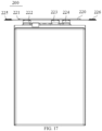
- FIG. 17 a fifth schematic structural diagram of a battery provided in an embodiment of the present application.
- an embodiment of the present application provides a battery 200, including a battery cell 210.
- the battery cell 210 may be a battery cell with an aluminum housing, a soft-packaged battery cell, or a cylindrical battery cell.
- the battery cell may be a battery cell with an aluminum housing, and when the electronic device 100 is a laptop computer, the battery cell 210 may be a cylindrical battery cell.
- the embodiment of the present application does not limit the specific type of the battery cell 210, nor is it limited to the above examples.
- the battery cell 210 includes a battery cell body 211 and two tabs 212 connected to the battery cell body 211.
- the two tabs 212 can be both disposed at one end of the battery cell body 211 to facilitate connection of the two tabs 212.
- the polarities of the two tabs 212 are opposite.
- one of the tabs 212 is a positive tab 212 and the other one of the tabs 212 is a negative tab 212.
- the embodiment of the present application does not limit the specific polarities of the two tabs 212, nor is it limited to the above examples.
- the battery 200 also includes a protection board assembly 220, which can be connected to the tabs 212 and to the electronic element 120 of the electronic device 100, to achieve adaption for the battery cell 210.
- the protection board assembly 220 can protect the battery cell 210, for example, when an external power supply charges the battery 200 and the interior of battery 200 reaches a protection state, the internal circuit of the protection board assembly 220 will be automatically cut off to avoid overcharging; for example, when the battery 200 is over-discharged, the discharge circuit of the protection board assembly 220 will be automatically cut off to ensure that the battery 200 is not completely discharged; definitely, the stability of the current inside the battery 200 can also be ensured to avoid overheating of the battery 200 during discharge; in addition, the protection board assembly 220 can isolate multiple batteries 200 to avoid short circuit.
- the battery 200 may also include a connecting member 230, the connecting member 230 includes connecting tabs 231 and a connecting portion 232, the number of the connecting tabs 231 is two.
- the connecting portion 232 is connected to the two connecting tabs 231, one of the connecting tabs 231 is connected to and is electrically conducted with one of the tabs 212, to form a composite tab 240. That is, the composite tab 240 is electrically conducted with the battery cell body 211.
- the composite tab 240 and the other one of the tabs 212 are both connected to the protection board assembly 220 to form a first loop.
- the other one of the connecting tabs 231 and the other one of the tabs 212 are both connected to the protection board assembly 220 to form a second loop, and the first loop and the second loop can form two parallel current loops, that is, the protection board assembly 220 and the battery cell 210 have two parallel loops formed, hence the magnitude of the current in a single loop of the protection board assembly 220 can be reduced, and the size of the protection board assembly 220 can be decreased, and the accommodating size of the battery 200 can be increased, thereby increasing the capacity of the battery cell 210, that is, increasing the capacity of the battery 200.
- the number of connecting members 230 can also be multiple.
- the number of connecting members 230 is two, there are two pairs of connecting tabs 231 accordingly, one of the connecting tabs 231 in each pair is connected to one of the tabs 212 to form a composite tab 240, the composite tab 240 is connected to the other one of the tabs 212 to form a current loop, and the other one of the connecting tabs 231 in each pair is respectively connected to the other one of the tabs 212 to form two parallel current loops, thereby forming three parallel current loops.
- the number of connecting members 230 is three
- the embodiment of the present application does not limit the number of the connecting members 230, nor is it limited to the above examples.
- the connecting portion 232 includes a connecting portion body 2321 and a boss 2322.
- connecting portion body 2321 and the boss 2322 can be formed as an integral structure to enhance the structural stability of the connecting portion 232 and facilitate processing.
- the connecting portion body 2321 and the boss 2322 can also be connected by means of welding or bonding.
- the material for preparing the connecting portion body 2321 and the boss 2322 can be selected from metals with conductive function, and the material for preparing the tab 212 can also be selected from metals with conductive function. That is, the material for preparing the connecting member 230 can be selected from metals with conductive function, such as copper, nickel, etc.
- the embodiment of the present application does not limit the material for preparing the above structure, nor is it limited to the above examples.
- the connecting portion body 2321 can be connected with the two connecting tabs 231, and the two connecting tabs 231 can be respectively located on opposite sides of the connecting portion body 2321, or respectively located on adjacent sides of the connecting portion body 2321, or located on the same side of the connecting portion body 2321.
- the embodiment of the present application does not limit the positional relationship between the connecting tabs 231 and the connecting portion body 2321, nor is it limited to the above examples.
- the boss 2322 is connected to the battery cell body 211 to achieve electrical conduction between the connecting member 230 and the battery cell body 211. It can be understood that the boss 2322 can be bent, and the battery cell body 211 has a groove (not shown in the figures) corresponding to the boss 2322. The boss 2322 is located in the groove and is in contact with an inner wall and/or a bottom wall of the groove to achieve connection between the boss 2322 and the battery cell body 211, thereby achieving the electrical conduction between the connecting member 230 and the battery cell body 211.
- the boss 2322 is located at a position on the connecting portion body 2321 corresponding to any one of the two connecting tabs 231, and is located on a side of the connecting portion body 2321 close to the battery cell body 211.
- the two connecting tabs 231 can be located on a side of the connecting portion body 2321 away from the battery cell body 211, and the boss 2322 is located on a side of the connecting portion body 2321 close to the battery cell body 211. That is, the boss 2322 and the two connecting tabs 231 are respectively located on opposite sides of the connecting portion body 2321, and the boss 2322 corresponds to any one of the connecting tabs 231.
- the extending direction of the boss 2322 and the extending direction of the corresponding connecting tab 231 can be in the same straight line, and intersects with the extending direction of the connecting portion body 2321.
- the connecting tab 231 corresponding to the boss 2322 can be connected to and is electrically conducted with one of the tabs 212 to form a composite tab 240.
- the composite tab 240 is connected to the battery cell body 211 through the boss 2322 nearby, and is connected to the other one of the tabs 212 and the protection board assembly 220 to form a first loop, and the current flow efficiency is relatively high; the connecting tab 231 that does not correspond to the boss 2322 is connected to the other one of the tabs 212 and the protection board assembly 220 to form a second loop.
- the first loop and the second loop can form two parallel current loops, that is, the protection board assembly 220 and the battery cell 210 have two parallel loops formed, hence the magnitude of the current in a single loop of the protection board assembly 220 can be reduced, and the size of the protection board assembly 220 can be decreased, and the accommodating size of the battery 200 can be increased, thereby increasing the capacity of the battery cell 210, that is, increasing the capacity of the battery 200.
- the boss 2322 is located on the connecting portion body 2321 between the two connecting tabs 231. Specifically, the boss 2322 is located on the corresponding connecting portion body 2321 between the two tabs 212, that is, the boss 2322 does not correspond to any connecting tab 231. At this time, any one of the connecting tabs 231 can be connected to and electrically conducted with one of the tabs 212 to form a composite tab 240.
- the composite tab 240 is connected to the battery cell body 211 through the boss 2322 located at the connecting portion body 2321, and connected to the other one of the tabs 212 and the protection board assembly 220 to form a first loop, and the other one of the connecting tabs 231 is connected to the other one of the tabs 212 and the protection board assembly 220 to form a second loop.
- the first loop and the second loop can form two parallel current loops, that is, the protection board assembly 220 and the battery cell 210 have two parallel loops formed, hence the magnitude of the current in a single loop of the protection board assembly 220 can be reduced, and the size of the protection board assembly 220 can be decreased, and the accommodating size of the battery 200 can be increased, thereby increasing the capacity of the battery cell 210, that is, increasing the capacity of the battery 200.
- the boss 2322 is located on the side of the connecting portion body 2321 close to the battery cell body 211, that is, the two connecting tabs 231 can be located on the side of the connecting portion body 2321 away from the battery cell body 211, and the boss 2322 is located on the side of the connecting portion body 2321 close to the battery cell body 211, that is, the boss 2322 and the two connecting tabs 231 are respectively located on the opposite sides of the connecting portion body 2321.
- the boss 2322 is close to the battery cell body 211, and correspondingly, the depth of the groove of the battery cell body 211 corresponding to the boss 2322 is larger, the length required for the boss 2322 to bend into the groove is larger, and the contact area between the boss 2322 and the groove is larger, that is, the connection between the boss 2322 and the battery cell body 211 is more stable, which is convenient for current conduction.
- the boss 2322 is located on the side of the connecting portion body 2321 away from the battery cell body 211, that is, the two connecting tabs 231 can be located on the side of the connecting portion body 2321 away from the battery cell body 211, and the boss 2322 is located on the side of the connecting portion body 2321 away from the battery cell body 211, that is, the boss 2322 and the two connecting tabs 231 are both located on the side of the connecting portion body 2321 away from the battery cell body 211, and the boss 2322 is located between the two connecting tabs 231, and the boss 2322 is away from the battery cell body 211.
- the depth of the groove of the battery cell body 211 corresponding to the boss 2322 is smaller, and the length required for the boss 2322 to bend into the groove is smaller, which facilitates the connection between the boss 2322 and the battery cell body 211, that is, the connection between the connecting member 230 and the battery cell body 211.
- one of the connecting tabs 231 is stacked and connected with one of the tabs 212 to form a composite tab 240, which can reduce the space occupied by the connecting tab 231 and increase the contact area between the connecting tab 231 and the tab 212, thereby improving the structural stability of the composite tab 240.
- the protection board assembly 220 includes a circuit board 221, a first conductive member 222, a second conductive member 223 and a third conductive member 224, the first conductive member 222 is connected to the composite tab 240, the second conductive member 223 is connected to the other one of the tabs 212, and the third conductive member 224 is connected to the other one of the connecting tabs 231.
- the circuit board 221, the first conductive member 222, the second conductive member 223, the composite tab 240 and the other one of the tabs 212 form a first loop.
- the circuit board 221, the second conductive member 223, the third conductive member 224, the other one of the tabs 212 and the other one of the connecting tabs 231 form a second loop.
- the first loop and the second loop can form two parallel current loops, that is, the protection board assembly 220 and the battery cell 210 have two parallel loops formed, hence the magnitude of the current in a single loop of the protection board assembly 220 can be reduced, the size of the protection board assembly 220 can be decreased, and the accommodating size of the battery 200 can be increased, thereby increasing the capacity of the battery cell 210, that is, increasing the capacity of the battery 200.
- first conductive member 222, the second conductive member 223 and the third conductive member 224 are all electrically connected to the circuit board 221.
- first conductive member 222, the second conductive member 223 and the third conductive member 224 are all fixed to the circuit board 221 by welding, to achieve the conduction of the circuit.
- the materials used for preparing the first conductive member 222, the second conductive member 223 and the third conductive member 224 may be the same or different, but they are all conductive materials, such as copper, nickel and other metals.
- the embodiments of the present application do not limit the materials used for preparing the first conductive member 222, the second conductive member 223 and the third conductive member 224, nor are they limited to the above examples.
- the circuit board 221 may have a first external connecting member 225 and a second external connecting member 226 connected to the first loop and the second loop respectively, to electrically conduct the current in the battery cell body 211 to other electronic elements 120 through the first external connecting member 225 and the second external connecting member 226.
- the battery 200 also includes an insulating layer 250.
- the insulating layer 250 covers both sides of the connecting portion 232. Along the extending direction of the connecting portion 232, the edge of the insulating layer 250 protrudes beyond the edge of the connecting portion 232.
- the insulating layer 250 may only cover the surfaces on the two opposite sides of the connecting portion body 2321 to prevent the connecting portion body 2321 from being directly connected to the tabs 212 or the battery cell body 211 or other electronic elements 120 to cause a short circuit.
- the edge of the insulating layer 250 protrudes beyond the edge of the connecting portion 232 by a size of 0.2 mm to 1.0 mm.
- the edge of the insulating layer 250 protrudes beyond the edge of the connecting portion body 2321 to reduce the possibility of short circuit caused by direct connection between the connecting portion body 2321 and the tabs 212 or the battery cell body 211 or other electronic elements 120.
- the edge of the insulating layer 250 protrudes beyond the edge of the connecting portion body 2321 by a size ranging from 0.2 mm to 1.0 mm.
- the extending direction of the connecting tab 231 and the extending direction of the connecting portion body 2321 intersect with each other, and a first notch 233 is provided at the corner of the connection position between the connecting tab 231 and the connecting portion body 2321, and/or, referring to FIG. 3 and FIG.
- At least one tab 212 is located between two connecting tabs 231, and the orthographic projection of the tab 212 on the plane where the connecting portion body 2321 is located overlaps with at least part of the connecting portion body 2321, and a second notch 234 is provided on the connecting portion body 2321 located in an overlapping area, and/or a third notch 235 is provided at at least one corner of the connection position between the boss 2322 and the connecting portion body 2321.
- the connecting member 230 may have only the first notch 233 to prevent the connecting member 230 from tearing, or may have only the second notch 234 to provide bending space for the tab 212, or may have only the third notch 235 to facilitate the bending of the boss 2322, or may have both the first notch 233 and the second notch 234, or may have both the first notch 233 and the third notch 235, or may have all of the first notch 233, the second notch 234 and the third notch 235.
- the first notch 233 is located at the corner of the connection position between the connecting tab 231 and the connecting portion body 2321, that is, the number of first notches 233 is the same as the number of connecting tabs 231.
- the number of the connecting tabs 231 is two, there are two first notches 233; further, the first notch 233 can also be provided at the corner of the connection position between the boss 2322 and the connecting portion body 2321. That is, when a connecting member 230 has two connecting tabs 231, the corners of the connection positions between the two connecting tabs 231 and the connecting portion body 2321, and the corner of the connection position between the boss 2322 and the connecting portion body 2321 are all provided with a first notch 233 to prevent the connecting member 230 from tearing.
- first notch 233 can be square, circular, semicircular, etc.
- the embodiment of the present application does not limit the shape of the first notch 233 and nor is it limited to the above examples.
- the shapes of the second notch 234 and the third notch 235 may be the same as or different from the first notch 233, which will not be described in detail below.
- a second notch 234 can be provided at a position of the connecting portion 232 corresponding to the tab 212. Furthermore, the second notch 234 can be provided at a position of the connecting portion body 2321 corresponding to the tab 212.
- the second notch 234 can be provided at a position of the connecting portion 232 corresponding to the tab 212 to avoid contact between the bent tabs 212 and the connecting portion 232, thereby providing a bending space for the tab 212.
- the connecting member 230 can be located on the side where the bending direction of the tab 212 is located, or on the side away from the bending direction of the tab 212, that is, when the connecting member 230 is located on the side where the bending direction of the tab 212 is located, the connecting member 230 is located between the bent tabs 212. At this time, the connecting member 230 can be provided with a second notch 234 for the tab 212 to bend.
- a third notch 235 is provided at the corner of the connection position between the boss 2322 and the connecting portion body 2321.
- the insulating layer 250 may cover the connecting portion body 2321 and the first notch 233 and/or the second notch 234 and/or the third notch 235.
- the connecting member 230 is a flexible connecting member, and a portion of the connecting member 230 is bent and connected to the battery cell body 211.
- the connecting member 230 is made of a flexible material to facilitate bending.
- the bent portion may be a boss 2322, and the boss 2322 is bent and connected to the battery cell body 211 to fix the connecting member 230.
- a portion of the connecting member 230 is bent and enters a deep pit surface (not shown in the figure) of a top sealing of the battery cell body 211; or, a portion of the connecting member 230 is bent and enters a shallow pit surface of a top sealing of the battery cell body 211.
- a packaging process is usually required, and a deep pit surface and a shallow pit surface are formed on a top sealing of the battery cell body 211.
- a portion of the connecting member 230 is the boss 2322, that is, the boss 2322 can be bent into the deep pit surface of the top sealing, or into the shallow pit surface of the top sealing, for connection to the battery cell body 211, thereby fixing the connecting member 230 and improving the connection stability between the connecting member 230 and the battery cell 210.
- the connecting member 230 is fixedly connected to the top sealing of the battery cell body 211 by means of double-sided tape or adhesive tape or glue. That is, the boss 2322 is fixedly connected to the top sealing of the battery cell body 211 by double-sided tape, or by adhesive tape, or by glue, for connection to the battery cell body 211, thereby fixing the connecting member 230 and improving the connection stability between the connecting member 230 and the battery cell 210.
- the connecting portion 232 is bonded to the battery cell 210 by a fixing glue.
- the fixing glue can be located on a surface on the side of the connecting portion body 2321 close to the battery cell 210 and located at the end of the battery cell body 211 close to the side where the tab 212 is located, to fix the connecting member 230.
- the fixing glue is one of double-sided tape, adhesive tape and glue.
- the fixing glue can be an insulating glue, that is, while fixing the connecting member 230, it prevents the connecting portion body 2321 from being directly connected to the tab 212 or the battery cell body 211 or other electronic elements 120 to cause a short circuit.
- orientations or positional relationships indicated by terms such as “upper”, “lower”, “front”, “back”, “vertical”, “horizontal”, “top”, “bottom”, “inside” and “outside” are based on the orientations or positional relationships shown in the accompanying drawings and are only for the convenience of describing the present application and simplifying the description. They do not indicate or imply that the device or element referred to must have a specific orientation, be constructed and operated in a specific orientation, and therefore should not be interpreted as a limitation on the present application. In the description of the present application, "a plurality of” means two or more than two, unless otherwise precisely and specifically specified.
Landscapes
- Chemical & Material Sciences (AREA)
- Chemical Kinetics & Catalysis (AREA)
- Electrochemistry (AREA)
- General Chemical & Material Sciences (AREA)
- Engineering & Computer Science (AREA)
- Manufacturing & Machinery (AREA)
- Microelectronics & Electronic Packaging (AREA)
- Connection Of Batteries Or Terminals (AREA)
Applications Claiming Priority (2)
| Application Number | Priority Date | Filing Date | Title |
|---|---|---|---|
| CN202222954173.XU CN218513631U (zh) | 2022-11-07 | 2022-11-07 | 电池及电子设备 |
| PCT/CN2023/117227 WO2024098927A1 (fr) | 2022-11-07 | 2023-09-06 | Batterie et dispositif électronique |
Publications (3)
| Publication Number | Publication Date |
|---|---|
| EP4507108A1 true EP4507108A1 (fr) | 2025-02-12 |
| EP4507108A4 EP4507108A4 (fr) | 2025-10-22 |
| EP4507108B1 EP4507108B1 (fr) | 2026-04-29 |
Family
ID=85219552
Family Applications (1)
| Application Number | Title | Priority Date | Filing Date |
|---|---|---|---|
| EP23887621.3A Active EP4507108B1 (fr) | 2022-11-07 | 2023-09-06 | Batterie et dispositif électronique |
Country Status (4)
| Country | Link |
|---|---|
| US (1) | US20250046966A1 (fr) |
| EP (1) | EP4507108B1 (fr) |
| CN (1) | CN218513631U (fr) |
| WO (1) | WO2024098927A1 (fr) |
Families Citing this family (2)
| Publication number | Priority date | Publication date | Assignee | Title |
|---|---|---|---|---|
| CN218513631U (zh) * | 2022-11-07 | 2023-02-21 | 珠海冠宇电源有限公司 | 电池及电子设备 |
| CN116759761A (zh) * | 2023-07-03 | 2023-09-15 | 珠海冠宇电源有限公司 | 一种电池和电子设备 |
Family Cites Families (6)
| Publication number | Priority date | Publication date | Assignee | Title |
|---|---|---|---|---|
| CN110112479B (zh) * | 2019-04-25 | 2021-11-19 | 浙江锋锂新能源科技有限公司 | 一种高容量保持率锂离子电池的充放电方式 |
| CN115275365B (zh) * | 2019-09-25 | 2025-08-19 | 荣耀终端股份有限公司 | 支持高功率快充的电池模组、充电模组和电子设备 |
| CN111403675A (zh) * | 2020-04-20 | 2020-07-10 | 东莞新能德科技有限公司 | 电池和电子装置 |
| CN112133876B (zh) * | 2020-08-31 | 2023-03-31 | 东莞新能德科技有限公司 | 电池及终端设备 |
| CN113851793A (zh) * | 2021-10-21 | 2021-12-28 | 广东国光电子有限公司 | 一种多极耳电芯、电池及电池制作方法 |
| CN218513631U (zh) * | 2022-11-07 | 2023-02-21 | 珠海冠宇电源有限公司 | 电池及电子设备 |
-
2022
- 2022-11-07 CN CN202222954173.XU patent/CN218513631U/zh active Active
-
2023
- 2023-09-06 EP EP23887621.3A patent/EP4507108B1/fr active Active
- 2023-09-06 WO PCT/CN2023/117227 patent/WO2024098927A1/fr not_active Ceased
-
2024
- 2024-10-21 US US18/922,135 patent/US20250046966A1/en active Pending
Also Published As
| Publication number | Publication date |
|---|---|
| EP4507108A4 (fr) | 2025-10-22 |
| EP4507108B1 (fr) | 2026-04-29 |
| CN218513631U (zh) | 2023-02-21 |
| WO2024098927A1 (fr) | 2024-05-16 |
| US20250046966A1 (en) | 2025-02-06 |
Similar Documents
| Publication | Publication Date | Title |
|---|---|---|
| US20250046966A1 (en) | Battery and electronic device | |
| CN104377339B (zh) | 可再充电电池组 | |
| KR100824876B1 (ko) | 배터리 팩 | |
| WO2020259322A1 (fr) | Dispositif électronique | |
| EP2760064B1 (fr) | Bloc-batteries | |
| CN104247094A (zh) | 不规则结构的电池单元和采用该电池单元的电池模块 | |
| CN212011033U (zh) | 电池及具有所述电池的电子装置 | |
| EP4064505A1 (fr) | Dispositif terminal | |
| CN112133876A (zh) | 电池及终端设备 | |
| EP4258431A1 (fr) | Élément de collecte de courant, cellule et dispositif électronique | |
| US20250266488A1 (en) | Battery and electronic apparatus | |
| EP4064401A2 (fr) | Cellule de batterie et appareil électrique | |
| CN214378578U (zh) | 电池组件及电子设备 | |
| EP4095990A1 (fr) | Élément de batterie, bloc-batterie et dispositif électronique | |
| CN114361559A (zh) | 电池 | |
| EP3671942A1 (fr) | Boîtier de terminal ayant une fonction d'estimation d'état de batterie secondaire améliorée | |
| US20250087790A1 (en) | Electrochemical device and electrical device | |
| CN116231237A (zh) | 电池及用电设备 | |
| CN217823177U (zh) | 电池及电子设备 | |
| CN218385307U (zh) | 电池 | |
| CN117996369A (zh) | 二次电池以及电子装置 | |
| US20260066507A1 (en) | Battery | |
| CN119726002B (zh) | 电化学装置以及用电设备 | |
| CN219959180U (zh) | 一种电池和电子设备 | |
| EP4715953A1 (fr) | Ensemble batterie et dispositif d'entraînement de batterie |
Legal Events
| Date | Code | Title | Description |
|---|---|---|---|
| STAA | Information on the status of an ep patent application or granted ep patent |
Free format text: STATUS: THE INTERNATIONAL PUBLICATION HAS BEEN MADE |
|
| PUAI | Public reference made under article 153(3) epc to a published international application that has entered the european phase |
Free format text: ORIGINAL CODE: 0009012 |
|
| STAA | Information on the status of an ep patent application or granted ep patent |
Free format text: STATUS: REQUEST FOR EXAMINATION WAS MADE |
|
| 17P | Request for examination filed |
Effective date: 20241107 |
|
| AK | Designated contracting states |
Kind code of ref document: A1 Designated state(s): AL AT BE BG CH CY CZ DE DK EE ES FI FR GB GR HR HU IE IS IT LI LT LU LV MC ME MK MT NL NO PL PT RO RS SE SI SK SM TR |
|
| A4 | Supplementary search report drawn up and despatched |
Effective date: 20250918 |
|
| RIC1 | Information provided on ipc code assigned before grant |
Ipc: H01M 50/50 20210101AFI20250912BHEP Ipc: H01M 50/519 20210101ALI20250912BHEP Ipc: H01M 50/572 20210101ALI20250912BHEP Ipc: H01M 10/42 20060101ALI20250912BHEP Ipc: H01M 50/557 20210101ALI20250912BHEP Ipc: H01M 50/574 20210101ALI20250912BHEP |
|
| DAV | Request for validation of the european patent (deleted) | ||
| DAX | Request for extension of the european patent (deleted) | ||
| GRAP | Despatch of communication of intention to grant a patent |
Free format text: ORIGINAL CODE: EPIDOSNIGR1 |
|
| STAA | Information on the status of an ep patent application or granted ep patent |
Free format text: STATUS: GRANT OF PATENT IS INTENDED |
|
| RIC1 | Information provided on ipc code assigned before grant |
Ipc: H01M 50/50 20210101AFI20260128BHEP Ipc: H01M 50/519 20210101ALI20260128BHEP Ipc: H01M 50/572 20210101ALI20260128BHEP Ipc: H01M 10/42 20060101ALI20260128BHEP Ipc: H01M 50/557 20210101ALI20260128BHEP Ipc: H01M 50/574 20210101ALI20260128BHEP |
|
| GRAS | Grant fee paid |
Free format text: ORIGINAL CODE: EPIDOSNIGR3 |
|
| GRAA | (expected) grant |
Free format text: ORIGINAL CODE: 0009210 |
|
| STAA | Information on the status of an ep patent application or granted ep patent |
Free format text: STATUS: THE PATENT HAS BEEN GRANTED |
|
| INTG | Intention to grant announced |
Effective date: 20260226 |
|
| AK | Designated contracting states |
Kind code of ref document: B1 Designated state(s): AL AT BE BG CH CY CZ DE DK EE ES FI FR GB GR HR HU IE IS IT LI LT LU LV MC ME MK MT NL NO PL PT RO RS SE SI SK SM TR |
|
| REG | Reference to a national code |
Ref country code: CH Ref legal event code: F10 Free format text: ST27 STATUS EVENT CODE: U-0-0-F10-F00 (AS PROVIDED BY THE NATIONAL OFFICE) Effective date: 20260429 |