EP4508970A1 - Machine de travail agricole dotée d'un système d'aide à la conduite - Google Patents
Machine de travail agricole dotée d'un système d'aide à la conduite Download PDFInfo
- Publication number
- EP4508970A1 EP4508970A1 EP24182873.0A EP24182873A EP4508970A1 EP 4508970 A1 EP4508970 A1 EP 4508970A1 EP 24182873 A EP24182873 A EP 24182873A EP 4508970 A1 EP4508970 A1 EP 4508970A1
- Authority
- EP
- European Patent Office
- Prior art keywords
- working
- process model
- assistance system
- driver assistance
- parameters
- Prior art date
- Legal status (The legal status is an assumption and is not a legal conclusion. Google has not performed a legal analysis and makes no representation as to the accuracy of the status listed.)
- Pending
Links
Images

Classifications
-
- A—HUMAN NECESSITIES
- A01—AGRICULTURE; FORESTRY; ANIMAL HUSBANDRY; HUNTING; TRAPPING; FISHING
- A01D—HARVESTING; MOWING
- A01D41/00—Combines, i.e. harvesters or mowers combined with threshing devices
- A01D41/12—Details of combines
- A01D41/127—Control or measuring arrangements specially adapted for combines
-
- G—PHYSICS
- G05—CONTROLLING; REGULATING
- G05B—CONTROL OR REGULATING SYSTEMS IN GENERAL; FUNCTIONAL ELEMENTS OF SUCH SYSTEMS; MONITORING OR TESTING ARRANGEMENTS FOR SUCH SYSTEMS OR ELEMENTS
- G05B13/00—Adaptive control systems, i.e. systems automatically adjusting themselves to have a performance which is optimum according to some preassigned criterion
- G05B13/02—Adaptive control systems, i.e. systems automatically adjusting themselves to have a performance which is optimum according to some preassigned criterion electric
- G05B13/04—Adaptive control systems, i.e. systems automatically adjusting themselves to have a performance which is optimum according to some preassigned criterion electric involving the use of models or simulators
Definitions
- the invention relates to an agricultural working machine comprising a driver assistance system according to the preamble of claim 1.
- driver assistance systems that optimize the operation of agricultural machines, especially harvesting machines, and thereby largely relieve the operator of the agricultural machine of monitoring and adjustment tasks have already been comprehensively described in the state of the art.
- DE 10 2010 017 687 A1 A driver assistance system has become known which determines optimized setting parameters for the working elements of an agricultural harvesting machine based on a characteristic map.
- the method disclosed here approaches optimized working parameters in an iterative process.
- Such systems are well suited to quickly determining optimized working parameters of the harvesting machine under more or less homogeneous harvesting conditions. Under rapidly changing harvesting conditions, such methods have the disadvantage that, due to the inertia of the optimization method, a certain transient process must be run through until the harvesting machine is again working at an optimized operating point.
- the agricultural work machine comprising a driver assistance system which is intended and set up to automatically monitor and adjust working parameters and quality parameters of the agricultural work machine, wherein the driver assistance system is assigned a process model comprising characteristic fields, so that the optimization method implemented by the driver assistance system is designed as a characteristic field control and the optimization method generates optimized working parameters as a manipulated variable and the driver assistance system determines the quality parameters of the agricultural work machine depending on the optimized working parameters and the process model is designed as a dynamic non-linear process model in such a way that the dynamic non-linear process model comprises a static process model part and a dynamic process model part, wherein at least the manipulated variables in the static process model part go through an optimization step and in the dynamic process model part go through a control loop structure, it is ensured that the driver assistance system can quickly adapt the optimization of the working parameters to changing process conditions, abruptly changing harvesting conditions.
- the characteristic map control defined by the process model is set up and designed to specify the working parameters of the agricultural working machine and limit values for the control loop structure, wherein a self-adjusting controller is assigned to the control loop structure and the self-adjusting controller is designed and configured to monitor the quality parameters of the process. This has the particular effect that the operation of the agricultural machine is always operated at an optimal operating point.
- the optimization step and the control loop structure form an optimization method which is intended and set up to operate the process model in a model adaptation step in such a way that the dynamic non-linear process model component is intended and set up to determine the stationary model component of the process from the monitoring of the quality parameters and using a parameter estimation method, wherein the one or more manipulated variables comprising the optimized working parameters and the one or more quality parameters dependent on the respective manipulated variable form input variables of the optimization method.
- This has the effect in particular that the process optimization is limited to the essential parameters, so that the required computing power can be limited to a level which enables the optimization method to be used in an ongoing harvesting operation.
- an advantageous embodiment of the invention initially ensures that the working parameters describing the real process are sufficiently taken into account in the entire optimization process.
- control loop structure comprising the self-adjusting controller as input variables the manipulated variables optimized in the optimization step, the specified quality parameters and the quality parameters determined as a function of the optimized manipulated variables and by further providing and setting up the self-adjusting controller to derive optimized manipulated variables from a comparison of the specified quality parameters with the determined quality parameters and to pass them on to the process and the model adaptation step of the dynamic model adaptation, several effects are achieved.
- the optimized parameters determined by the control loop structure also correspond to the stored process model. so that it is gradually adapted so that it describes the changed conditions of the process with sufficient accuracy.
- the determined quality parameter is also passed on to the model adaptation step as an input variable so that the changed process conditions can be taken into account with sufficient accuracy in the model adaptation.
- the driver assistance system can optimize the operation of the agricultural machine sufficiently quickly if the driver assistance system is set up in an advantageous further development to automatically adjust the optimized control variables to the working elements of the agricultural machine.
- control loop structure is provided and configured to effect a dynamic adaptation of the process before the stored process model has been adjusted to the process.
- a particularly efficient optimization of the operation of the agricultural working machine results in a further advantageous embodiment when the nonlinear dynamic process model describes the relationship between the working parameters of a working organ and the quality parameters.
- a mathematically simple check of the quality parameter describing the current mode of operation of the agricultural work machine is achieved in that the limit values assigned to the quality parameters are structured in such a way that it is determined in a test step whether the quality parameter achieved is still within the limit value defined for the quality parameter or not, whereby the control loop structure is activated if the limit value is exceeded and the activation of the control loop structure is then omitted or terminated if the limit value is not or is no longer exceeded.
- control loop structure remains activated until the optimized working parameters derived from the non-linear dynamic model meet the quality criteria of the process. In this way This ensures that the operation of the agricultural machine is maintained in accordance with the selected harvesting process strategy even while the process model is being adjusted to the real process conditions.
- a particularly efficient process model-based control of the operation of an agricultural work machine is achieved in an advantageous development of the invention when the working elements of the agricultural work machine are combined to form process unit machines and one or more working elements together with the driver assistance system form a process unit machine, wherein process models describing the respective process unit machine are stored in a storage unit assigned to the driver assistance system and the computing unit is provided and set up to operate the process unit machine using the stored process models and the process unit machine is set up to optimize working parameters of the working element(s) and to specify the optimized working parameters for the respective working element.
- the agricultural work machine is designed as a combine harvester and the process unit machine is designed at least as a threshing machine and/or as a separating machine and/or as a cleaning machine and a process model is assigned to each of these process unit machines.
- a further advantageous embodiment provides that at least the threshing machine and the separating machine are assigned a common process model, preferably the threshing machine and the separating machine and the cleaning machine are assigned a common process model. This has the effect, above all, that the required computing power decreases significantly with a reduction in the number of map-based models to be used.
- the dynamic non-linear process model preferably the dynamic process model part
- the parameter estimation method is preferably formed by a so-called LMN-FIR model (Local Model Networks with local Finite Impulse Response Models).
- LMN-FIR model Local Model Networks with local Finite Impulse Response Models
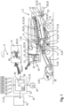
- the in Fig. 1 The agricultural work machine 1, which is shown schematically and is designed as a combine harvester 2, has a grain cutting device 3 in its front area, which is connected in a manner known per se to the inclined conveyor 4 of the combine harvester 2.
- the crop flow 5 running through the inclined conveyor 4 is transferred in the upper, rear area of the inclined conveyor 4 to the threshing elements 7 of the combine harvester 2, which are at least partially enclosed at the bottom by a so-called threshing concave 6.
- a deflection drum 8 arranged downstream of the threshing elements 7 deflects the crop flow 5 emerging from the threshing elements 7 in the rear area of the threshing elements 7 in such a way that it is transferred directly to a separating device 10 designed as a separating rotor arrangement 9.
- the separating device 10 can also be designed as a tray shaker, which is known per se and therefore not shown. It is also within the scope of the invention that the separating device can be designed with one or two rotors or that the threshing elements 7 and the separating device 10 are combined to form a single or two rotor axial flow threshing and separating device. In the separating device 10, the crop stream 5 is conveyed in such a way that freely moving grains 11 contained in the crop stream 5 are separated in the lower area of the separating device 10.
- Both the grains 11 separated on the threshing concave 6 and in the separating device 10 are fed via the return floor 12 and feed floor 13 to a cleaning device 17 consisting of several sieve levels 14, 15 and a blower 16.
- the cleaned grain stream 18 is finally transferred to a grain tank 20 by means of elevators 19.
- a shredding device 23 which is encased in a funnel-shaped housing 21 and designed as a straw chopper 22, is assigned to it.
- the straw leaving the separating device 10 in the rear area is 24.
- the straw 24 can also be diverted after the separating device 10 so that it is deposited directly on the ground 25 in a swath.
- the material flow consisting of the shredded straw 24 and the non-grain components separated in the cleaning device 17 are transferred to a material distribution device 26, which releases the residual material flow 27 in such a way that the residual material flow 27 is widely distributed on the ground 25.
- the residual material flow 28 separated in the cleaning device 17 is released into the straw chopper 22 by means of a so-called chaff distributor 29 and is ultimately conveyed out of the combine harvester 12 as a common residual material flow 27 by means of the material distribution device 26.
- the grain cutting device 3, the inclined conveyor 4, the threshing elements 7 and the threshing concave 6 associated with them, the separating device 10, the cleaning device 17, the elevators 18, the grain tank 20, the straw chopper 22, the material distribution device 26 and the chaff distributor 29 are referred to as working elements 30 of the agricultural working machine 1.
- the agricultural working machine 1 has a vehicle cabin 31 in which at least one control and regulating device 33 provided with a display unit 32 is arranged, by means of which a large number of processes P to be described in more detail can be controlled automatically or initiated by the operator 34 of the agricultural working machine 1.
- the control and regulating device 33 communicates via a so-called bus system 35 in a manner known per se with a large number of sensor systems 36. Details regarding the structure of the sensor systems 36 are described in detail in the DE 101 47 733 described, the content of which hereby becomes a full part of the disclosure of this patent application, so that the structure of the sensor systems 26 is not described again below.
- Fig. 1 a schematic representation of the display unit 32 of the control and regulating device 33 and the computing unit 37 assigned to the control and regulating device 33 and coupled to the display unit 32.
- the computing unit 37 is designed in such a way that, in addition to the information 38 generated by the sensor systems 36, it can process external information 39 and information 40 stored in the computing unit 37 itself, such as expert knowledge, to produce a large number of output signals 41.
- the output signals 41 are designed in such a way that they comprise at least display control signals 42 and work element control signals 43, the former determining the contents of the display unit 32 and the latter determining the change in the most varied working parameters 44 of the Working elements 30 of the agricultural working machine 1, whereby arrow 44 symbolically represents the threshing drum speed.
- the control and regulating device 33 with the associated display unit 32 and the computing unit 37 are part of the driver assistance system 45 according to the invention, which will be described in more detail below.
- a process optimization module 46 is assigned to the driver assistance system 45, wherein the process optimization module 46 is preferably part of the computing unit 37.
- One or more process models 47 are assigned to the process optimization module 46, which describe the processes P running in the agricultural work machine 1, which are to be described in more detail below.
- the single or multiple process models 47 are described by characteristic curve fields 48, wherein the relationship between quality parameters 49 and working parameters 50a..i of the agricultural work machine 1 is defined in each characteristic curve field 48.
- the processes P described by the respective process model 47 can be, for example, the threshing process, the separation process or the cleaning process of the crop 5, to name just a few processes P as examples.
- the quality parameters can be, for example, the quality parameters "threshing loss”, “broken grain content”, “separation loss”, “cleaning loss”, “threshing gear load” and “fuel consumption”, which are known per se and therefore not described in more detail here.
- the working parameters 50a..i of the agricultural working machine include, on the one hand, parameters related to the crop flow 5, such as the crop throughput, the layer height of the crop flow 5 detected in the agricultural working machine and/or the moisture of the crop flow 5.
- the working parameters 50a..i include parameters related to the working elements 30 of the agricultural working machine, such as the aforementioned threshing drum speed 44 and/or the speed of the fan 16 assigned to the cleaning device 17, to name just two examples here.
- the Figure 1 The example shown for a characteristic map 48 describing a process model 47 could, for example, describe the quality parameter 49 "separation loss" as a function of the working parameters threshing drum speed 44, 50a and the layer height 50i related to the crop flow 5.
- an agricultural working machine 1 designed as a combine harvester 2 comprising the described driver assistance system 45, which is provided and set up to automatically monitor and adjust the working parameters 44, 50a..i and the quality parameters 49 of the combine harvester 2, a Driver assistance system 45, which supports the operator 34 of the combine harvester 2 in operating the combine harvester 2.
- the driver assistance system 45 is assigned a process model 47 comprising characteristic fields 48 and the process model 47 defines the respective quality parameter 49 depending on manipulated variables 51, here the working parameters 50a..i, and the driver assistance system 50 is set up in a manner to be described in more detail to determine optimized working parameters 50a..i of the agricultural work machine 1 depending on the respective process model 47.
- the driver assistance system 45 optimizes the working parameters 44, 50a..i of the agricultural work machine 1 designed as a combine harvester 2 in an optimization step 52.
- the optimization of the working parameters 44, 55a..i depends on a preselected harvesting process strategy 53 that determines the optimization step 52, wherein the harvesting process strategy 53 is generally specified by the operator 34 and, in the simplest case, defines the quality parameters 49 to be achieved, such as maximum permissible grain losses or a purity of the grains 11 to be achieved, to name just two quality criteria 49 as examples.
- the optimized working parameters 44, 55a..i determined in the optimization step 52 are then transferred to the process P and automatically set on the respective working elements 30 of the combine harvester 2, such as an optimized speed 44 of a threshing drum assigned to the threshing elements 7.
- the driver assistance system 45 determines the quality criteria 49a resulting from an adjustment of the working parameters 44, 55a..i.
- Both the optimized working parameters 44, 50a..i and the determined quality parameters 49a are transmitted to the process optimization module 46 in a model adaptation step 54, whereby the process model 47 is adapted in a manner known per se depending on the transmitted parameters 44, 50a..i, 49a if the stored process model 47 no longer describes the actual process P sufficiently well.
- the model adaptation step 54 known from the prior art is designed as a so-called stationary model adaptation 55, in which quasi-stationary states are first determined for the manipulated variables 51 and the determined quality parameters 49a in a data preprocessing step 56. The values corresponding to the quasi-stationary state for the manipulated variables 51 and the determined quality parameters 49a are then transmitted to the process optimization module 46 for Adaptation of the process model 47 is passed on.
- This tracking of the process model 47 to the real process P is referred to below as sluggish model adaptation 55, since a certain settling time is always passed through until the stored process model 47 is adapted to the real process P. If conditions describing the process P, such as the crop throughput or the moisture of the crop stream 5, change abruptly and/or only briefly, this control structure has the disadvantage that it cannot react sufficiently well to the changing conditions of the process P, which ultimately leads to the quality criteria 49 specified by the selected harvesting process strategy 53 not being able to be met sufficiently well. This is where the invention comes in.
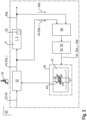
- Fig. 3 now shows details of the driver assistance system 45 according to the invention with the process optimization module 46 assigned to it, in which the process model 47 and the characteristic curve fields 48 assigned to the process model 47 are stored, wherein the process model 47 describes the relationship between working parameters 50a..i of a working element 30, the manipulated variables 51, and the quality parameters 49, so that the optimization method (65) to be implemented by the driver assistance system (45) and to be explained in more detail is designed as a characteristic field control (69).
- the process model 47 is assigned a model adaptation step 57 which, according to the invention and to be explained in more detail, is designed as a dynamic model adaptation 58, so that the stored process model 47 is designed according to the invention as a non-linear dynamic process model 59, wherein the non-linear dynamic process model 59 is composed of a static process model part 60 and a dynamic process model part 61.
- the non-linear dynamic process model 59 also represents the relationship between working parameters 50a..i of a working element 30, the manipulated variables 51, and the quality parameters 49.
- the characteristic map control 69 is set up and designed such that it specifies the working parameters 44, 50a..i of the agricultural working machine 1 and limit values 66 to be described in more detail for the control loop structure 62, wherein the control loop structure 62 is assigned a self-adjusting controller 63 and the self-adjusting controller 63 is provided and set up to monitor the quality parameters 49, 49a of the process.
- optimized manipulated variables 51', the working parameters 44, 50a..i, are first determined in an optimization step 52 from the quality criteria 49 assigned to the selected harvesting process strategy 53 and the manipulated variables 51 derived from the process model 47.
- the dynamic process model portion 61 comprises a control loop structure 62 comprising a self-adjusting controller 63.
- Input variables E of the self-adjusting controller 63 are initially the optimized manipulated variables 51', the optimized working parameters 44, 50a..i, and the quality parameters 49 defined in the selected harvesting process strategy 53.
- the quality parameters 49a achieved in the process P by applying the optimized working parameters 44, 50a..i form input variables E of the self-adjusting controller 63.
- the manipulated variables 51 determined in the model adaptation step 57 are transferred to the self-adjusting controller 63 as further input variables E.
- the defined quality parameters 49 are compared with the achieved quality parameters 49a.
- dynamically adjusted working parameters 64a..i are generated taking into account the respective stored process model 47 and are automatically set on the respective working elements 30 in the agricultural work machine 1 designed as a combine harvester 2 that describes the process P. At the same time, these dynamically adjusted working parameters 64a..i are also transferred to the model adaptation step 57.
- the process model 47 as a dynamic non-linear process model 59 in such a way that the dynamic non-linear process model 59 comprises a static process model portion 60 and a dynamic process model portion 61, wherein at least the manipulated variables 51 in the static process model portion 60 pass through an optimization step 52 and in the dynamic process model portion 61 a control loop structure 62, it is ensured that the driver assistance system 45 and here specifically the optimization of the working parameters 50a..i adapt quickly to the real harvesting conditions, the process P, and in particular react quickly to abrupt changes in the harvesting conditions.
- the optimization step 52 and the control loop structure 62 form an optimization method 65, which is intended and set up to adapt the process model 47, 59 in a model adaptation step 57 in such a way that the dynamic non-linear process model component 61 is provided and set up to determine the stationary process model component (60) from the monitoring of the quality parameters 49, 49a and using a parameter estimation method 70. of the process (P), wherein the one or more manipulated variables 51 and the one or more quality parameters 49a dependent on the respective manipulated variable 51 in the model adaptation step 57 form the input variables of the optimization method 65.
- the non-linear dynamic process model 59 preferably the dynamic process model portion 61, can be designed as a self-learning process model in a preferred embodiment and the parameter estimation method 70 can preferably be formed by a LMN-FIR model (Local Model Networks with local Finite Impulse Response Models).
- LMN-FIR model Local Model Networks with local Finite Impulse Response Models
- the described control loop structure 62 is designed in such a way that it causes a dynamic adaptation of the process P until the stored process model 47, 59 has been adjusted to the process P.
- the adjustment of the stored process model 47, 59 is achieved in this context by the dynamic working parameters 64a..i generated by the self-adjusting controller 63 and the determined quality parameters 49a being passed on as input variables E to the model adaptation step 57 which effects the dynamic model adaptation 58.
- the stored model 47 is gradually adapted to the conditions of the process P.
- control loop structure 62 only causes a dynamic adjustment of the process P when the achieved quality parameters 49a no longer correspond to the quality parameters 49 defined in the selected harvesting process strategy 53, it is further provided that limit values 66 are assigned to the quality parameters 49, 49a and in a test step 67 it is first determined whether the achieved quality parameter 49a is still within the limit value 66 for the quality parameter 49 or not. If the determined quality parameter 49a exceeds the defined limit values 66, the control loop structure 62 is activated, whereas the control loop structure 62 does not intervene in the process P if the limit value 66 is not exceeded. In this way it is also ensured that the control loop structure 62 remains activated until the optimized working parameters 50a..i derived from the nonlinear dynamic process model 59 meet the quality criteria 49 of the process P.
- the optimization method 65 is integrated into the driver assistance system 45 assigned to the agricultural working machine 1, wherein the respective process model 47, 59 is stored in one of the control and Control device 33 associated memory unit 68 of the driver assistance system 45, so that the computing unit 37 is provided and set up to operate the optimization process 65 by means of the stored process model 47, 58.
- the driver assistance system 45 is set up as described by means of suitable sensor systems 36 ( Fig.1 ) to determine and make available the working parameters 44, 50a..i and the associated control variables 51.
- the driver assistance system 45 implementing the optimization process 65 is thus designed such that the characteristic map control 69 derives the working parameters 44, 50a..i and the quality criteria 49, 49a from the static process model portion 60 of the process P describing the machine behavior as well as the user specifications, the predeterminable harvesting process strategies 53 and the technical limits of the agricultural working machine 1 by means of optimization.
- the control loop structure 62 according to the invention, to which the self-adjusting controller 63 is assigned, the operation of the agricultural working machine 1 designed as a combine harvester 2 is controlled by monitoring the quality parameters 49, 49a.
- control loop structure 62 enables the adaptation of the stored process model 47, 58, whereby the described non-linear dynamic model component 61 of the quality parameters 49, 49a is determined by applying a parameter estimation method 70 and the process model 47 of the stationary machine behavior is determined therefrom.
- the characteristic map control 69 thus takes on two tasks, namely the direct specification of the working parameters 44, 50a..i of the working elements 30 and the specification of the limit values 66 of the control loop structure 62, whereby the self-adjusting controller 63 assigned to the control loop structure 62 monitors the quality parameters 49, 49a, whereby the control loop structure 62 can be designed such that the self-adjusting controller is designed either as a so-called standard controller for maintaining a setpoint or as a limit load controller, which is activated when the limit value 66 is exceeded and deactivated again when the limit value 66 is undershot.
- the optimization method according to the invention is therefore designed in such a way that it implements an adaptive pre-control 71 of the process P and also enables dynamic monitoring and control of the quality parameters 49, 49a.
- a simple implementation of this method can be achieved by first determining the optimized working parameters 44, 50a..i using the derived static process model component 60 and the quality parameters 49 that can be specified by the operator 34 of the agricultural work machine 1.
- the optimized working parameters 44, 50a..i determined in this way are then transferred to the control loop structure 62 in order to determine optimized working parameters 64a..i on the basis of the transferred working parameters 44, 50a..i and the transferred quality parameters 49.
- the optimized working parameters 64a..i are then set on the working elements 30 of the agricultural work machine 1 and the resulting quality criteria 49a of the process P are determined.
- the determined quality parameters 49a are compared with the predefined quality parameters 49 in a test step 67 depending on a limit value 66, whereby the control loop structure 62 is activated if the limit value 66 is exceeded and the activation of the control loop structure 62 is then omitted or terminated if the limit value 66 is not or no longer exceeded. If the control loop structure 62 is activated, the working parameters 64a..i determined by the control loop structure 62 are specified to the respective working element 30.
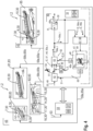
- FIG. 4 now describes the application of the described dynamic process model 59 in an agricultural working machine 1 designed as a combine harvester 2 in more detail.
- the driver assistance system 45 operates a so-called automatic-based control and regulation of the agricultural working machine 1.
- the threshing elements 7, the threshing concave 6 assigned to them and the deflection drum 8 are combined to form a so-called threshing machine 80.
- the separating device 10 is also known to design the separating device 10 as a so-called separating machine 81.
- cleaning machines 82 which are essentially made up of the working elements 30 of a cleaning device 17 and comprise at least the blower 16 and the sieve levels 14, 15.
- the process unit machines 83 mentioned here namely the threshing machine 680, the separating machine 781 and the cleaning machine 782, have the basic structure of an automatic machine in common, namely that the driver assistance system 45 with its associated control and regulating device 33 and the associated computing unit 37 and storage unit 68 are designed to autonomously determine individual working parameters 44, 50a..i of the respective working elements 30 and to specify them to the respective working element 30, whereby the basis for determining the respective working parameters 44, 50a..i is the described user-side selection of harvesting process strategies 53.
- the driver assistance system 45 is designed such that process models 47, 59 describing the respective process unit 83 are stored in the storage unit 68 of the driver assistance system 45 and the computing unit 37 is designed to use the stored process models 47, 59 to control the process unit 83 according to Figure 3 to operate, wherein the respective process unit automatic device 83 is set up to optimize working parameters 44, 50a..i of the working element(s) 30 and to specify the optimized working parameters 50a..i, 64a..i to the respective working element 30.
- the process model 47 is designed as a dynamic non-linear process model 59.
- the process unit automatic devices threshing machine 80, separating machine 81 and cleaning machine 82 are each assigned a separate dynamic process model 59a..c and associated optimization method 65a..c, so that the operation of each process unit automatic device 83 can be optimized independently of the operation of the other process unit automatic devices 83.
- the threshing machine 80 and the separating machine 81 can be combined to form a common separating machine 85, with the common separating machine 85 then being assigned a single dynamic process model 59d and associated optimization method 65d, which optimizes the operation of the threshing elements 7 and the associated working elements 30, threshing concave 6 and deflection drum 8, as well as the separating device 10.
- threshing machine (80) and the separating machine (81) and the cleaning machine (82) could be assigned a common process model (47) and associated optimization method (65).
Landscapes
- Environmental Sciences (AREA)
- Life Sciences & Earth Sciences (AREA)
- Engineering & Computer Science (AREA)
- Evolutionary Computation (AREA)
- Artificial Intelligence (AREA)
- Computer Vision & Pattern Recognition (AREA)
- Health & Medical Sciences (AREA)
- Medical Informatics (AREA)
- Software Systems (AREA)
- Physics & Mathematics (AREA)
- General Physics & Mathematics (AREA)
- Automation & Control Theory (AREA)
- Feedback Control In General (AREA)
- Harvester Elements (AREA)
Applications Claiming Priority (1)
| Application Number | Priority Date | Filing Date | Title |
|---|---|---|---|
| DE102023122014.4A DE102023122014A1 (de) | 2023-08-17 | 2023-08-17 | Landwirtschaftliche Arbeitsmaschine mit Fahrerassistenzsystem |
Publications (1)
| Publication Number | Publication Date |
|---|---|
| EP4508970A1 true EP4508970A1 (fr) | 2025-02-19 |
Family
ID=91585918
Family Applications (1)
| Application Number | Title | Priority Date | Filing Date |
|---|---|---|---|
| EP24182873.0A Pending EP4508970A1 (fr) | 2023-08-17 | 2024-06-18 | Machine de travail agricole dotée d'un système d'aide à la conduite |
Country Status (3)
| Country | Link |
|---|---|
| US (1) | US20250057079A1 (fr) |
| EP (1) | EP4508970A1 (fr) |
| DE (1) | DE102023122014A1 (fr) |
Families Citing this family (1)
| Publication number | Priority date | Publication date | Assignee | Title |
|---|---|---|---|---|
| DE102024123032A1 (de) | 2024-08-13 | 2026-02-19 | Claas Selbstfahrende Erntemaschinen Gmbh | Landwirtschaftliche Arbeitsmaschine mit Fahrerassistenzsystem |
Citations (6)
| Publication number | Priority date | Publication date | Assignee | Title |
|---|---|---|---|---|
| DE10147733A1 (de) | 2001-09-27 | 2003-04-10 | Claas Selbstfahr Erntemasch | Verfahren und Vorrichtung zur Ermittlung einer Erntemaschineneinstellung |
| US20050075737A1 (en) * | 1996-05-06 | 2005-04-07 | Martin Gregory D. | Method and apparatus for modeling dynamic and steady-state processes for prediction, control and optimization |
| DE102010017687A1 (de) | 2010-07-01 | 2012-01-05 | Claas Selbstfahrende Erntemaschinen Gmbh | Verfahren zur Einstellung zumindest eines Arbeitsorganes einer selbstfahrenden Erntemaschine |
| EP2687922A2 (fr) | 2012-07-16 | 2014-01-22 | CLAAS Selbstfahrende Erntemaschinen GmbH | Machine de travail agricole dotée d'au moins un dispositif de commande |
| EP1446997B2 (fr) * | 2003-02-17 | 2014-10-29 | CLAAS Selbstfahrende Erntemaschinen GmbH | Méthode pour l'optimisation de paramètres réglables |
| EP4154699A1 (fr) | 2021-09-28 | 2023-03-29 | CLAAS Selbstfahrende Erntemaschinen GmbH | Machine de travail agricole pourvu à commande de champ caractéristique |
-
2023
- 2023-08-17 DE DE102023122014.4A patent/DE102023122014A1/de active Pending
-
2024
- 2024-06-18 EP EP24182873.0A patent/EP4508970A1/fr active Pending
- 2024-08-19 US US18/808,214 patent/US20250057079A1/en active Pending
Patent Citations (6)
| Publication number | Priority date | Publication date | Assignee | Title |
|---|---|---|---|---|
| US20050075737A1 (en) * | 1996-05-06 | 2005-04-07 | Martin Gregory D. | Method and apparatus for modeling dynamic and steady-state processes for prediction, control and optimization |
| DE10147733A1 (de) | 2001-09-27 | 2003-04-10 | Claas Selbstfahr Erntemasch | Verfahren und Vorrichtung zur Ermittlung einer Erntemaschineneinstellung |
| EP1446997B2 (fr) * | 2003-02-17 | 2014-10-29 | CLAAS Selbstfahrende Erntemaschinen GmbH | Méthode pour l'optimisation de paramètres réglables |
| DE102010017687A1 (de) | 2010-07-01 | 2012-01-05 | Claas Selbstfahrende Erntemaschinen Gmbh | Verfahren zur Einstellung zumindest eines Arbeitsorganes einer selbstfahrenden Erntemaschine |
| EP2687922A2 (fr) | 2012-07-16 | 2014-01-22 | CLAAS Selbstfahrende Erntemaschinen GmbH | Machine de travail agricole dotée d'au moins un dispositif de commande |
| EP4154699A1 (fr) | 2021-09-28 | 2023-03-29 | CLAAS Selbstfahrende Erntemaschinen GmbH | Machine de travail agricole pourvu à commande de champ caractéristique |
Also Published As
| Publication number | Publication date |
|---|---|
| DE102023122014A1 (de) | 2025-02-20 |
| US20250057079A1 (en) | 2025-02-20 |
Similar Documents
| Publication | Publication Date | Title |
|---|---|---|
| EP1543712B1 (fr) | Procédé et dispositif pour régler les organes de travail d'une moissonneuse-batteuse | |
| EP2401904B2 (fr) | Système d'assistance du conducteur pour machine de travail agricole | |
| EP2401905B1 (fr) | Procédé de réglage d'au moins un organe de travail d'une moissonneuse automobile | |
| EP3566564B1 (fr) | Moissonneuse-batteuse et procédé de fonctionnement d'une moissonneuse-batteuse | |
| EP1277388B2 (fr) | Système de commande d'une machine agricole | |
| EP1731017B2 (fr) | Méthode de commande d'une moissoneuse | |
| EP1446997B1 (fr) | Méthode pour l'optimisation de paramètres réglables | |
| EP1051898B1 (fr) | Dispositif pour régler la vitesse d'avance d'une récolteuse utilisant la logique floue | |
| EP3566563A1 (fr) | Moissonneuse-batteuse | |
| EP2728523A1 (fr) | Système d'assistance pour l'optimisation du fonctionnement d'un véhicule | |
| EP1281310A1 (fr) | Machine de récolte avec contrôle de la vitesse | |
| EP2110012B1 (fr) | Procédé et dispositif d'optimisation de paramètres de fonctionnement d'une machine de travail agricole | |
| EP3326446B1 (fr) | Dispositif de commande de vitesse d'une moissonneuse | |
| EP4154699B1 (fr) | Machine de travail agricole pourvu à commande de champ caractéristique | |
| EP3967128A1 (fr) | Ramasseuse-hacheuse | |
| EP4508970A1 (fr) | Machine de travail agricole dotée d'un système d'aide à la conduite | |
| EP4154697B1 (fr) | Système d'aide à la conduite d'un engin d'abattage-façonnage pourvu de mécanisme de coupe de bande | |
| EP4154700A1 (fr) | Engin d'abattage-façonnage pourvu de mécanisme de coupe de bande | |
| EP4331342A1 (fr) | Machine de travail agricole dotée d'un système d'aide à la conduite | |
| EP4696127A1 (fr) | Machine de travail agricole dotée d'un système d'aide à la conduite | |
| EP4686393A1 (fr) | Moissonneuse-batteuse | |
| EP3766330A1 (fr) | Procédé de traitement d'un processus de récolte agricole |
Legal Events
| Date | Code | Title | Description |
|---|---|---|---|
| PUAI | Public reference made under article 153(3) epc to a published international application that has entered the european phase |
Free format text: ORIGINAL CODE: 0009012 |
|
| STAA | Information on the status of an ep patent application or granted ep patent |
Free format text: STATUS: THE APPLICATION HAS BEEN PUBLISHED |
|
| AK | Designated contracting states |
Kind code of ref document: A1 Designated state(s): AL AT BE BG CH CY CZ DE DK EE ES FI FR GB GR HR HU IE IS IT LI LT LU LV MC ME MK MT NL NO PL PT RO RS SE SI SK SM TR |
|
| P01 | Opt-out of the competence of the unified patent court (upc) registered |
Free format text: CASE NUMBER: APP_8580/2025 Effective date: 20250220 |
|
| STAA | Information on the status of an ep patent application or granted ep patent |
Free format text: STATUS: REQUEST FOR EXAMINATION WAS MADE |
|
| 17P | Request for examination filed |
Effective date: 20250819 |