EP4509212A2 - Filtre a particules catalytiquement actif a efficacite de filtration elevee - Google Patents
Filtre a particules catalytiquement actif a efficacite de filtration elevee Download PDFInfo
- Publication number
- EP4509212A2 EP4509212A2 EP24216718.7A EP24216718A EP4509212A2 EP 4509212 A2 EP4509212 A2 EP 4509212A2 EP 24216718 A EP24216718 A EP 24216718A EP 4509212 A2 EP4509212 A2 EP 4509212A2
- Authority
- EP
- European Patent Office
- Prior art keywords
- wall flow
- filter
- flow filter
- powder
- coating
- Prior art date
- Legal status (The legal status is an assumption and is not a legal conclusion. Google has not performed a legal analysis and makes no representation as to the accuracy of the status listed.)
- Pending
Links
Images


Classifications
-
- F—MECHANICAL ENGINEERING; LIGHTING; HEATING; WEAPONS; BLASTING
- F01—MACHINES OR ENGINES IN GENERAL; ENGINE PLANTS IN GENERAL; STEAM ENGINES
- F01N—GAS-FLOW SILENCERS OR EXHAUST APPARATUS FOR MACHINES OR ENGINES IN GENERAL; GAS-FLOW SILENCERS OR EXHAUST APPARATUS FOR INTERNAL-COMBUSTION ENGINES
- F01N3/00—Exhaust or silencing apparatus having means for purifying, rendering innocuous, or otherwise treating exhaust
- F01N3/02—Exhaust or silencing apparatus having means for purifying, rendering innocuous, or otherwise treating exhaust for cooling, or for removing solid constituents of, exhaust
- F01N3/021—Exhaust or silencing apparatus having means for purifying, rendering innocuous, or otherwise treating exhaust for cooling, or for removing solid constituents of, exhaust by means of filters
- F01N3/022—Exhaust or silencing apparatus having means for purifying, rendering innocuous, or otherwise treating exhaust for cooling, or for removing solid constituents of, exhaust by means of filters characterised by specially adapted filtering structure, e.g. honeycomb, mesh or fibrous
-
- B—PERFORMING OPERATIONS; TRANSPORTING
- B01—PHYSICAL OR CHEMICAL PROCESSES OR APPARATUS IN GENERAL
- B01D—SEPARATION
- B01D46/00—Filters or filtering processes specially modified for separating dispersed particles from gases or vapours
- B01D46/0027—Filters or filtering processes specially modified for separating dispersed particles from gases or vapours with additional separating or treating functions
-
- B—PERFORMING OPERATIONS; TRANSPORTING
- B01—PHYSICAL OR CHEMICAL PROCESSES OR APPARATUS IN GENERAL
- B01D—SEPARATION
- B01D46/00—Filters or filtering processes specially modified for separating dispersed particles from gases or vapours
- B01D46/24—Particle separators, e.g. dust precipitators, using rigid hollow filter bodies
- B01D46/2403—Particle separators, e.g. dust precipitators, using rigid hollow filter bodies characterised by the physical shape or structure of the filtering element
- B01D46/2418—Honeycomb filters
- B01D46/2425—Honeycomb filters characterized by parameters related to the physical properties of the honeycomb structure material
- B01D46/24492—Pore diameter
-
- B—PERFORMING OPERATIONS; TRANSPORTING
- B01—PHYSICAL OR CHEMICAL PROCESSES OR APPARATUS IN GENERAL
- B01D—SEPARATION
- B01D46/00—Filters or filtering processes specially modified for separating dispersed particles from gases or vapours
- B01D46/24—Particle separators, e.g. dust precipitators, using rigid hollow filter bodies
- B01D46/2403—Particle separators, e.g. dust precipitators, using rigid hollow filter bodies characterised by the physical shape or structure of the filtering element
- B01D46/2418—Honeycomb filters
- B01D46/2451—Honeycomb filters characterized by the geometrical structure, shape, pattern or configuration or parameters related to the geometry of the structure
-
- B—PERFORMING OPERATIONS; TRANSPORTING
- B01—PHYSICAL OR CHEMICAL PROCESSES OR APPARATUS IN GENERAL
- B01D—SEPARATION
- B01D46/00—Filters or filtering processes specially modified for separating dispersed particles from gases or vapours
- B01D46/24—Particle separators, e.g. dust precipitators, using rigid hollow filter bodies
- B01D46/2403—Particle separators, e.g. dust precipitators, using rigid hollow filter bodies characterised by the physical shape or structure of the filtering element
- B01D46/2418—Honeycomb filters
- B01D46/2451—Honeycomb filters characterized by the geometrical structure, shape, pattern or configuration or parameters related to the geometry of the structure
- B01D46/2474—Honeycomb filters characterized by the geometrical structure, shape, pattern or configuration or parameters related to the geometry of the structure of the walls along the length of the honeycomb
-
- B—PERFORMING OPERATIONS; TRANSPORTING
- B01—PHYSICAL OR CHEMICAL PROCESSES OR APPARATUS IN GENERAL
- B01D—SEPARATION
- B01D46/00—Filters or filtering processes specially modified for separating dispersed particles from gases or vapours
- B01D46/24—Particle separators, e.g. dust precipitators, using rigid hollow filter bodies
- B01D46/2403—Particle separators, e.g. dust precipitators, using rigid hollow filter bodies characterised by the physical shape or structure of the filtering element
- B01D46/2418—Honeycomb filters
- B01D46/2451—Honeycomb filters characterized by the geometrical structure, shape, pattern or configuration or parameters related to the geometry of the structure
- B01D46/2482—Thickness, height, width, length or diameter
-
- B—PERFORMING OPERATIONS; TRANSPORTING
- B01—PHYSICAL OR CHEMICAL PROCESSES OR APPARATUS IN GENERAL
- B01D—SEPARATION
- B01D46/00—Filters or filtering processes specially modified for separating dispersed particles from gases or vapours
- B01D46/24—Particle separators, e.g. dust precipitators, using rigid hollow filter bodies
- B01D46/2403—Particle separators, e.g. dust precipitators, using rigid hollow filter bodies characterised by the physical shape or structure of the filtering element
- B01D46/2418—Honeycomb filters
- B01D46/2451—Honeycomb filters characterized by the geometrical structure, shape, pattern or configuration or parameters related to the geometry of the structure
- B01D46/2484—Cell density, area or aspect ratio
-
- B—PERFORMING OPERATIONS; TRANSPORTING
- B01—PHYSICAL OR CHEMICAL PROCESSES OR APPARATUS IN GENERAL
- B01D—SEPARATION
- B01D46/00—Filters or filtering processes specially modified for separating dispersed particles from gases or vapours
- B01D46/24—Particle separators, e.g. dust precipitators, using rigid hollow filter bodies
- B01D46/2403—Particle separators, e.g. dust precipitators, using rigid hollow filter bodies characterised by the physical shape or structure of the filtering element
- B01D46/2418—Honeycomb filters
- B01D46/2498—The honeycomb filter being defined by mathematical relationships
-
- B—PERFORMING OPERATIONS; TRANSPORTING
- B01—PHYSICAL OR CHEMICAL PROCESSES OR APPARATUS IN GENERAL
- B01D—SEPARATION
- B01D46/00—Filters or filtering processes specially modified for separating dispersed particles from gases or vapours
- B01D46/66—Regeneration of the filtering material or filter elements inside the filter
- B01D46/80—Chemical processes for the removal of the retained particles, e.g. by burning
- B01D46/82—Chemical processes for the removal of the retained particles, e.g. by burning with catalysts
-
- B—PERFORMING OPERATIONS; TRANSPORTING
- B01—PHYSICAL OR CHEMICAL PROCESSES OR APPARATUS IN GENERAL
- B01J—CHEMICAL OR PHYSICAL PROCESSES, e.g. CATALYSIS OR COLLOID CHEMISTRY; THEIR RELEVANT APPARATUS
- B01J35/00—Catalysts, in general, characterised by their form or physical properties
- B01J35/50—Catalysts, in general, characterised by their form or physical properties characterised by their shape or configuration
- B01J35/56—Foraminous structures having flow-through passages or channels, e.g. grids or three-dimensional [3D] monoliths
-
- B—PERFORMING OPERATIONS; TRANSPORTING
- B01—PHYSICAL OR CHEMICAL PROCESSES OR APPARATUS IN GENERAL
- B01J—CHEMICAL OR PHYSICAL PROCESSES, e.g. CATALYSIS OR COLLOID CHEMISTRY; THEIR RELEVANT APPARATUS
- B01J37/00—Processes, in general, for preparing catalysts; Processes, in general, for activation of catalysts
- B01J37/02—Impregnation, coating or precipitation
- B01J37/024—Multiple impregnation or coating
-
- C—CHEMISTRY; METALLURGY
- C04—CEMENTS; CONCRETE; ARTIFICIAL STONE; CERAMICS; REFRACTORIES
- C04B—LIME, MAGNESIA; SLAG; CEMENTS; COMPOSITIONS THEREOF, e.g. MORTARS, CONCRETE OR LIKE BUILDING MATERIALS; ARTIFICIAL STONE; CERAMICS; REFRACTORIES; TREATMENT OF NATURAL STONE
- C04B35/00—Shaped ceramic products characterised by their composition; Ceramics compositions; Processing powders of inorganic compounds preparatory to the manufacturing of ceramic products
- C04B35/01—Shaped ceramic products characterised by their composition; Ceramics compositions; Processing powders of inorganic compounds preparatory to the manufacturing of ceramic products based on oxide ceramics
- C04B35/16—Shaped ceramic products characterised by their composition; Ceramics compositions; Processing powders of inorganic compounds preparatory to the manufacturing of ceramic products based on oxide ceramics based on silicates other than clay
- C04B35/18—Shaped ceramic products characterised by their composition; Ceramics compositions; Processing powders of inorganic compounds preparatory to the manufacturing of ceramic products based on oxide ceramics based on silicates other than clay rich in aluminium oxide
- C04B35/195—Alkaline earth aluminosilicates, e.g. cordierite or anorthite
-
- F—MECHANICAL ENGINEERING; LIGHTING; HEATING; WEAPONS; BLASTING
- F01—MACHINES OR ENGINES IN GENERAL; ENGINE PLANTS IN GENERAL; STEAM ENGINES
- F01N—GAS-FLOW SILENCERS OR EXHAUST APPARATUS FOR MACHINES OR ENGINES IN GENERAL; GAS-FLOW SILENCERS OR EXHAUST APPARATUS FOR INTERNAL-COMBUSTION ENGINES
- F01N3/00—Exhaust or silencing apparatus having means for purifying, rendering innocuous, or otherwise treating exhaust
- F01N3/02—Exhaust or silencing apparatus having means for purifying, rendering innocuous, or otherwise treating exhaust for cooling, or for removing solid constituents of, exhaust
- F01N3/021—Exhaust or silencing apparatus having means for purifying, rendering innocuous, or otherwise treating exhaust for cooling, or for removing solid constituents of, exhaust by means of filters
- F01N3/022—Exhaust or silencing apparatus having means for purifying, rendering innocuous, or otherwise treating exhaust for cooling, or for removing solid constituents of, exhaust by means of filters characterised by specially adapted filtering structure, e.g. honeycomb, mesh or fibrous
- F01N3/0222—Exhaust or silencing apparatus having means for purifying, rendering innocuous, or otherwise treating exhaust for cooling, or for removing solid constituents of, exhaust by means of filters characterised by specially adapted filtering structure, e.g. honeycomb, mesh or fibrous the structure being monolithic, e.g. honeycombs
-
- F—MECHANICAL ENGINEERING; LIGHTING; HEATING; WEAPONS; BLASTING
- F01—MACHINES OR ENGINES IN GENERAL; ENGINE PLANTS IN GENERAL; STEAM ENGINES
- F01N—GAS-FLOW SILENCERS OR EXHAUST APPARATUS FOR MACHINES OR ENGINES IN GENERAL; GAS-FLOW SILENCERS OR EXHAUST APPARATUS FOR INTERNAL-COMBUSTION ENGINES
- F01N3/00—Exhaust or silencing apparatus having means for purifying, rendering innocuous, or otherwise treating exhaust
- F01N3/02—Exhaust or silencing apparatus having means for purifying, rendering innocuous, or otherwise treating exhaust for cooling, or for removing solid constituents of, exhaust
- F01N3/021—Exhaust or silencing apparatus having means for purifying, rendering innocuous, or otherwise treating exhaust for cooling, or for removing solid constituents of, exhaust by means of filters
- F01N3/033—Exhaust or silencing apparatus having means for purifying, rendering innocuous, or otherwise treating exhaust for cooling, or for removing solid constituents of, exhaust by means of filters in combination with other devices
- F01N3/035—Exhaust or silencing apparatus having means for purifying, rendering innocuous, or otherwise treating exhaust for cooling, or for removing solid constituents of, exhaust by means of filters in combination with other devices with catalytic reactors
-
- B—PERFORMING OPERATIONS; TRANSPORTING
- B01—PHYSICAL OR CHEMICAL PROCESSES OR APPARATUS IN GENERAL
- B01D—SEPARATION
- B01D2279/00—Filters adapted for separating dispersed particles from gases or vapours specially modified for specific uses
- B01D2279/30—Filters adapted for separating dispersed particles from gases or vapours specially modified for specific uses for treatment of exhaust gases from IC Engines
-
- B—PERFORMING OPERATIONS; TRANSPORTING
- B01—PHYSICAL OR CHEMICAL PROCESSES OR APPARATUS IN GENERAL
- B01J—CHEMICAL OR PHYSICAL PROCESSES, e.g. CATALYSIS OR COLLOID CHEMISTRY; THEIR RELEVANT APPARATUS
- B01J2523/00—Constitutive chemical elements of heterogeneous catalysts
-
- F—MECHANICAL ENGINEERING; LIGHTING; HEATING; WEAPONS; BLASTING
- F01—MACHINES OR ENGINES IN GENERAL; ENGINE PLANTS IN GENERAL; STEAM ENGINES
- F01N—GAS-FLOW SILENCERS OR EXHAUST APPARATUS FOR MACHINES OR ENGINES IN GENERAL; GAS-FLOW SILENCERS OR EXHAUST APPARATUS FOR INTERNAL-COMBUSTION ENGINES
- F01N2250/00—Combinations of different methods of purification
- F01N2250/02—Combinations of different methods of purification filtering and catalytic conversion
-
- F—MECHANICAL ENGINEERING; LIGHTING; HEATING; WEAPONS; BLASTING
- F01—MACHINES OR ENGINES IN GENERAL; ENGINE PLANTS IN GENERAL; STEAM ENGINES
- F01N—GAS-FLOW SILENCERS OR EXHAUST APPARATUS FOR MACHINES OR ENGINES IN GENERAL; GAS-FLOW SILENCERS OR EXHAUST APPARATUS FOR INTERNAL-COMBUSTION ENGINES
- F01N2330/00—Structure of catalyst support or particle filter
- F01N2330/06—Ceramic, e.g. monoliths
-
- F—MECHANICAL ENGINEERING; LIGHTING; HEATING; WEAPONS; BLASTING
- F01—MACHINES OR ENGINES IN GENERAL; ENGINE PLANTS IN GENERAL; STEAM ENGINES
- F01N—GAS-FLOW SILENCERS OR EXHAUST APPARATUS FOR MACHINES OR ENGINES IN GENERAL; GAS-FLOW SILENCERS OR EXHAUST APPARATUS FOR INTERNAL-COMBUSTION ENGINES
- F01N2330/00—Structure of catalyst support or particle filter
- F01N2330/60—Discontinuous, uneven properties of filter material, e.g. different material thickness along the longitudinal direction; Higher filter capacity upstream than downstream in same housing
-
- F—MECHANICAL ENGINEERING; LIGHTING; HEATING; WEAPONS; BLASTING
- F01—MACHINES OR ENGINES IN GENERAL; ENGINE PLANTS IN GENERAL; STEAM ENGINES
- F01N—GAS-FLOW SILENCERS OR EXHAUST APPARATUS FOR MACHINES OR ENGINES IN GENERAL; GAS-FLOW SILENCERS OR EXHAUST APPARATUS FOR INTERNAL-COMBUSTION ENGINES
- F01N2370/00—Selection of materials for exhaust purification
- F01N2370/02—Selection of materials for exhaust purification used in catalytic reactors
- F01N2370/04—Zeolitic material
-
- F—MECHANICAL ENGINEERING; LIGHTING; HEATING; WEAPONS; BLASTING
- F01—MACHINES OR ENGINES IN GENERAL; ENGINE PLANTS IN GENERAL; STEAM ENGINES
- F01N—GAS-FLOW SILENCERS OR EXHAUST APPARATUS FOR MACHINES OR ENGINES IN GENERAL; GAS-FLOW SILENCERS OR EXHAUST APPARATUS FOR INTERNAL-COMBUSTION ENGINES
- F01N2510/00—Surface coverings
- F01N2510/06—Surface coverings for exhaust purification, e.g. catalytic reaction
-
- F—MECHANICAL ENGINEERING; LIGHTING; HEATING; WEAPONS; BLASTING
- F01—MACHINES OR ENGINES IN GENERAL; ENGINE PLANTS IN GENERAL; STEAM ENGINES
- F01N—GAS-FLOW SILENCERS OR EXHAUST APPARATUS FOR MACHINES OR ENGINES IN GENERAL; GAS-FLOW SILENCERS OR EXHAUST APPARATUS FOR INTERNAL-COMBUSTION ENGINES
- F01N2510/00—Surface coverings
- F01N2510/06—Surface coverings for exhaust purification, e.g. catalytic reaction
- F01N2510/063—Surface coverings for exhaust purification, e.g. catalytic reaction zeolites
-
- F—MECHANICAL ENGINEERING; LIGHTING; HEATING; WEAPONS; BLASTING
- F01—MACHINES OR ENGINES IN GENERAL; ENGINE PLANTS IN GENERAL; STEAM ENGINES
- F01N—GAS-FLOW SILENCERS OR EXHAUST APPARATUS FOR MACHINES OR ENGINES IN GENERAL; GAS-FLOW SILENCERS OR EXHAUST APPARATUS FOR INTERNAL-COMBUSTION ENGINES
- F01N2510/00—Surface coverings
- F01N2510/06—Surface coverings for exhaust purification, e.g. catalytic reaction
- F01N2510/068—Surface coverings for exhaust purification, e.g. catalytic reaction characterised by the distribution of the catalytic coatings
- F01N2510/0682—Surface coverings for exhaust purification, e.g. catalytic reaction characterised by the distribution of the catalytic coatings having a discontinuous, uneven or partially overlapping coating of catalytic material, e.g. higher amount of material upstream than downstream or vice versa
Definitions
- the present invention is directed to a wall flow filter, a method for its manufacture and the use of the filter in the reduction of harmful exhaust gases and fine particles of an internal combustion engine.
- Diesel particle filters or gasoline particle filters with and without additional catalytically active coating are suitable units for removing particle emissions and reducing pollutants in exhaust gases.
- These are wall-flow honeycomb bodies, which are referred to as catalyst carriers, carriers or substrate monoliths.
- the catalytically active coating can be located on the surface or in the walls of the channels that form this surface.
- the catalytically active coating is often applied to the catalyst carrier in the form of a suspension in a so-called coating process.
- the quantities of oxide carrier materials for the catalytically active precious metals of the catalyst or oxide catalyst materials are generally applied in smaller quantities to a filter than to a flow carrier.
- the catalytic effectiveness of a catalytically coated particle filter is often inferior to a flow monolith of the same size.
- the catalytically active coating is not located as a layer on the channel walls of a porous wall flow filter, but the channel walls of the filter are permeated with the catalytically active material ( WO2005016497A1 , JPH01-151706 , EP1789190B1 ).
- the particle size of the catalytic coating is selected so that the particles can penetrate into the pores of the wall-flow filter and be fixed there by calcination.
- the disadvantage of catalytically active filters with an in-wall coating is that the amount of catalytically active substance is limited by the absorption capacity of the porous wall.
- WO2011151711A1 describes a method by which an uncoated or catalytically coated filter, which carries the catalytically active material in the channel walls (in-wall coating with washcoat), is exposed to a dry aerosol.
- the aerosol is provided by distributing a powdered, high-melting metal oxide and is guided over the inlet side of a wall-flow filter by means of a gas stream.
- the typical loading of a filter with the powder is between 5 g and 50 g per liter of filter volume. It is expressly pointed out that it is not desirable to achieve a coating in the pores of the wall-flow filter with the metal oxide.
- a filtration layer (“discriminating layer”) is created on the walls of the flow channels on the inlet side by depositing ceramic particles via a particle aerosol.
- the layers consist of oxides of zirconium, aluminum or silicon, preferably in fiber form from 1 nm to 5 ⁇ m and have a layer thickness of more than 10 ⁇ m, usually 25 ⁇ m to 75 ⁇ m. After the coating process, the applied powder particles are calcined in a heat process.
- a membrane (“trapping layer”) is created on the surfaces of the inlet channels of filters to increase the filtration efficiency of catalytically non-active wall-flow filters.
- the filtration membrane on the surfaces of the inlet channels is created by sucking a gas stream loaded with ceramic particles (e.g. silicon carbide, cordierite).
- ceramic particles e.g. silicon carbide, cordierite.
- the honeycomb body is fired at temperatures of more than 1000°C to increase the adhesive strength of the powder layer on the channel walls.
- Further coatings by powder application are mentioned.
- a coating within the pores of a wall flow filter unit by atomization of dry particles is used in the US8388721 B2 described.
- the powder should penetrate deep into the pores. 20% to 60% of the surface of the wall should be accessible to soot particles, and therefore remain open.
- a more or less strong powder gradient can be set between the inlet and outlet sides.
- the pores of the channel walls of the US8388721 B2 Filters coated with powder in the pores can be subsequently coated with a catalytically active component.
- the catalytically active material is located in the channel walls of the filter.
- a non-catalytically coated wall-flow filter is coated with a gas stream containing, for example, aluminum oxide particles in such a way that all of the particles, which have a particle size of 0.1 ⁇ m to 5 ⁇ m, are deposited as a porous filling in the pores of the wall-flow filter.
- the particles themselves can provide another functionality of the filter in addition to the filtering effect. For example, these particles are deposited in the pores of the filter in an amount of more than 80 g/l based on the filter volume. They fill 10% to 50% of the volume of the filled pores in the channel walls.
- This filter both loaded with soot and without soot, has an improved filtration efficiency compared to the untreated filter, with a lower exhaust gas back pressure of the soot-loaded filter.
- Wall-flow filters are coated with a possibly dry synthetic ash in such a way that a continuous membrane layer is created on the walls of the possibly catalytically coated wall-flow filter.
- the object of the present invention is to provide a corresponding particle filter in which sufficient filtration efficiency is coupled with the smallest possible increase in exhaust back pressure and high catalytic activity.
- Claims 14 - 16 are directed to the production of a particle filter according to the invention.
- Claim 17 is aimed at the use of the particle filter for exhaust gas aftertreatment of internal combustion engines.
- the present invention relates to a wall flow filter for removing particles from the exhaust gas of internal combustion engines, wherein this wall flow filter comprises a length L and at least one catalytically active coating Y and/or Z and channels E and A which extend parallel between a first and a second end of the wall flow filter and which are separated by porous walls, and form the surfaces O E and O A respectively, and wherein the channels E are closed at the second end and the channels A at the first end.
- the coating Y is located in the channels E on the walls of the surfaces O E , wherein the coating extends on the walls of the surface O E starting from the first end of the wall flow filter over a length of less than the length L, and the coating Z is located in the channels A on the walls of the surfaces O A , wherein the coating extends on the walls of the surface O A starting from the second end of the wall flow filter over a length of less than the length L, and wherein the inlet region E of the filter is additionally provided with at least one dry Powder gas aerosol has been applied, the solution to the problem is achieved in a very surprising way.
- a conventional wet-coated wall flow filter e.g.
- the catalytically active coating is located on the surface of the channel walls and which is coated with a dry powder gas aerosol after drying and/or calcining, a wall-flow filter with extremely good filtration efficiency and only slightly increased exhaust gas back pressure and at the same time excellent catalytic effectiveness is obtained.
- the catalytically coated filters described here and then coated with powder differ from those that form in the exhaust system of a vehicle due to ash deposits during operation.
- the catalytically active filters are specifically dusted with a specific, dry powder. This means that the balance between filtration efficiency and exhaust back pressure can be specifically adjusted right from the start.
- the present invention therefore does not include wall-flow filters in which undefined ash deposits have occurred from the combustion of fuel, e.g. in the cylinder during driving or by means of a burner.
- Porous wall flow filter substrates made of cordierite, silicon carbide or aluminum titanate are preferred. These wall flow filter substrates have inflow and outflow channels, with the outflow ends of the inflow channels and the upstream ends of the outflow channels being closed with gas-tight "plugs" offset from one another.
- the exhaust gas to be cleaned, which flows through the filter substrate, is forced to pass through the porous wall between the inflow and outflow channels, which causes a particle filtering effect.
- the filtration properties for particles can be designed based on the porosity, pore/radius distribution and thickness of the wall.
- the porosity of the uncoated wall flow filters is usually more than 40%, generally from 40% to 75%, particularly from 50% to 70% [measured according to DIN 66133 - latest version on the date of filing].
- the average pore size of the uncoated filters is at least 7 ⁇ m, e.g. from 7 ⁇ m to 34 ⁇ m, preferably more than 10 ⁇ m, particularly more preferably from 10 ⁇ m to 25 ⁇ m or very preferably from 15 ⁇ m to 20 ⁇ m [measured according to DIN 66134, latest version on the filing date].
- the finished filters (catalytically coated) with a Pore sizes of typically 10 ⁇ m to 20 ⁇ m and a porosity of 50% to 65% are particularly preferred.
- the catalytic coatings Y and Z of the wall flow filter to be coated with the powder do not extend over the entire length of the wall flow filter.
- the coatings Y and/or Z (if present) are preferably located over a length of up to 90% of the length L starting from the respective end of the wall flow filter.
- the minimum length of the coatings Y and Z - if present - is at least 1.25 cm, preferably at least 2.0 cm and very preferably at least 2.5 cm from the respective end of the filter.
- the coatings Y and Z - if present - are, however, each located on the surfaces O E and/or O A .
- These so-called application coatings are preferably 10 to 90% of the length L of the wall flow filter, preferably 30 to 80% and particularly preferably 60 to 80%, starting from the respective end of the wall flow filter.
- the term “extraordinary coating” means that these coatings extend above the surfaces O E or O A into the channel E or A of the wall flow filter, thus reducing the channel cross-section.
- the pores on the surface of the surfaces O E or O A are only filled to a subordinate extent with the catalytically active material. More than 80%, preferably more than 90%, of the catalytically active material is not located in the porous wall of the channels E or A.
- the coating Y and/or Z (if present) have a thickness gradient over the length L such that the smallest thickness of the coating Y and/or Z prevails at the respective ends of the wall flow filter.
- the thickness therefore increases along the length L of the wall flow filter (see Fig. 3 ) It can be the case that these coatings are preferably more than 2 times, more preferably up to more than 3 times, the thickness at one end of the coating as at the other end of the coating.
- the thickness is the height at which the coating Y and/or Z rises above the surface O E or O A.
- the thickness gradient of the coating on the channel walls also ensures that the filtration efficiency is equalized over the entire length L of the filter. The result is a more uniform deposition of the soot over the entire filter wall and thus an improved increase in exhaust gas back pressure and possibly a better burn-off of the soot.
- the wall flow filter according to the invention can have a further coating X, which is located in its walls and extends from the first or second end of the wall flow filter on a Length of up to 100% of the length L.
- the minimum of this inner wall coating is at least 1.25 cm, preferably at least 2.0 cm and most preferably at least 2.5 cm from the respective end of the filter.
- the coating X extends over up to 80% of the length L.
- the wall flow filter which is charged with the powder gas aerosol according to the invention, therefore already has a catalytic activity (here designated X, Y and Z).
- catalytic activity is understood to mean the ability to convert harmful components of the exhaust gas of combustion engines into less harmful ones.
- the exhaust gas components NOx, CO and HC or particle burn-off are mentioned here.
- This catalytic activity is provided according to the expert by coating the wall flow filter in its walls and/or on its walls with a catalytically active material.
- the term coating is therefore understood to mean the application of catalytically active materials to a wall flow filter. The coating takes on the actual catalytic function.
- the coating is carried out by applying a correspondingly low-viscosity aqueous suspension of the catalytically active components - also called washcoat - in or on the wall of the wall flow filter, e.g. according to EP1789190B1 After the suspension has been applied, the wall flow filter is dried and, if necessary, calcined at an elevated temperature.
- the catalytically coated filter preferably has a loading of 20 g/l to 200 g/l, preferably 30 g/l to 150 g/l. The most suitable loading amount of a wall-coated filter depends on its cell density, wall thickness and porosity.
- the catalytic coating of the filter can preferably be selected from the group consisting of three-way catalyst, SCR catalyst, nitrogen oxide storage catalyst, oxidation catalyst, soot burn-off coating.
- coatings for X, Y and/or Z that have a three-way functionality and are particularly active at operating temperatures of 250 to 1100 °C. They usually contain one or more precious metals deposited on one or more Carrier materials are fixed, as well as one or more oxygen storage components. Platinum, palladium and rhodium are particularly suitable as noble metals, with palladium, rhodium or palladium and rhodium being preferred and palladium and rhodium being particularly preferred. Based on the particle filter according to the invention, the proportion of rhodium in the total noble metal content is in particular greater than or equal to 10% by weight. The noble metals are usually used in amounts of 0.15 to 5 g/l, based on the volume of the wall flow filter.
- All materials familiar to the person skilled in the art for this purpose can be considered as support materials for the precious metals.
- Such materials are in particular metal oxides with a BET surface area of 30 to 250 m 2 /g, preferably 100 to 200 m 2 /g (determined according to DIN 66132 - latest version on the filing date).
- Particularly suitable support materials for the precious metals are selected from the series consisting of aluminum oxide, doped aluminum oxide, silicon oxide, titanium dioxide and mixed oxides of one or more of these.
- Doped aluminum oxides are, for example, lanthanum oxide-, zirconium oxide- and/or titanium oxide-doped aluminum oxides.
- Lanthanum-stabilized aluminum oxide is advantageously used, with lanthanum being used in amounts of 1 to 10 wt.
- % preferably 3 to 6 wt. %, each calculated as La 2 O 3 and based on the weight of the stabilized aluminum oxide.
- Another suitable carrier material is lanthanum-stabilized aluminum oxide, the surface of which is coated with lanthanum oxide, barium oxide or strontium oxide.
- Cerium/zirconium/rare earth metal mixed oxides are particularly suitable as oxygen storage components.
- rare earth metal oxides in the cerium/zirconium/rare earth metal mixed oxides include lanthanum oxide, yttrium oxide, praseodymium oxide, neodymium oxide and/or samarium oxide.
- Preferred are lanthanum oxide, yttrium oxide and/or praseodymium oxide.
- Particularly preferred are lanthanum oxide and/or yttrium oxide and very particularly preferred are Lanthanum oxide and yttrium oxide, yttrium oxide and praseodymium oxide, and lanthanum oxide and praseodymium oxide.
- the oxygen storage components are free of neodymium oxide.
- the mass ratio of cerium oxide to zirconium oxide in the cerium/zirconium/rare earth metal mixed oxides can vary within wide limits. It is, for example, 0.1 to 1.5, preferably 0.2 to 1 or 0.3 to 0.5.
- cerium/zirconium/rare earth metal mixed oxides contain yttrium oxide as a rare earth metal, its proportion is in particular 5 to 15 wt.% based on the oxygen storage material. If the cerium/zirconium/rare earth metal mixed oxides contain praseodymium oxide as a rare earth metal, its proportion is in particular 2 to 10 wt.% based on the oxygen storage material. If the cerium/zirconium/rare earth metal mixed oxides contain lanthanum oxide and yttrium oxide as a rare earth metal, its mass ratio is in particular 0.1 to 1.
- cerium/zirconium/rare earth metal mixed oxides contain lanthanum oxide and praseodymium oxide as a rare earth metal, its mass ratio is in particular 0.1 to 1.
- the coatings Y, Y' and Z usually contain oxygen storage components in amounts of 15 to 120 g/l, based on the volume of the wall flow filter.
- the mass ratio of carrier materials and oxygen storage components in coatings X, Y and Z (if present) is typically 0.3 to 1.5, for example 0.4 to 1.3.
- coatings X and Y and Z comprise lanthanum-stabilized alumina, rhodium, palladium or palladium and rhodium and an oxygen storage component comprising zirconia, ceria, yttria and lanthanum oxide.
- coatings X and Y and Z comprise lanthanum-stabilized alumina, rhodium, palladium or palladium and rhodium and an oxygen storage component comprising zirconia, ceria, praseodymium oxide and lanthanum oxide.
- the sum of the lengths of coating Y and coating Z - if present - is preferably 110 to 160% of the length L. In another preferred embodiment, the sum of the lengths of coating X and coating Z - if present - is preferably 90 to 50% of the length L. In embodiments of the present invention, coatings X, Y and Z do not contain zeolite and molecular sieve.
- the composition of the respective coating and its type of coating (in or on the wall), as well as the amount of catalytic coatings applied, can be varied and combined with regard to the desired catalytic activity.
- the variation of the catalytically active coating described above creates different wall permeabilities in the filter.
- the catalytic layers on the filter walls sometimes have inhomogeneities, small cracks, different layer thicknesses and sometimes uncoated defects. Although they show high catalytic activity and acceptable back pressure, they have a relatively low fresh filtration efficiency.
- the areas that only have an in-wall coating X or no catalytic coating may also have a lower filtration efficiency. All of this means that the channel walls are of varying degrees of gas permeability and can have areas with different gas permeability.
- the zone-coated, dry exhaust gas filter is coated with a powder in the direction of exhaust gas flow in such a way that the cell wall areas through which the flow is strongest are coated with loose, porous powder accumulations in the pores and/or on the wall in order to achieve a desired increased filtration efficiency.
- the formation of the porous powder accumulations surprisingly leads to a relatively low increase in dynamic pressure.
- the wall flow filter is charged with a powder gas aerosol in such a way that the powder is deposited on the channel walls on the inlet side when it is charged and forms a coherent layer there.
- the wall flow filter is charged with a powder gas aerosol The powder is deposited in the pores of the filter walls and fills them up to the inlet surface without forming a continuous layer on the walls of the filter.
- the amount of powder used depends on the type of powder, type of coating (see above) and, if applicable, the volume of the available pores and can be determined by a specialist in preliminary tests under the given conditions (not too high exhaust back pressure).
- the filter is loaded with powder at no more than 50 g/l based on the filter volume.
- the value is no more than 20 g/l, most preferably no more than 10 g/l.
- a lower limit is naturally the desired increase in filtration efficiency.
- the exact amount of powder required to increase filtration efficiency is determined depending on the length and type of catalytic coating. If only a powder coating in the surface pores of the filter is desired, an amount of powder of up to 10 g/l, preferably up to 5 g/l, is sufficient under the above conditions.
- Powders which are preferably used in the present invention to produce the aerosol are well known to those skilled in the art. These are generally high-melting metal compounds which are commonly used as support materials for catalysts in the automotive exhaust sector. Preferably, corresponding metal oxide, metal sulfate, metal phosphate, metal carbonate or metal hydroxide powders or mixtures thereof are used.
- the metals which are suitable for the metal compounds are in particular those selected from the group of alkali, alkaline earth or earth metals or transition metals.
- metals selected from the group of calcium, magnesium, strontium, barium, aluminum, silicon, titanium, zirconium and cerium are used. These metals can preferably be used as oxides, as mentioned.
- cerium oxide, titanium dioxide, zirconium dioxide, silicon dioxide, aluminum oxide, iron oxide, zinc oxide or mixtures or mixed oxides thereof is very particularly preferred.
- the use of an aerosol which is a mixture of air and one of these metal oxide powders is very particularly preferred.
- mixed oxide solid solutions of one metal oxide in at least one other
- zeolites and zeotypes are defined as in the WO2015049110A1 .
- so-called pyrogenic metal oxide powders can also be used.
- Pyrogenic metal oxides are generally characterized by a high specific surface area and a low bulk density. Generally speaking, this process can be used to produce high-surface-area oxides of various metals. These oxides are advantageously produced from the group of metals consisting of silicon, aluminum, titanium, zirconium, cerium or from mixtures of these metals.
- the particle diameter in the aerosol should be at least smaller than the pores of the wall flow filter. This can be expressed by the ratio of the average particle diameter (Q 3 distribution; measured according to the latest ISO 13320 on the filing date) d50 in the dry aerosol and the average pore diameter of the wall flow filter after coating (measured according to DIN 66134 - latest version on the filing date) being between 0.03 - 2, preferably between 0.05 - 1.43 and very particularly preferably between 0.05 - 0.63. This ensures that the particles of the powder in the aerosol can settle in the pores of the walls of the wall flow filter following the gas flow.
- the powders should advantageously be fixed to the carrier without prior or subsequent treatment.
- an optimization between the largest possible surface area of the powder used, the cross-linking and the adhesive strength is advantageous.
- small particles follow the streamlines almost without inertia due to their low particle relaxation time.
- a random "trembling movement" is superimposed on this uniform, convection-driven movement.
- a good filtration effect of a filter loaded with powder results from this should offer the largest possible flow surface area.
- the powder should therefore have a high fines content, since small particles offer significantly larger surface areas for the same total volume of oxide. At the same time, however, the pressure loss may only increase insignificantly. This requires loose cross-linking of the powders.
- powders with a tamped density between 50 g/l and 900 g/l can preferably be used, preferably between 200 g/l and 850 g/l and most preferably between 400 g/l and 800 g/l.
- the powders can be used as such as described above.
- the use of dry powder which has a catalytic activity with regard to exhaust gas aftertreatment is also conceivable.
- the powder itself can also be catalytically active with regard to reducing the pollutants in the exhaust gas of an internal combustion engine. All activities known to the person skilled in the art can be considered for this, such as TWC, DOC, SCR, LNT or soot burn-off accelerating catalysts.
- the powder will have the same catalytic activity as any catalytic coating of the filter. This further increases the overall catalytic activity of the filter compared to filters not coated with catalytically active powder.
- powder gas aerosol it may be that, for example, aluminum oxide impregnated with a precious metal is used to produce the powder gas aerosol. It is also possible to apply two or more powders of different composition and functionality in two or more consecutive coating steps as a dry powder gas aerosol.
- a three-way activity of the powder which is applied as an aerosol, with an activation that includes palladium and rhodium as well as an oxygen storage material such as cerium zirconium oxide is preferred. It is also conceivable that catalytically active material is used for the SCR reaction.
- the powder can consist, for example, of zeolites or zeotypes exchanged with transition metal ions.
- CuCHA copper exchanged chabazite
- IZA-SC/framework.php?STC CHA
- a powder whose catalytic activity leads to improved soot combustion is also advantageous.
- Preferred precious metals in this case are platinum, palladium, rhodium or mixtures thereof.
- Particularly preferred is an aluminum oxide impregnated with platinum and palladium.
- Other materials that catalyze soot combustion are pure or doped cerium oxides and/or cerium-zirconium mixed oxides. Doping elements known to those skilled in the art are those from the group of rare earth metals such as lanthanum, yttrium, neodymium, praseodymium.
- alkali alkali, alkaline earth and transition metals such as magnesium, calcium, iron, copper and manganese.
- transition metals such as magnesium, calcium, iron, copper and manganese.
- These can be applied to the filter either directly in powder form, e.g. as sulfate, carbonate, oxide or analogous compounds, or as a composite in combination with aluminum oxide, cerium oxide and/or cerium/zirconium mixed oxide.
- the powder-coated filters described here differ from those that form in the exhaust system of a vehicle due to ash deposits during operation.
- the filters are specifically mixed with various specific dry powders. This means that the balance between filtration efficiency, catalytic activity and exhaust back pressure can be specifically adjusted to the intended use (diesel soot, gasoline engine soot) right from the start.
- the present invention also relates to a method for producing a wall-flow filter according to the invention.
- a dry filter provided with a catalytically active coating, which has areas of different permeability, is applied to the inlet side with powder gas aerosols.
- the filter is exposed to the powder gas aerosol by dispersing the powder in a gas, which is then fed into a gas stream and subsequently sucked through the filter on the inlet side.
- the aerosol from the gas and the powder can be produced according to the instructions of the expert or as described below.
- a powder is generally mixed with a gas (http://www.tsi.com/Aerosolgeneratoren-und-dispergierer/; https://www.palas.de/de/product/aerosolgeneratorssolidparticles).
- This mixture of the gas and the powder produced in this way is then advantageously fed via a gas stream into the inlet side of the wall flow filter.
- the inlet side is the The part of the filter formed by the inflow channels/inlet channels.
- the inlet surface is formed by the wall surfaces of the inflow channels/inlet channels on the inlet side of the wall flow filter. The same applies to the outlet side.
- Any gas that is suitable for the purpose in question can be used as gases for producing the aerosol and for introducing it into the filter.
- the use of air is particularly preferred.
- other reaction gases can also be used that can develop either an oxidizing (e.g. O 2 , NO 2 ) or a reducing (e.g. H 2 ) activity towards the powder used.
- the use of inert gases (e.g. N 2 ) or noble gases (e.g. He) can also prove advantageous for certain powders. Mixtures of the gases listed are also conceivable.
- the aerosol is preferably sucked through the filter at a speed of 5 m/s to 60 m/s, more preferably 10 m/s to 50 m/s and most preferably 15 m/s to 40 m/s. This also achieves advantageous adhesion of the applied powder.
- the powder is dispersed in the gas to establish a powder gas aerosol in various ways.
- the powder is dispersed by at least one or a combination of the following measures: compressed air, ultrasound, sieving, "in-situ grinding", blower, expansion of gases, fluidized bed.
- Other dispersing methods not mentioned here can also be used by the person skilled in the art.
- the person skilled in the art is free to choose a method for producing the powder gas aerosol.
- the powder is first converted into a powder gas aerosol by dispersion and then passed into a gas stream.
- the mixture of gas and powder thus produced is then introduced into an existing gas stream, which carries the finely distributed powder into the inlet side E of the wall flow filter.
- This process is preferably supported by a suction device, which is positioned in the pipe downstream of the filter.
- a suction device which is positioned in the pipe downstream of the filter.
- the powder gas aerosol is generated directly in the gas stream.
- the method according to the invention allows a much more even and good mixing of the gas stream with the powder gas aerosol, which ultimately ensures an advantageous distribution of the powder particles in the filter in both the radial and axial directions and thus helps to standardize and control the deposition of the powder particles on the inlet surface of the filter.
- the powder is dry when it is applied to the wall-flow filter in the sense of the invention.
- the powder is preferably mixed with ambient air and applied to the filter.
- particle-free gas preferably dry ambient air
- the concentration of the particles is reduced to such a level that no significant agglomeration takes place until deposition in the wall-flow filter. This preserves the particle size set during dispersion in the aerosol.
- At least a partial gas flow is taken from the downstream side of the suction device and added back to the gas flow, which is sucked through the filter, before the powder is added.
- the suction fans for the necessary pressures generate an exhaust air temperature of approx. 70°C. because the installed suction power is preferably >20KW.
- the waste heat from the suction fan is used to heat the supply air in an energy-optimized manner in order to reduce the relative humidity of the supply air. This in turn reduces the adhesion of the particles to each other and to the inlet plugs. The deposition process of the powder can thus be better controlled.
- a gas stream is exposed to a powder gas aerosol and this is sucked into a filter. This ensures that the powder can be distributed sufficiently well in the gas stream to be able to penetrate into the inlet channels of the filter on the inlet side of the wall flow filter.
- the homogeneous distribution of the powder in the gas/air requires intensive mixing. Diffusers, venturi mixers and static mixers are known to those skilled in the art for this purpose. Mixing devices that prevent powder deposits on the surfaces of the coating system are particularly suitable for the powder coating process. Diffusers and venturi tubes are therefore preferred for this process.
- the introduction of the dispersed powder into a fast-rotating flow with high turbulence has also proven to be effective.
- the gas transporting the powder should have a piston flow (the same speed across the cross-section as far as possible) when it hits the filter. This is preferably achieved by an accelerated flow in front of the filter. As is known to those skilled in the art, a constant reduction in the cross-section without abrupt changes causes such an accelerated flow, described by the continuity equation. Furthermore, it is also known to those skilled in the art that the flow profile thus becomes more similar to a piston profile. To specifically change the flow, fittings such as sieves, rings, disks, etc. can be used below and/or above the filter.
- the powder coating apparatus has one or more devices (turbulators, vortex generators) with which the gas flow carrying the powder gas aerosol can be swirled before it hits the filter.
- devices such as sieves, vortex generators
- the distance should not be too large or too small so that sufficient Turbulence of the gas flow is achieved directly in front of the filter.
- the expert can determine the distance in simple experiments.
- the advantage of this measure is that no powder components are deposited on the inlet plugs of the outlet channels and all powder can penetrate into the inlet channels.
- a turbulence or vortex generator refers to devices that cause an artificial disturbance of the flow.
- vortices in particular micro vortices
- the Karman vortex street is well known ( H. Benard, CR Acad. Sci. Paris Ser. IV 147, 839 (1908 ); 147, 970 (1908); T. von Karman, Nachr. Ges. Wiss. Göttingen, Math. Phys.
- the preferred embodiments for the wall flow filter also apply mutatis mutandis to the method.
- explicit reference is made to what was said above about the wall flow filter.
- the present invention also relates to the use of a wall-flow filter according to the invention for reducing harmful exhaust gases from an internal combustion engine.
- a filter that are suitable for this purpose for the person skilled in the art (see above) can be used, but in particular those in which the filter is used in an exhaust system together with one or more catalytically active units selected from the group consisting of nitrogen oxide storage catalyst, SCR catalyst, three-way catalyst and diesel oxidation catalyst.
- the filter according to the invention is very advantageously used in combination with a three-way catalyst, in particular downstream of this It is particularly advantageous if the filter itself is a three-way catalytically active filter.
- the filters produced according to the process of the invention are suitable for all of these applications.
- the use of the filters of the invention for treating exhaust gases from a stoichiometrically operated internal combustion engine is preferred.
- the preferred embodiments described for the wall-flow filter of the invention also apply mutatis mutandis to the use mentioned here.
- Diesel engines without DPF can have up to ten times higher particle emissions, based on particle mass, than gasoline engines without GPF ( Maricq et al., SAE 1999-01-01530 ).
- the petrol engine produces significantly fewer primary particles and the secondary particles (agglomerates) are significantly smaller than in the diesel engine.
- the emissions from petrol engines are in the range of particle sizes smaller than 200 nm ( Hall et al., SAE 1999-01-3530 ) to 400 nm ( Mathis et al., Atmospheric Environment 38 4347 ) with the maximum in the range of around 60 nm to 80 nm.
- Dry in the sense of the present invention therefore means the exclusion of the use of a liquid, in particular water.
- the production of a suspension of the powder in a liquid for atomization into a gas stream should be avoided.
- a certain degree of moisture may be tolerable for both the filter and the powder, provided that the achievement of the goal - the deposition of the powder in or on the input surface as finely distributed as possible - is not negatively affected.
- the powder is generally free-flowing and can be dispersed by the introduction of energy.
- the moisture content of the powder or the filter at the time of exposure to the powder should be less than 20%, preferably less than 10% and very particularly preferably less than 5% (measured at 20°C and normal pressure ISO 11465 latest version on the filing date).
- the wall-flow filter produced according to the invention and coated with catalytic material shows excellent filtration efficiency with only a moderate increase in exhaust gas back pressure compared to a fresh wall-flow filter not treated with powder.
- the wall-flow filter according to the invention preferably shows an improvement in soot particle deposition (filter effect) in the filter of at least 5%, preferably at least 10% and very particularly preferably at least 20% with a relative increase in exhaust gas back pressure of the fresh wall-flow filter of at most 40%, preferably of at most 20% and very particularly preferably of at most 10% compared to a fresh filter not treated with powder and coated with catalytically active material.
- the powder is only deposited in the open pores of the filter and forms a porous matrix there.
- a filter according to the invention should also show better exhaust back pressure than those of the prior art in which a powder was deposited on the walls of the inlet side of a filter or a classic wet coating was chosen.
- a wall-flow filter which contains one or more catalytic coatings zoned on the surfaces of the channel walls for reducing pollutants in the exhaust gas of an internal combustion engine, the dry filter on its inlet surface being specifically exposed to a dry powder gas aerosol which advantageously has at least one high-melting compound, an extremely successful solution to the problem is achieved.
- the invention is explained in more detail using a few examples and figures.
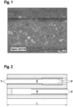
- the Fig. 1 shows a light microscopy image of a filter coated with powder.
- the photo shows a top view of several channel walls in an area of the filter where there is no catalytically active on-wall layer.
- the powder is deposited selectively in the pores of the wall and fills them.
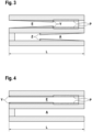
- Fig. 2 shows a schematic of a filter which has a zone of an on-wall layer on the inlet (Y) and outlet side (Z) with a zone length of approx. 60% of the total length and is coated with powder (P) at the end in the uncoated part of the inlet channel (E).
- Fig. 3 shows the same structure of the filter as Fig. 2 with the difference that the two on-wall layers (X, Y) have a coating gradient from the front sides to the center of the carrier.
- Fig. 4 shows a filter with an on-wall layer (X) in the inlet area E, which is charged with a powder (P) in the inlet channel (E).
- Fig. 5 shows a filter with an on-wall layer (Z) in the outlet area A and a zone with an in-wall coating (X), where the powder (P) is deposited in the area of highest permeability.
- Fig. 6 shows a filter in which the walls of the channels are completely activated with an in-wall coating (X) and which has a zone on the inlet side (E) with an on-wall layer (Y) and has been coated with powder (P).
- Fig. 7 shows the same filter as Fig. 5 but without catalytically active in-wall coating (X).
- Fig. 8 shows a schematic of a filter with one on-wall layer each in the inlet (Y) and outlet channel (Z) with a length of approx. 30% of the total length L and an area in the inlet channel (E) exposed to powder (P).
- Fig. 9 shows the results of the investigations into the filtration effect of all described particle filters according to the invention and particle filters according to the state of the art.
- Fig. 10 shows a photo of an opened filter with a zone of an on-wall layer in the inlet channels (grey, left side) and the area exposed to powder (right side)
- Fig. 11 shows enlargements of the filter Fig. 10 with photos of the entrance (1), the middle (2) and the exit (3) of the filter
- Fig. 12 shows a schematic drawing of an advantageous device for applying a powder to the filter.
- the powder 420 or 421 is mixed with the gas under pressure 451 through the atomizer nozzle 440 in the mixing chamber with the gas flow 454 and then sucked or pressed through the filter 430.
- the particles that have passed through are filtered out in the exhaust filter 400.
- the blower 410 ensures the necessary volume flow.
- the exhaust gas is divided into an exhaust gas 452 and a warm circulating gas 453.
- the warm circulating gas 453 is mixed with the fresh gas 450.
- the wall flow filter substrates had a cell density of 46.5 cells per square centimeter and a cell wall thickness of 0.22 mm. They had a porosity of 65% and an average pore size of 18 ⁇ m.
- a coating suspension was applied to the outflow channels.
- coating suspensions were applied to the inflow channels and outflow channels in two steps.
- the filter described in comparative example 3 contains both a coating arranged in the wall and a coating suspension applied to the inflow channels. After applying each coating suspension, the wall flow filters were dried and calcined at 500°C for a period of 4 hours.
- the coating suspension was applied according to the instructions of the person skilled in the art (as in DE102010007499A1 described)
- the catalytically active filters obtained in this way were tested for their fresh filtration efficiency on the engine test bench in the real exhaust gas of an engine that was predominantly (>50% of the operating time) and on average (average lambda over the running time) operated with a stoichiometric air/fuel mixture.
- the driving cycle used was WLTC Class 3.
- the respective filter was installed close to the engine directly after a conventional three-way catalyst. This three-way catalyst was the same for all filters measured. Each filter was subjected to a WLTP. In order to be able to detect the particle emissions during testing, the particle counters were installed before the three-way catalyst and after the particle filter.
- Some catalytically active particulate filters were also subjected to engine test bench aging.
- the aging consisted of overrun cut-off aging with an exhaust gas temperature of 950°C before the catalyst inlet (maximum bed temperature 1030°C).
- the aging time was 38 hours. After aging, the filters were examined for their catalytic activity.
- a noble metal-containing coating suspension containing a cerium/zirconium mixed oxide, a lanthanum-doped aluminum oxide and barium sulfate was applied to 80% of the length of the filter's outlet channel on wall-flow filters with a diameter of 118 mm and a length of 152 mm and then calcined at 500°C.
- the grain size of the oxides in the coating suspension was chosen so that the suspension was applied predominantly to the filter wall (only a small amount of the finest fraction of the coating particles penetrated into the pores of the wall; less than 10%).
- the coating quantity of the VGPF1 after calcination corresponded to 67 g/l, based on the substrate volume.
- a coating suspension containing a cerium/zirconium mixed oxide, a lanthanum-doped aluminum oxide and barium sulfate was applied to 60% of the length of the inlet channel of a wall flow filter with a diameter of 118 mm and a length of 118 mm.
- another coating suspension containing a precious metal was applied to 60% of the length of the outlet channel and then calcined.
- the coating suspension used in the second coating step also contained a cerium/zirconium mixed oxide, a lanthanum-doped aluminum oxide and barium sulfate.
- the grain size of the oxides in the coating suspension was chosen so that the suspension was predominantly applied to the filter wall.
- the coating quantity of VGPF2 after calcination corresponded to 100 g/l, based on the substrate volume.
- a coating suspension containing precious metals which contains a cerium/zirconium mixed oxide, a lanthanum-doped aluminum oxide and barium sulfate, was applied to the entire length of a highly porous wall-flow filter with a diameter of 132 mm and a length of 102 mm.
- the suspension was then calcined.
- the grain size of the oxides in the coating suspension was chosen so that the suspension was predominantly in the filter wall (>90%).
- the coating quantity after calcination corresponded to 100 g/l, based on the substrate volume.
- a second coating step another coating suspension containing precious metals was applied to 60% of the inlet channel and then calcined.
- the coating suspension used in the second coating step also contained a cerium/zirconium mixed oxide, an aluminum oxide doped with lanthanum and barium sulfate.
- the grain size of the oxides in the coating suspension was chosen so that the suspension was applied predominantly to the filter wall.
- the coating quantity of the VGPF3 after calcination corresponded to 132 g/l, based on the substrate volume.
- the inflow channels of the filter were charged with 4 g/l of a highly porous aluminum oxide.
- the relative increase in dynamic pressure of the GPF1 compared to the VGPF1 was 8.6 mbar.
- the filter GPF1 described in Example 1 is in Fig. 7 outlined.
- the inflow channels of the filter were charged with 0.2 g/l of a high-melting pyrogenic aluminum oxide.
- the relative increase in dynamic pressure of the GPF1 compared to the VGPF1 was 5 mbar.
- the filter GPF2 described in example 2 is in Fig. 7 outlined.
- the inflow channels of the filter were charged with 10 g/l of a highly porous aluminum oxide.
- the filter GPF3 described in Example 3 is in Fig. 2 outlined.
- the inflow channels of the filter were charged with 4 g/l of a highly porous aluminum oxide.
- the filter GPF4 described in Example 4 is in Fig. 4 outlined.
- the inflow channels of the filter were charged with 7 g/l of a highly porous aluminum oxide.
- the filter GPF5 described in Example 5 is in Fig. 4 outlined.
- Fig. 9 shows filtration values resulting from the raw particle emissions and particle emissions after the respective filter during a WLTP procedure.
- the advantages of the filters GPF1 to GPF5 according to the invention can be clearly observed during the filter effectiveness measurement. Applying a powder to the filter leads to an increase in filtration efficiency of up to 20%. The desired filtration efficiency can be adjusted by the amount of powder used.
- the GPF4 and GPF5 particulate filters were subjected to engine test bench aging and a subsequent measurement of the "light-off" starting behavior.
- Table 1 contains the temperatures T 50 at which 50% of the component in question is converted.
- Table 1 contains the light-off data for the aged filters VGPF3, GPF4 and GPF5.
- Table 1 T 50 HC stöch T 50 CO stoch T 50 NOx stoch VGPF3 381 398 395 GPF4 386 401 401 GPF5 383 401 402
Landscapes
- Chemical & Material Sciences (AREA)
- Engineering & Computer Science (AREA)
- Chemical Kinetics & Catalysis (AREA)
- Physics & Mathematics (AREA)
- Geometry (AREA)
- Combustion & Propulsion (AREA)
- Mechanical Engineering (AREA)
- General Engineering & Computer Science (AREA)
- Materials Engineering (AREA)
- Organic Chemistry (AREA)
- Ceramic Engineering (AREA)
- Manufacturing & Machinery (AREA)
- Structural Engineering (AREA)
- Catalysts (AREA)
- Filtering Materials (AREA)
- Exhaust Gas Treatment By Means Of Catalyst (AREA)
Applications Claiming Priority (3)
| Application Number | Priority Date | Filing Date | Title |
|---|---|---|---|
| DE102018127955.8A DE102018127955A1 (de) | 2018-11-08 | 2018-11-08 | Katalytisch aktiver Partikelfilter mit hoher Filtrationseffizienz |
| EP19801525.7A EP3877633B1 (fr) | 2018-11-08 | 2019-11-07 | Filtre à particules catalytiquement actif ayant une efficacité de filtration élevée |
| PCT/EP2019/080479 WO2020094760A1 (fr) | 2018-11-08 | 2019-11-07 | Filtre à particules catalytiquement actif ayant une efficacité de filtration élevée |
Related Parent Applications (2)
| Application Number | Title | Priority Date | Filing Date |
|---|---|---|---|
| EP19801525.7A Division-Into EP3877633B1 (fr) | 2018-11-08 | 2019-11-07 | Filtre à particules catalytiquement actif ayant une efficacité de filtration élevée |
| EP19801525.7A Division EP3877633B1 (fr) | 2018-11-08 | 2019-11-07 | Filtre à particules catalytiquement actif ayant une efficacité de filtration élevée |
Publications (2)
| Publication Number | Publication Date |
|---|---|
| EP4509212A2 true EP4509212A2 (fr) | 2025-02-19 |
| EP4509212A3 EP4509212A3 (fr) | 2025-04-09 |
Family
ID=68531533
Family Applications (2)
| Application Number | Title | Priority Date | Filing Date |
|---|---|---|---|
| EP19801525.7A Active EP3877633B1 (fr) | 2018-11-08 | 2019-11-07 | Filtre à particules catalytiquement actif ayant une efficacité de filtration élevée |
| EP24216718.7A Pending EP4509212A3 (fr) | 2018-11-08 | 2019-11-07 | Filtre a particules catalytiquement actif a efficacite de filtration elevee |
Family Applications Before (1)
| Application Number | Title | Priority Date | Filing Date |
|---|---|---|---|
| EP19801525.7A Active EP3877633B1 (fr) | 2018-11-08 | 2019-11-07 | Filtre à particules catalytiquement actif ayant une efficacité de filtration élevée |
Country Status (5)
| Country | Link |
|---|---|
| US (2) | US11566548B2 (fr) |
| EP (2) | EP3877633B1 (fr) |
| CN (2) | CN112996990B (fr) |
| DE (1) | DE102018127955A1 (fr) |
| WO (1) | WO2020094760A1 (fr) |
Families Citing this family (26)
| Publication number | Priority date | Publication date | Assignee | Title |
|---|---|---|---|---|
| EP3505246B1 (fr) * | 2017-12-19 | 2019-10-23 | Umicore Ag & Co. Kg | Filtre à particules à effet catalityque actif |
| EP3505245B1 (fr) | 2017-12-19 | 2019-10-23 | Umicore Ag & Co. Kg | Filtre à particules à effet catalytique actif |
| EP3501648B1 (fr) | 2017-12-19 | 2023-10-04 | Umicore Ag & Co. Kg | Filtre à particules catalityquement actif |
| DE102018111246A1 (de) * | 2018-05-09 | 2019-11-14 | Umicore Ag & Co. Kg | Verfahren zum Beschichten eines Wandflussfilters |
| DE102018127955A1 (de) | 2018-11-08 | 2020-05-14 | Umicore Ag & Co. Kg | Katalytisch aktiver Partikelfilter mit hoher Filtrationseffizienz |
| DE102018127953B4 (de) | 2018-11-08 | 2025-03-20 | Umicore Ag & Co. Kg | Wandflussfilter mit hoher Filtrationseffizienz |
| DE102018127957A1 (de) | 2018-11-08 | 2020-05-14 | Umicore Ag & Co. Kg | Partikelfilter mit mehreren Beschichtungen |
| WO2020200398A1 (fr) | 2019-03-29 | 2020-10-08 | Umicore Ag & Co. Kg | Filtre à particules à activité catalytique |
| GB201911702D0 (en) | 2019-08-15 | 2019-10-02 | Johnson Matthey Plc | Particulate filters |
| DE102020203924A1 (de) | 2020-03-26 | 2021-09-30 | Hug Engineering Ag | Formkörper, Verbundkörper, Verfahren zur Herstellung eines Formkörpers und Verfahren zur Herstellung eines Verbundkörpers |
| CN116847918A (zh) * | 2020-12-01 | 2023-10-03 | 康宁股份有限公司 | 可清洗的过滤器主体以及生产方法 |
| EP4015067A1 (fr) * | 2020-12-15 | 2022-06-22 | UMICORE AG & Co. KG | Filtre à particules catalytiquement actif à efficacité de filtration élevée |
| EP4015064B1 (fr) * | 2020-12-15 | 2025-01-22 | Umicore AG & Co. KG | Filtre à particules catalytiquement actif à efficacité de filtration élevée |
| EP4015065B1 (fr) * | 2020-12-15 | 2025-02-26 | Umicore AG & Co. KG | Filtre à particules catalytiquement actif à efficacité de filtration élevée |
| EP4015066A1 (fr) * | 2020-12-15 | 2022-06-22 | UMICORE AG & Co. KG | Filtre à particules catalytiquement actif à efficacité de filtration élevée |
| JP7798799B2 (ja) * | 2020-12-16 | 2026-01-14 | ユミコア日本触媒株式会社 | 微粒子フィルタ、内燃機関の排ガスから粒子状物質を除去する方法、及び微粒子フィルタの製造方法 |
| JP7717468B2 (ja) * | 2021-02-16 | 2025-08-04 | 株式会社キャタラー | 排ガス浄化用触媒 |
| EP4063003A1 (fr) | 2021-03-23 | 2022-09-28 | UMICORE AG & Co. KG | Filtre pour le post-traitement de gaz d'échappement de moteurs à combustion interne |
| DE102021125536A1 (de) * | 2021-10-01 | 2023-04-06 | Umicore Ag & Co. Kg | Katalytisch aktiver Partikelfilter mit hoher Filtrationseffizienz |
| CN114575966B (zh) * | 2022-02-24 | 2023-03-28 | 中自环保科技股份有限公司 | 一种汽油机颗粒捕集催化器及其制备方法 |
| EP4293207B1 (fr) * | 2022-06-14 | 2025-02-26 | Volvo Truck Corporation | Système de moteur comprenant un moteur à combustion d'hydrogène et un système de post-traitement des gaz d'échappement |
| DE102022002854A1 (de) * | 2022-08-05 | 2024-02-08 | Umicore Ag & Co. Kg | Katalytisch aktiver Partikelfilter mit hoher Filtrationseffizienz und Oxidationsfunktion |
| JP2025531356A (ja) * | 2022-09-27 | 2025-09-19 | ビーエーエスエフ モバイル エミッションズ カタリスツ エルエルシー | 触媒化微粒子フィルタ |
| EP4374952A1 (fr) * | 2022-11-28 | 2024-05-29 | Johnson Matthey Public Limited Company | Revetements sur un article monolithique |
| EP4420764B1 (fr) * | 2023-02-23 | 2025-07-30 | Johnson Matthey Public Limited Company | Filtre catalytique pour écoulement sur paroi |
| CN116921189A (zh) * | 2023-07-18 | 2023-10-24 | 同济大学 | 一种cdpf催化剂涂覆方法 |
Citations (21)
| Publication number | Priority date | Publication date | Assignee | Title |
|---|---|---|---|---|
| US4609563A (en) | 1985-02-28 | 1986-09-02 | Engelhard Corporation | Metered charge system for catalytic coating of a substrate |
| WO1999047260A1 (fr) | 1998-03-19 | 1999-09-23 | Johnson Matthey Public Limited Company | Appareil de revetement de support monolithique et son procede de fabrication |
| US6478874B1 (en) | 1999-08-06 | 2002-11-12 | Engelhard Corporation | System for catalytic coating of a substrate |
| EP1136462B1 (fr) | 2000-03-23 | 2004-08-04 | Umicore AG & Co. KG | Procédé de revêtement partiel d'un corps de support |
| WO2005016497A1 (fr) | 2003-08-05 | 2005-02-24 | Engelhard Corporation | Systeme de traitement d'emissions et procede d'utilisation d'un filtre a reduction catalytique selective (scr) |
| WO2010015573A2 (fr) | 2008-08-06 | 2010-02-11 | Basf Se | Dispositif et procédé de positionnement avec une table d'indexage rotative pour des catalyseurs pour automobile et chimiques à base de monolithe |
| DE102010007499A1 (de) | 2010-02-09 | 2011-08-11 | Umicore AG & Co. KG, 63457 | Volumetrische Beschichtungsanordnung |
| WO2011151711A1 (fr) | 2010-06-02 | 2011-12-08 | Johnson Matthey Public Limited Company | Filtre à particules diesel |
| EP2415522A1 (fr) | 2009-04-03 | 2012-02-08 | Cataler Corporation | Procédé et dispositif de fabrication d'un catalyseur de contrôle d'émission de gaz d'échappement et buse utilisée avec le dispositif |
| WO2012030534A1 (fr) | 2010-09-01 | 2012-03-08 | Dow Global Technologies Llc | Procédé pour l'application d'une couche de discrimination sur des filtres poreux en céramique via des assemblages poreux préfabriqués en suspension dans un gaz |
| EP2502661A2 (fr) | 2011-03-25 | 2012-09-26 | NGK Insulators, Ltd. | Filtre en nid d'abeille et son procédé de fabrication |
| US8277880B2 (en) | 2010-04-22 | 2012-10-02 | Ngk Insulators, Ltd. | Method for manufacturing plugged honeycomb structure |
| US8388721B2 (en) | 2006-11-30 | 2013-03-05 | Hitachi Metals, Ltd. | Ceramic honeycomb filter and its production method |
| EP2521618B1 (fr) | 2010-01-04 | 2013-08-28 | Johnson Matthey PLC | Procédé de revêtement d'un substrat monolithique avec un constituant de catalyseur |
| JP5378659B2 (ja) | 2007-06-07 | 2013-12-25 | 株式会社キャタラー | 貴金属担持方法 |
| EP2727640A1 (fr) | 2012-11-06 | 2014-05-07 | Fraunhofer-Gesellschaft zur Förderung der angewandten Forschung e.V. | Filtre à particules |
| EP2502662B1 (fr) | 2011-03-24 | 2014-06-11 | NGK Insulators, Ltd. | Filtre en nid d'abeille et son procédé de fabrication |
| JP2014205108A (ja) | 2013-04-12 | 2014-10-30 | 株式会社キャタラー | スラリー塗布装置 |
| WO2015049110A1 (fr) | 2013-10-03 | 2015-04-09 | Umicore Ag & Co. Kg | Système de post-traitement de gaz d'échappement |
| EP1789190B1 (fr) | 2004-08-21 | 2017-06-14 | Umicore AG & Co. KG | Procede pour revetir un filtre a ecoulement sur paroi d'une composition de revetement |
| WO2018115900A1 (fr) | 2016-12-23 | 2018-06-28 | Johnson Matthey Public Limited Company | Filtre à particules d'essence |
Family Cites Families (58)
| Publication number | Priority date | Publication date | Assignee | Title |
|---|---|---|---|---|
| US108408A (en) | 1870-10-18 | Improvement in cutting and engraving stone, metal, glass | ||
| US1967235A (en) | 1931-09-08 | 1934-07-24 | Karl A Ferkel | Method and apparatus for production of metal oxides |
| US2488440A (en) | 1946-11-30 | 1949-11-15 | Du Pont | Titanium dioxide pigment production |
| BE508951A (fr) | 1951-02-07 | |||
| DE952891C (de) | 1954-01-23 | 1956-11-22 | Degussa | Verfahren zur Herstellung von feinverteilten Metalloxyden und deren Gemischen |
| JPH01151706A (ja) * | 1987-12-08 | 1989-06-14 | Toyota Central Res & Dev Lab Inc | 可燃性微粒子と窒素酸化物を除去するための触媒及びフィルター |
| DE4225970C1 (de) | 1991-10-24 | 1994-04-07 | Degussa | Verfahren und Vorrichtung zur gleichmäßigen und reproduzierbaren Beschichtung von Wabenkörpern mit einem Beschichtungspulver |
| CA2254269A1 (fr) | 1997-12-30 | 1999-06-30 | Patrick P. Chen | Systeme de dispersion de particules seches et appareil de regulation de debit connexe |
| US6220791B1 (en) | 1999-03-11 | 2001-04-24 | Board Of Trustees Of The University Of Arkansas | Apparatus and method for the aerosolization of powders |
| DE19921409A1 (de) | 1999-05-08 | 2000-11-09 | Hosokawa Alpine Ag & Co | Luftstrahlsieb zur Korngrößenanalyse und zugehöriger Siebeinsatz |
| EP1181970B1 (fr) | 2000-08-16 | 2004-02-04 | Umicore AG & Co. KG | Catalyseur pour purifier des gaz d'échappement placé près du moteur et son procédé de fabrication |
| WO2002026379A1 (fr) * | 2000-09-29 | 2002-04-04 | Omg Ag & Co. Kg | Filtre catalytique de particules de suie et utilisation de celui-ci afin de traiter des gaz d'echappement pauvres |
| JP3874270B2 (ja) | 2002-09-13 | 2007-01-31 | トヨタ自動車株式会社 | 排ガス浄化フィルタ触媒及びその製造方法 |
| DE10257113A1 (de) | 2002-12-05 | 2004-06-24 | Emitec Gesellschaft Für Emissionstechnologie Mbh | Partikelfalle mit beschichteter Faserlage |
| JP2004275814A (ja) | 2003-03-13 | 2004-10-07 | Nissan Motor Co Ltd | 排ガス浄化触媒、その製造方法及び排ガス浄化装置 |
| US20060086834A1 (en) | 2003-07-29 | 2006-04-27 | Robert Pfeffer | System and method for nanoparticle and nanoagglomerate fluidization |
| US7875250B2 (en) | 2003-12-11 | 2011-01-25 | Umicore Ag & Co. Kg | Exhaust treatment device, and methods of making the same |
| JP2005296935A (ja) | 2004-03-17 | 2005-10-27 | Toyota Central Res & Dev Lab Inc | 排ガスフィルタおよびその製造方法、並びに、排ガス処理装置 |
| WO2008000449A2 (fr) | 2006-06-29 | 2008-01-03 | Umicore Ag & Co. Kg | catalyseur a trois voies |
| JP4926868B2 (ja) * | 2007-02-09 | 2012-05-09 | イビデン株式会社 | ハニカム構造体および排気ガス処理装置 |
| US8158195B2 (en) | 2007-02-09 | 2012-04-17 | Nissan Motor Co., Ltd. | Catalytic converter and manufacturing method thereof |
| EP1974809B1 (fr) | 2007-03-19 | 2010-09-29 | Umicore AG & Co. KG | Catalyseur trois voies à double couche |
| DE102008010388B4 (de) * | 2008-02-21 | 2015-04-16 | Umicore Ag & Co. Kg | Verfahren zur Beschichtung eines Dieselpartikelfilters und damit hergestelltes Dieselpartikelfilter |
| EP2181749B2 (fr) * | 2008-11-04 | 2018-10-03 | Umicore AG & Co. KG | Filtre à particules diesel doté de propriétés de pression dynamique améliorées |
| DE102008055890A1 (de) * | 2008-11-05 | 2010-05-12 | Süd-Chemie AG | Partikelminderung mit kombiniertem SCR- und NH3-Schlupf-Katalysator |
| DE102009010711A1 (de) | 2009-02-27 | 2010-09-30 | Umicore Ag & Co. Kg | Stickoxid-Speicherkatalysator zum Einsatz im Kraftfahrzeug in motornaher Position |
| WO2010110011A1 (fr) | 2009-03-26 | 2010-09-30 | 日本碍子株式会社 | Filtre en nid d'abeilles et son procédé de production |
| US8758695B2 (en) * | 2009-08-05 | 2014-06-24 | Basf Se | Treatment system for gasoline engine exhaust gas |
| JP5597146B2 (ja) | 2010-03-18 | 2014-10-01 | 日本碍子株式会社 | ハニカムフィルタ製造装置 |
| JP5597148B2 (ja) | 2010-03-18 | 2014-10-01 | 日本碍子株式会社 | ハニカムフィルタ製造装置 |
| WO2011128026A1 (fr) * | 2010-04-14 | 2011-10-20 | Umicore Ag & Co. Kg | Filtre à particules diesel revêtu d'un catalyseur de réduction et présentant des propriétés améliorées |
| DE102010015364B4 (de) | 2010-04-17 | 2013-06-27 | Hosokawa Alpine Ag | Luftstrahlsieb |
| WO2012030533A1 (fr) | 2010-09-01 | 2012-03-08 | Dow Global Technologies Llc | Procédé d'application de couche de discrimination sur des filtres céramiques poreux |
| US8591622B2 (en) * | 2010-10-29 | 2013-11-26 | Corning Incorporated | Filter apparatus with porous ceramic plates |
| US20140245724A1 (en) * | 2011-08-26 | 2014-09-04 | Sumitomo Osaka Cement Co., Ltd. | Exhaust purification catalyst, exhaust emissin control device for internal combustion engine, and exhaust gas purification filter |
| EP2832962B1 (fr) | 2012-03-30 | 2016-08-17 | Toyota Jidosha Kabushiki Kaisha | Filtre à particules |
| GB201219600D0 (en) * | 2012-10-31 | 2012-12-12 | Johnson Matthey Plc | Catalysed soot filter |
| JP6158832B2 (ja) * | 2012-12-03 | 2017-07-05 | トヨタ自動車株式会社 | 排気浄化フィルタ |
| JP2014188394A (ja) | 2013-03-26 | 2014-10-06 | Ngk Insulators Ltd | ノズル、及び、そのノズルを用いたハニカムフィルタ製造装置 |
| GB2512648B (en) * | 2013-04-05 | 2018-06-20 | Johnson Matthey Plc | Filter substrate comprising three-way catalyst |
| GB2520776A (en) * | 2013-12-02 | 2015-06-03 | Johnson Matthey Plc | Wall-flow filter comprising catalytic washcoat |
| WO2015121248A1 (fr) | 2014-02-11 | 2015-08-20 | Basf Se | Procédé de traitement de gaz d'échappement diesel utilisant des particules d'oxyde mixte d'oxyde de cérium et d'oxyde de zirconium produites par pyrolyse |
| US9744529B2 (en) | 2014-03-21 | 2017-08-29 | Basf Corporation | Integrated LNT-TWC catalyst |
| JP6024694B2 (ja) | 2014-03-25 | 2016-11-16 | トヨタ自動車株式会社 | 過給機を備えた内燃機関の排気浄化システム |
| CN105561685B (zh) | 2014-10-15 | 2020-10-30 | 康宁股份有限公司 | 蜂窝空气过滤器及其方法 |
| JP6564637B2 (ja) * | 2014-10-09 | 2019-08-21 | 株式会社キャタラー | 排ガス浄化装置 |
| JP2018521258A (ja) * | 2015-05-19 | 2018-08-02 | ハルドール・トプサー・アクチエゼルスカベット | 粒子状物質および有害化合物をエンジン排気ガスから除去するための方法、多機能フィルタおよびシステム |
| GB2542654B (en) * | 2015-06-28 | 2019-12-04 | Johnson Matthey Plc | Catalytic wall-flow filter having a membrane |
| JP6431823B2 (ja) * | 2015-07-13 | 2018-11-28 | 株式会社Soken | 排ガス浄化フィルタ |
| GB2546164A (en) * | 2015-09-30 | 2017-07-12 | Johnson Matthey Plc | Gasoline particulate filter |
| CN108290102A (zh) | 2015-10-30 | 2018-07-17 | 康宁股份有限公司 | 多孔陶瓷过滤器及其制造方法 |
| GB2545747A (en) * | 2015-12-24 | 2017-06-28 | Johnson Matthey Plc | Gasoline particulate filter |
| EP3442687A1 (fr) * | 2016-04-13 | 2019-02-20 | Umicore AG & Co. KG | Filtre à particules pourvu d'un revêtement à effet scr |
| CN110382830A (zh) | 2017-03-23 | 2019-10-25 | 优美科股份公司及两合公司 | 催化活性微粒过滤器 |
| JP7187109B2 (ja) | 2017-10-31 | 2022-12-12 | コーニング インコーポレイテッド | ハニカム体、およびハニカム体を含むパティキュレートフィルタ |
| DE102018127957A1 (de) | 2018-11-08 | 2020-05-14 | Umicore Ag & Co. Kg | Partikelfilter mit mehreren Beschichtungen |
| DE102018127955A1 (de) | 2018-11-08 | 2020-05-14 | Umicore Ag & Co. Kg | Katalytisch aktiver Partikelfilter mit hoher Filtrationseffizienz |
| DE102018127953B4 (de) | 2018-11-08 | 2025-03-20 | Umicore Ag & Co. Kg | Wandflussfilter mit hoher Filtrationseffizienz |
-
2018
- 2018-11-08 DE DE102018127955.8A patent/DE102018127955A1/de active Pending
-
2019
- 2019-11-07 EP EP19801525.7A patent/EP3877633B1/fr active Active
- 2019-11-07 CN CN201980071764.0A patent/CN112996990B/zh active Active
- 2019-11-07 EP EP24216718.7A patent/EP4509212A3/fr active Pending
- 2019-11-07 US US17/292,059 patent/US11566548B2/en active Active
- 2019-11-07 WO PCT/EP2019/080479 patent/WO2020094760A1/fr not_active Ceased
- 2019-11-07 CN CN202311649414.2A patent/CN117432504A/zh active Pending
-
2022
- 2022-12-21 US US18/069,736 patent/US12018605B2/en active Active
Patent Citations (24)
| Publication number | Priority date | Publication date | Assignee | Title |
|---|---|---|---|---|
| US4609563A (en) | 1985-02-28 | 1986-09-02 | Engelhard Corporation | Metered charge system for catalytic coating of a substrate |
| WO1999047260A1 (fr) | 1998-03-19 | 1999-09-23 | Johnson Matthey Public Limited Company | Appareil de revetement de support monolithique et son procede de fabrication |
| EP1064094B1 (fr) | 1998-03-19 | 2002-09-25 | Johnson Matthey Public Limited Company | Appareil de revetement de support monolithique et son procede de fabrication |
| US6478874B1 (en) | 1999-08-06 | 2002-11-12 | Engelhard Corporation | System for catalytic coating of a substrate |
| EP1136462B1 (fr) | 2000-03-23 | 2004-08-04 | Umicore AG & Co. KG | Procédé de revêtement partiel d'un corps de support |
| WO2005016497A1 (fr) | 2003-08-05 | 2005-02-24 | Engelhard Corporation | Systeme de traitement d'emissions et procede d'utilisation d'un filtre a reduction catalytique selective (scr) |
| EP1789190B1 (fr) | 2004-08-21 | 2017-06-14 | Umicore AG & Co. KG | Procede pour revetir un filtre a ecoulement sur paroi d'une composition de revetement |
| US8388721B2 (en) | 2006-11-30 | 2013-03-05 | Hitachi Metals, Ltd. | Ceramic honeycomb filter and its production method |
| JP5378659B2 (ja) | 2007-06-07 | 2013-12-25 | 株式会社キャタラー | 貴金属担持方法 |
| WO2010015573A2 (fr) | 2008-08-06 | 2010-02-11 | Basf Se | Dispositif et procédé de positionnement avec une table d'indexage rotative pour des catalyseurs pour automobile et chimiques à base de monolithe |
| EP2415522A1 (fr) | 2009-04-03 | 2012-02-08 | Cataler Corporation | Procédé et dispositif de fabrication d'un catalyseur de contrôle d'émission de gaz d'échappement et buse utilisée avec le dispositif |
| EP2521618B1 (fr) | 2010-01-04 | 2013-08-28 | Johnson Matthey PLC | Procédé de revêtement d'un substrat monolithique avec un constituant de catalyseur |
| US8794178B2 (en) | 2010-02-09 | 2014-08-05 | Umicore Ag & Co. Kg | Coating method and device |
| DE102010007499A1 (de) | 2010-02-09 | 2011-08-11 | Umicore AG & Co. KG, 63457 | Volumetrische Beschichtungsanordnung |
| US8277880B2 (en) | 2010-04-22 | 2012-10-02 | Ngk Insulators, Ltd. | Method for manufacturing plugged honeycomb structure |
| WO2011151711A1 (fr) | 2010-06-02 | 2011-12-08 | Johnson Matthey Public Limited Company | Filtre à particules diesel |
| EP2576021B1 (fr) * | 2010-06-02 | 2014-12-03 | Johnson Matthey Public Limited Company | Filtre à particules diesel |
| WO2012030534A1 (fr) | 2010-09-01 | 2012-03-08 | Dow Global Technologies Llc | Procédé pour l'application d'une couche de discrimination sur des filtres poreux en céramique via des assemblages poreux préfabriqués en suspension dans un gaz |
| EP2502662B1 (fr) | 2011-03-24 | 2014-06-11 | NGK Insulators, Ltd. | Filtre en nid d'abeille et son procédé de fabrication |
| EP2502661A2 (fr) | 2011-03-25 | 2012-09-26 | NGK Insulators, Ltd. | Filtre en nid d'abeille et son procédé de fabrication |
| EP2727640A1 (fr) | 2012-11-06 | 2014-05-07 | Fraunhofer-Gesellschaft zur Förderung der angewandten Forschung e.V. | Filtre à particules |
| JP2014205108A (ja) | 2013-04-12 | 2014-10-30 | 株式会社キャタラー | スラリー塗布装置 |
| WO2015049110A1 (fr) | 2013-10-03 | 2015-04-09 | Umicore Ag & Co. Kg | Système de post-traitement de gaz d'échappement |
| WO2018115900A1 (fr) | 2016-12-23 | 2018-06-28 | Johnson Matthey Public Limited Company | Filtre à particules d'essence |
Non-Patent Citations (11)
| Title |
|---|
| GUTSCH A. ET AL., KONA, no. 20, 2002 |
| H. BENARD, C. R. ACAD. SCI. PARIS SER. IV, vol. 147, no. 839, 1908, pages 147,970 |
| HALL ET AL., SAE, 3 January 1999 (1999-01-03), pages 530 |
| HANS FERKEL ET AL., MTZ - MOTORTECHNISCHE ZEITSCHRIFT, vol. 71, 2010, pages 128 - 133 |
| HINDS, W.: "Aerosol technology: Properties and behavior and measurement of airborne particles", vol. 2, 1999, WILEY |
| LI S., PROGRESS IN ENERGY AND COMBUSTION SCIENCE, no. 55, 2016 |
| MARICQ ET AL., SAE, 1 January 1999 (1999-01-01), pages 530 |
| MATHIS ET AL., ATMOSPHERIC ENVIRONMENT, vol. 38, pages 4347 |
| PATER ALBERS ET AL., CHEMIE IN UNSERER ZEIT, vol. 50, 2016, pages 162 - 171 |
| T. VON KARMAN, NACHR. GES. WISS. GÖTTINGEN, MATH. PHYS. KL., vol. 509, no. 1911, 1912, pages 547 |
| ULRICH G., COMBSUTION SCIENCE AND TECHNOLOGY, vol. 4, 1971 |
Also Published As
| Publication number | Publication date |
|---|---|
| EP3877633B1 (fr) | 2025-03-26 |
| EP4509212A3 (fr) | 2025-04-09 |
| US20230127269A1 (en) | 2023-04-27 |
| CN112996990B (zh) | 2023-12-05 |
| DE102018127955A1 (de) | 2020-05-14 |
| CN112996990A (zh) | 2021-06-18 |
| US11566548B2 (en) | 2023-01-31 |
| CN117432504A (zh) | 2024-01-23 |
| WO2020094760A1 (fr) | 2020-05-14 |
| US12018605B2 (en) | 2024-06-25 |
| EP3877633A1 (fr) | 2021-09-15 |
| US20210396167A1 (en) | 2021-12-23 |
Similar Documents
| Publication | Publication Date | Title |
|---|---|---|
| EP3877633B1 (fr) | Filtre à particules catalytiquement actif ayant une efficacité de filtration élevée | |
| EP3595796B1 (fr) | Procédé destiné à recouvrir un filtre à écoulement de paroi | |
| EP3501648B1 (fr) | Filtre à particules catalityquement actif | |
| EP2181749B2 (fr) | Filtre à particules diesel doté de propriétés de pression dynamique améliorées | |
| DE102018110804B4 (de) | Beschichteter Wandflussfilter | |
| DE102018127953B4 (de) | Wandflussfilter mit hoher Filtrationseffizienz | |
| DE102019100099B4 (de) | Verfahren zur Herstellung von katalytisch aktiven Wandflussfiltern, katalytisch aktiver Wandflussfilter und dessen Verwendung | |
| EP3505245B1 (fr) | Filtre à particules à effet catalytique actif | |
| EP3505246B1 (fr) | Filtre à particules à effet catalityque actif | |
| WO2020094766A1 (fr) | Filtre à particules pourvu de plusieurs revêtements | |
| WO2022129027A1 (fr) | Filtre à particules catalytiquement actif à haut degré de rendement de filtration | |
| EP4015064B1 (fr) | Filtre à particules catalytiquement actif à efficacité de filtration élevée | |
| EP4015065B1 (fr) | Filtre à particules catalytiquement actif à efficacité de filtration élevée | |
| DE102019100097B4 (de) | Verfahren zur Herstellung von katalytisch aktiven Wandflussfiltern | |
| WO2022129023A1 (fr) | Filtre à particules catalytiquement actif ayant un haut degré d'efficacité de filtration | |
| EP4408569A1 (fr) | Filtre à particules catalytiquement actif à grand rendement de filtration | |
| DE102018100833A1 (de) | Verfahren zur Herstellung eines SCR-Katalysators | |
| DE102021107130A1 (de) | Vorrichtung zur Erhöhung der Frischfiltration von Benzinpartikelfiltern | |
| EP4313376A1 (fr) | Filtre à particules pour gaz d'échappement de moteurs à essence |
Legal Events
| Date | Code | Title | Description |
|---|---|---|---|
| PUAI | Public reference made under article 153(3) epc to a published international application that has entered the european phase |
Free format text: ORIGINAL CODE: 0009012 |
|
| STAA | Information on the status of an ep patent application or granted ep patent |
Free format text: STATUS: THE APPLICATION HAS BEEN PUBLISHED |
|
| AC | Divisional application: reference to earlier application |
Ref document number: 3877633 Country of ref document: EP Kind code of ref document: P |
|
| AK | Designated contracting states |
Kind code of ref document: A2 Designated state(s): AL AT BE BG CH CY CZ DE DK EE ES FI FR GB GR HR HU IE IS IT LI LT LU LV MC MK MT NL NO PL PT RO RS SE SI SK SM TR |
|
| REG | Reference to a national code |
Ref country code: DE Ref legal event code: R079 Free format text: PREVIOUS MAIN CLASS: B01J0037020000 Ipc: F01N0003022000 |
|
| PUAL | Search report despatched |
Free format text: ORIGINAL CODE: 0009013 |
|
| AK | Designated contracting states |
Kind code of ref document: A3 Designated state(s): AL AT BE BG CH CY CZ DE DK EE ES FI FR GB GR HR HU IE IS IT LI LT LU LV MC MK MT NL NO PL PT RO RS SE SI SK SM TR |
|
| RIC1 | Information provided on ipc code assigned before grant |
Ipc: B01J 37/02 20060101ALI20250304BHEP Ipc: B01J 23/00 20060101ALI20250304BHEP Ipc: C04B 35/01 20060101ALI20250304BHEP Ipc: B01D 46/24 20060101ALI20250304BHEP Ipc: F01N 3/022 20060101AFI20250304BHEP |
|
| STAA | Information on the status of an ep patent application or granted ep patent |
Free format text: STATUS: REQUEST FOR EXAMINATION WAS MADE |
|
| 17P | Request for examination filed |
Effective date: 20251009 |
|
| STAA | Information on the status of an ep patent application or granted ep patent |
Free format text: STATUS: EXAMINATION IS IN PROGRESS |
|
| 17Q | First examination report despatched |
Effective date: 20260213 |