EP4509370A1 - Dispositif de coussin de sécurité gonflable latéral pour véhicule - Google Patents
Dispositif de coussin de sécurité gonflable latéral pour véhicule Download PDFInfo
- Publication number
- EP4509370A1 EP4509370A1 EP22937545.6A EP22937545A EP4509370A1 EP 4509370 A1 EP4509370 A1 EP 4509370A1 EP 22937545 A EP22937545 A EP 22937545A EP 4509370 A1 EP4509370 A1 EP 4509370A1
- Authority
- EP
- European Patent Office
- Prior art keywords
- occupant
- chamber
- vehicle
- airbag
- upward
- Prior art date
- Legal status (The legal status is an assumption and is not a legal conclusion. Google has not performed a legal analysis and makes no representation as to the accuracy of the status listed.)
- Pending
Links
Images


Classifications
-
- B—PERFORMING OPERATIONS; TRANSPORTING
- B60—VEHICLES IN GENERAL
- B60R—VEHICLES, VEHICLE FITTINGS, OR VEHICLE PARTS, NOT OTHERWISE PROVIDED FOR
- B60R21/00—Arrangements or fittings on vehicles for protecting or preventing injuries to occupants or pedestrians in case of accidents or other traffic risks
- B60R21/02—Occupant safety arrangements or fittings, e.g. crash pads
- B60R21/16—Inflatable occupant restraints or confinements designed to inflate upon impact or impending impact, e.g. air bags
- B60R21/23—Inflatable members
- B60R21/231—Inflatable members characterised by their shape, construction or spatial configuration
- B60R21/23138—Inflatable members characterised by their shape, construction or spatial configuration specially adapted for side protection
-
- B—PERFORMING OPERATIONS; TRANSPORTING
- B60—VEHICLES IN GENERAL
- B60R—VEHICLES, VEHICLE FITTINGS, OR VEHICLE PARTS, NOT OTHERWISE PROVIDED FOR
- B60R21/00—Arrangements or fittings on vehicles for protecting or preventing injuries to occupants or pedestrians in case of accidents or other traffic risks
- B60R21/02—Occupant safety arrangements or fittings, e.g. crash pads
- B60R21/16—Inflatable occupant restraints or confinements designed to inflate upon impact or impending impact, e.g. air bags
- B60R21/23—Inflatable members
- B60R21/231—Inflatable members characterised by their shape, construction or spatial configuration
- B60R21/23138—Inflatable members characterised by their shape, construction or spatial configuration specially adapted for side protection
- B60R2021/23146—Inflatable members characterised by their shape, construction or spatial configuration specially adapted for side protection seat mounted
Definitions
- the present invention relates to a side airbag device of a vehicle, and more particularly, to a side airbag device of a vehicle which protects an occupant by preventing collision between occupants upon side collision of the vehicle.
- a vehicular airbag device is a safety device that protects a passenger by injecting gas into an airbag according to a signal of an impact detection sensor upon vehicle collision, and rapidly inflating the airbag.
- Such an airbag device is installed in a steering wheel, a dashboard, a seat, a sidewall, etc. provided in a vehicle, and protects an occupant by being inflated toward a front side or a side of the occupant upon vehicle collision.
- a vehicle may be provided with a frontal airbag which is deployed in front of a driver seat and a passenger seat, a curtain airbag and a side airbag which are deployed from where side collision occurs (hereinafter, referred to as a 'collision side') to protect a passenger, and a knee airbag for protecting passenger's knee.
- a frontal airbag which is deployed in front of a driver seat and a passenger seat
- a curtain airbag and a side airbag which are deployed from where side collision occurs hereinafter, referred to as a 'collision side'
- a knee airbag for protecting passenger's knee.
- the side airbag may include a near side airbag which is inflated and deployed between a passenger and a vehicular configuration member like a door, and protects an occupant from the vehicular configuration member protruding inwards from an impact by side collision, and a far-side airbag or a center side airbag which restricts movement of an occupant moving to the inside of a vehicle due to reaction to side collision.
- the side airbag must entirely protect the side of the occupant's body, from the head to the lower body.
- the occupant's posture is not constantly fixed in one position.
- the side airbag when the occupant is in the normal seating position, the side airbag must avoid interference with the curtain airbag during deployment, so as not to hinder the deployment of the curtain airbag.
- the thickness and pressure provided on the upper part of the side airbag may exert impact on the occupant's chest, potentially increasing the risk of rib damage.
- the side airbag must still sufficiently protect the occupant's head, which is moved backward and upward from the backrest.
- An object of the present invention is to solve the problems as described above, and is to provide a side airbag device for a vehicle which may safely protect an occupant by inflating and deploying an airbag toward a side of the occupant in the event of side collision of the vehicle.
- Another object of the present invention is to provide a side airbag device for a vehicle which may safely protect the occupant's head by moving the occupant's arm upward upon side collision, thereby expanding an upper chamber of the side airbag upward.
- Another object of the present invention is to provide a side airbag device for a vehicle which may safely protect the occupant's lower and upper body, including the pelvis area to the head, regardless of the occupant's posture.
- a side airbag device of a vehicle includes an airbag cushion which is embedded in a backrest of a seat and is inflated and deployed to correspond to an entire side surface of an upper body of an occupant upon side collision of the vehicle; and an inflater configured to generate a gas by an impact detection signal upon the side collision of the vehicle to supply the gas to the airbag cushion, wherein the airbag cushion has a height to which the airbag cushion is inflated and deployed upward due to contact with an occupant's arm.
- the effect of being able to adjust the height at which the airbag cushion of the side airbag is inflated and deployed upward may be obtained.
- the height to which the airbag cushion inflates upward may be limited to avoid interference with the curtain airbag.
- the occupant's arm may be in contact with the airbag cushion to move upward to expand upward the upper chamber of the airbag cushion.
- the upper chamber may expand to safely protect the occupant's head, even when the occupant is in the reclining posture with the backrest tilted backward by more than 40 degrees.
- an effect may be achieved in that the occupant's lower and upper body, from the pelvis portion to the head, may be safely protected as a whole, regardless of the occupant's posture.
- a side airbag device is embedded in a backrest, and during side collision of the vehicle, an airbag cushion expands and deploys forward, upward, and downward from a side surface of the backrest to correspond to the entire side of an occupant's upper body, thereby safely protecting the occupant.
- a configuration of the side airbag device installed in a driver seat of a normal vehicle will be described, and a direction of facing a front surface of the vehicle with reference to a driver seat will be referred to as a 'forward direction F,' and a direction of facing a rear surface of the vehicle will be referred to as a 'backward direction B'.
- terms indicating directions such as 'left side L,' 'right side R,' 'upward direction U,' and 'downward direction D' are defined to indicate respective directions with reference to the forward direction and the backward direction described above.
- the forward and backward F and B directions of the vehicle may be expressed as a horizontal direction
- the upward and downward U and D directions of the vehicle may be expressed as a vertical direction
- a configuration of a near-side airbag being inflated and deployed between the occupant and a vehicle configuration member such as a door, protecting the occupant from vehicle configuration member protruding inward due to the impact of side collision will be described.
- the present invent ion may also be modified to apply to a far side airbag or center side airbag, which restricts the movement of the occupant moving toward the inside of the vehicle due to the rebound from the side collision.
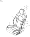
- FIG. 1 is a perspective view of a seat to which a side airbag device for a vehicle is applied, according to a preferred embodiment of the present invention
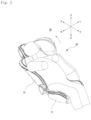
- FIG. 2 is a perspective view of a state in which an airbag cushion is deployed in the side airbag device of the vehicle shown in FIG. 1 .
- a side airbag device of the vehicle includes an airbag cushion 20 embedded in a backrest 12 of a seat 11 and inflated and deployed to correspond to an entire side surface of an upper body of the occupant upon side collision of the vehicle, and an inflater 30 which generates a gas in response to an impact detection signal upon the side collision of the vehicle to supply the gas to the airbag cushion 20.
- the airbag cushion 20 is inflated and deployed from the backrest 12 of the seat 11 in the forward, upward, and downward directions, and is inflated and deployed to correspond to the side of the pelvis and the whole upper body of the occupant, that is, the belly, chest, neck, and head of the occupant.
- the airbag cushion 20 may be inflated and deployed between the occupant and the vehicle configuration member such as the door, to safely protect the occupant from the vehicle configuration member, which protrude inward due to the impact of side collision.
- the airbag cushion 20 may be provided to be inflated and deployed in a substantially circular, oval, or hexahedral shape, and may be inflated and deployed from the side of the occupant toward the upward and forward directions.
- the airbag cushion 20 may be drawn out from a near side of the occupant, i.e., drawn out to the outside of the backrest 12 by cutting along an incision line 13 defined on a left side surface of the backrest 12, as shown in FIGS. 2 and 3 , and may be inflated and deployed forward, upward, and downward toward the side surface of the whole upper body of the occupant.
- the airbag cushion 20 may be provided in a bag shape by joining an edge of an inner panel, which is in contact with the occupant during inflation and deployment, with an edge of an outer panel, provided on the opposite side to the inner panel, such through a sewing method or similar techniques.
- the airbag cushion 20 may be partitioned into a plurality of chambers.
- the airbag cushion 20 may include a central chamber 21 which corresponds to an occupant's chest and upper abdomen, a lower chamber 22 which corresponds to an occupant's pelvis and lower abdomen, and an upper chamber 23 which corresponds to an occupant's head.
- the upper chamber 23 may be vertically rotatable with respect to a rear end in which is connected to the central chamber 21.
- the upper chamber 21 may rotate upward to correspond to a state in which the occupant's head protrudes toward a rear-upper side of the backrest.
- the present invention may be configured to reduce a height of a portion protruding upward in the airbag cushion, compared to that of a portion protruding upward of the cushion applied to the side airbag in the prior art, in order to avoid interference with a curtain airbag during a deployment process of the side airbag.
- the occupant's shoulder and arm may move upward upon contact with the side airbag when the door or other parts intrude into the vehicle due to the side collision.
- the upper chamber may expand upward to correspond to the occupant's head, which is in the rest mode position, by moving the occupant's arm upward.
- the upper chamber may expand to safely protect the occupant's head, even when the occupant is in a reclining posture with the backrest tilted backward by more than 40 degrees.
- FIGS. 3 and 4 are a side view and a front view of the airbag cushion shown in FIG. 2 , respectively, and FIGS. 5 and 6 are a side view and a front view illustrating a state in which the upper chamber of the airbag cushion is rotated upward, respectively.
- FIGS. 3 and 4 show a deployment operation state of the airbag cushion at an initial stage of the collision
- FIGS. 5 and 6 show a deployment operation state of an airbag cushion at a point after a certain amount of time is elapsed following the collision.
- a supply hole 24 may be defined in a central portion of the airbag cushion 20, i.e., in the central chamber 21, which is connected to the inflater 30 to receive the gas upon the side collision of the vehicle.
- the airbag cushion 20 may have a plurality of chamber walls.
- a first chamber wall 25 may be provided between the central chamber 21 and the lower chamber 22, separating the central chamber 21 from the lower chamber 22.
- a second chamber wall 26 may be provided in the central chamber 21, defining a shape of the central chamber 21.
- a third chamber wall 27 may be provided between the central chamber 21 and the upper chamber 23, which partitions the central chamber 21 from the upper chamber 23.
- the first chamber wall 25 may be provided approximately horizontal along the front-rear direction of the airbag cushion 20, or slightly inclined toward the front-lower side of the airbag cushion 20.
- a lower vent 211 which supplies the gas provided to the central chamber 21 to the lower chamber 22, may be defined between the first chamber wall 25 and a rear end of the airbag cushion 20.
- the second chamber wall 26 may be provided in the vertical direction between a rear end of the central chamber 21 and a central portion of the central chamber 21.
- the second chamber wall 26 may extend from an approximately central rear end of the of the inner panel of the airbag cushion 20 to a lower end of the lower chamber 22.
- the central chamber 21 and the lower chamber 22 may be inflated and deployed so that each of the central and front ends has a thickness greater than that of the rear end with respect to the second chamber wall 26.
- the central chamber 21 may be inflated and deployed such that a width in a left-right direction gradually decreases upward from the central portion thereof.
- the occupant's arm when the occupant's arm is in contact with the central chamber 21, the occupant's arm may move upward along an inner surface of the central chamber 21.
- the third chamber wall 27 may partition the central chamber 21 from the upper chamber 23, such that the upper chamber 23 has an approximately ' ⁇ ' shape when viewed from the side.
- the third chamber wall 27 may be inclined forward and downward at a portion in which the central chamber 21 and the upper chamber 23 are connected to each other.
- the third chamber wall 27 may be provided as a non-inflating area that does not inflate during inflation and deployment of the airbag cushion 20 and may have an area larger than that of a space between the upper chamber 23 and the central chamber 21, allowing the upper chamber 23 to expand upward.
- the third chamber wall 27 may remain partially folded during the initial deployment of the airbag cushion 20 and may deploy and expand upward as the upper chamber 23 moves upward due to the movement of the occupant's arm.
- the third chamber wall 27 may define the maximum height to which the upper chamber 23 moves and expands upward.
- the upper chamber and a rear portion of the central chamber may communicate with each other to transfer the gas, and the upper chamber may expand upward in response to the upward movement of the occupant's arm, so as to correspond the head of the occupant in the rest mode posture, thereby safely protecting the occupant's head.
- the airbag cushion 20 may be provided with an external vent (not shown) that discharges the gas inside the airbag cushion 20 to the outside.
- the external vent may be disposed on a front end of the central portion of the central chamber 21.
- the central chamber 21 may gradually release the gas therein through the external vent over time, allowing a deployment pressure to be regulated.
- the gas generated from the inflater 30 may be sequentially supplied to the lower and upper chambers 22 and 23 through the central chamber 21 to inflate and deploy the airbag.
- the airbag may avoid interference with the curtain airbag 40 on a side of a vehicle's roof rail.
- the height to which the airbag cushion inflates upward may be limited to avoid interference with the curtain airbag.
- the occupant may move toward the collision side while being in contact with the airbag cushion 20.
- the occupant's arm may move upward along the inner surface of the central chamber 21 of the airbag cushion 20.
- the upper chamber 23 may move upward higher than a height shown in FIGS. 3 and 4 to expand.
- the upper chamber of the airbag cushion may expand upward due to the movement of the occupant's arm.
- the side airbag according to the present invention may still sufficiently protect the occupant's head, which is moved backward and upward from the backrest.
- the plurality of chamber walls which partition the one airbag cushion into the plurality of chambers may be provided to create the non-inflating area, and the gas provided to the central chamber of the airbag cushion may be supplied to the upper chamber to protect the occupant's head, to reduce the amount of gas required for airbag cushion deployment, thereby minimizing the capacity of the inflater .
- the present invention may be applied to a vehicle's side airbag device technology, which expands the upper chamber of the side airbag upward upon contact with the occupant's arm, thereby safely protecting the occupant's head.
Landscapes
- Engineering & Computer Science (AREA)
- Mechanical Engineering (AREA)
- Air Bags (AREA)
Applications Claiming Priority (1)
| Application Number | Priority Date | Filing Date | Title |
|---|---|---|---|
| PCT/KR2022/005472 WO2023200032A1 (fr) | 2022-04-15 | 2022-04-15 | Dispositif de coussin de sécurité gonflable latéral pour véhicule |
Publications (2)
| Publication Number | Publication Date |
|---|---|
| EP4509370A1 true EP4509370A1 (fr) | 2025-02-19 |
| EP4509370A4 EP4509370A4 (fr) | 2026-01-28 |
Family
ID=88329697
Family Applications (1)
| Application Number | Title | Priority Date | Filing Date |
|---|---|---|---|
| EP22937545.6A Pending EP4509370A4 (fr) | 2022-04-15 | 2022-04-15 | Dispositif de coussin de sécurité gonflable latéral pour véhicule |
Country Status (5)
| Country | Link |
|---|---|
| US (1) | US12606117B2 (fr) |
| EP (1) | EP4509370A4 (fr) |
| JP (1) | JP2025512365A (fr) |
| CN (1) | CN119137018A (fr) |
| WO (1) | WO2023200032A1 (fr) |
Family Cites Families (31)
| Publication number | Priority date | Publication date | Assignee | Title |
|---|---|---|---|---|
| DE19538657A1 (de) * | 1995-10-17 | 1997-04-24 | Trw Repa Gmbh | Gassack-Seitenaufprall-Schutzeinrichtung |
| JPH09136595A (ja) * | 1995-11-15 | 1997-05-27 | Tokai Rika Co Ltd | 側突用エアバッグ装置 |
| JP3430835B2 (ja) * | 1996-09-26 | 2003-07-28 | 三菱自動車工業株式会社 | エアバック装置 |
| KR19980022289U (ko) * | 1996-10-26 | 1998-07-15 | 양재신 | 사이드 에어백 |
| JPH10297409A (ja) * | 1997-02-27 | 1998-11-10 | Toyoda Gosei Co Ltd | 側面衝突用エアバッグ |
| DE69838939T2 (de) * | 1997-09-19 | 2008-04-30 | Nissan Motor Co., Ltd., Yokohama | Vorrichtung zum schützen der insassen eines fahrzeuges bei einem seitenaufprall |
| US6155598A (en) * | 1999-09-01 | 2000-12-05 | Trw Vehicle Safety Systems Inc. | Side impact air bag |
| US20040183285A1 (en) * | 2003-01-29 | 2004-09-23 | Mazda Motor Corporation | Airbag device for vehicle |
| JP2007530364A (ja) * | 2004-03-30 | 2007-11-01 | キー セーフティー システムズ、 インコーポレイテッド | サイドエアバッグモジュール |
| JP4928796B2 (ja) * | 2006-02-07 | 2012-05-09 | 本田技研工業株式会社 | エアバッグ装置 |
| JP5120599B2 (ja) * | 2006-06-20 | 2013-01-16 | マツダ株式会社 | サイドエアバッグ装置 |
| US7954846B2 (en) * | 2009-02-06 | 2011-06-07 | Mazda Motor Corporation | Interior structure of vehicle |
| JP5534708B2 (ja) * | 2009-04-22 | 2014-07-02 | マツダ株式会社 | サイドエアバッグ装置およびそのバッグ部の折畳み方法 |
| US8322747B2 (en) * | 2010-07-14 | 2012-12-04 | Autoliv Asp, Inc. | Inflatable airbag assemblies with arm-manipulating side airbags |
| DE102011113922A1 (de) * | 2011-09-21 | 2013-03-21 | GM Global Technology Operations LLC (n. d. Gesetzen des Staates Delaware) | Airbagvorrichtung für ein Fahrzeug, Verfahren zum Überführen eines Airbags der Airbagvorrichtung in einen kompakten Zustand und Fahrzeug mit der Airbagvorrichtung |
| DE102013015141B4 (de) * | 2013-09-13 | 2017-08-10 | Trw Automotive Gmbh | Verfahren zum Schützen eines Fahrzeuginsassen sowie Gassack |
| US9707922B2 (en) * | 2014-12-10 | 2017-07-18 | Tk Holdings Inc. | Airbag module |
| KR101708213B1 (ko) | 2015-07-22 | 2017-02-20 | 아우토리브 디벨롭먼트 아베 | 측면 충돌용 에어백 |
| KR101739857B1 (ko) | 2015-11-19 | 2017-05-25 | 아우토리브 디벨롭먼트 아베 | 측면 충돌용 에어백 |
| KR101866083B1 (ko) | 2016-11-01 | 2018-06-11 | 현대자동차주식회사 | 자립형 센터 사이드 에어백 |
| JP6880954B2 (ja) * | 2017-04-07 | 2021-06-02 | トヨタ自動車株式会社 | 車両用サイドエアバッグ装置及びその製造方法 |
| KR102352139B1 (ko) * | 2017-05-19 | 2022-01-18 | 아우토리브 디벨롭먼트 아베 | 사이드 에어백 장치 |
| JP6332527B2 (ja) | 2017-05-31 | 2018-05-30 | トヨタ自動車株式会社 | 車両用サイドエアバッグ装置 |
| KR102373411B1 (ko) * | 2019-06-04 | 2022-03-14 | 현대자동차주식회사 | 차량의 시트 에어백 |
| WO2020255817A1 (fr) * | 2019-06-20 | 2020-12-24 | 芦森工業株式会社 | Dispositif de coussin de sécurité gonflable latéral |
| KR20210002883A (ko) | 2019-07-01 | 2021-01-11 | 아우토리브 디벨롭먼트 아베 | 자동차의 에어백 장치 |
| KR20210119161A (ko) * | 2020-03-24 | 2021-10-05 | 아우토리브 디벨롭먼트 아베 | 자동차의 사이드 에어백 장치 |
| DE102020123842A1 (de) * | 2020-09-14 | 2022-03-17 | Joyson Safety Systems Germany Gmbh | Gassack und Gassackanordnung für ein Fahrzeuginsassen-Rückhaltesystem |
| KR102543716B1 (ko) * | 2021-04-07 | 2023-06-16 | 아우토리브 디벨롭먼트 아베 | 자동차의 사이드 에어백 장치 |
| DE102022117213A1 (de) * | 2022-07-11 | 2024-01-11 | Dr. Ing. H.C. F. Porsche Aktiengesellschaft | Kraftfahrzeug und Verfahren zum Betreiben eines Kraftfahrzeugs |
| US11851020B1 (en) * | 2022-12-14 | 2023-12-26 | Ford Global Technologies, Llc | Selectively extendable seat airbag |
-
2022
- 2022-04-15 JP JP2024560258A patent/JP2025512365A/ja active Pending
- 2022-04-15 US US18/855,931 patent/US12606117B2/en active Active
- 2022-04-15 CN CN202280095563.6A patent/CN119137018A/zh active Pending
- 2022-04-15 EP EP22937545.6A patent/EP4509370A4/fr active Pending
- 2022-04-15 WO PCT/KR2022/005472 patent/WO2023200032A1/fr not_active Ceased
Also Published As
| Publication number | Publication date |
|---|---|
| CN119137018A (zh) | 2024-12-13 |
| WO2023200032A1 (fr) | 2023-10-19 |
| US20250249859A1 (en) | 2025-08-07 |
| JP2025512365A (ja) | 2025-04-17 |
| EP4509370A4 (fr) | 2026-01-28 |
| US12606117B2 (en) | 2026-04-21 |
Similar Documents
| Publication | Publication Date | Title |
|---|---|---|
| KR102064844B1 (ko) | 자동차의 에어백 장치 | |
| KR102154182B1 (ko) | 자동차의 에어백 장치 | |
| EP3868612B1 (fr) | Dispositif de coussin gonflable de sécurité pour véhicule | |
| US9403500B2 (en) | Airbag device | |
| EP3900985B1 (fr) | Dispositif de coussin pneumatique latéral, siège de véhicule équipé dudit dispositif, et procédé de fabrication de dispositif de coussin pneumatique latéral | |
| JP6149840B2 (ja) | 車両用ファーサイドエアバッグ装置 | |
| EP3922517B1 (fr) | Dispositif de coussin de sécurité gonflable latéral | |
| US11752965B2 (en) | Side airbag device and method for manufacturing side airbag device | |
| KR101708217B1 (ko) | 차량용 에어백 장치 | |
| KR102388323B1 (ko) | 자동차의 파 사이드 에어백 장치 | |
| US9469267B2 (en) | Airbag device | |
| KR102144753B1 (ko) | 자동차의 센터 사이드 에어백 장치 | |
| KR102755190B1 (ko) | 자동차의 에어백 장치 | |
| KR102729837B1 (ko) | 자동차의 에어백 장치 | |
| EP4212396B1 (fr) | Dispositif coussin de sécurité gonflable pour véhicule | |
| KR102064843B1 (ko) | 자동차의 에어백 장치 | |
| JP7078742B2 (ja) | 車両用シート | |
| KR20220033084A (ko) | 자동차의 에어백 장치 | |
| KR20210119161A (ko) | 자동차의 사이드 에어백 장치 | |
| KR20200075084A (ko) | 자동차의 에어백 장치 | |
| JP7077095B2 (ja) | エアバック展開方法 | |
| EP4163159B1 (fr) | Dispositif de coussin de sécurité gonflable de face cachée de véhicule | |
| KR102543716B1 (ko) | 자동차의 사이드 에어백 장치 | |
| JP2003285709A (ja) | サイドエアバッグ装置 | |
| EP4509370A1 (fr) | Dispositif de coussin de sécurité gonflable latéral pour véhicule |
Legal Events
| Date | Code | Title | Description |
|---|---|---|---|
| STAA | Information on the status of an ep patent application or granted ep patent |
Free format text: STATUS: THE INTERNATIONAL PUBLICATION HAS BEEN MADE |
|
| PUAI | Public reference made under article 153(3) epc to a published international application that has entered the european phase |
Free format text: ORIGINAL CODE: 0009012 |
|
| STAA | Information on the status of an ep patent application or granted ep patent |
Free format text: STATUS: REQUEST FOR EXAMINATION WAS MADE |
|
| 17P | Request for examination filed |
Effective date: 20241024 |
|
| AK | Designated contracting states |
Kind code of ref document: A1 Designated state(s): AL AT BE BG CH CY CZ DE DK EE ES FI FR GB GR HR HU IE IS IT LI LT LU LV MC MK MT NL NO PL PT RO RS SE SI SK SM TR |
|
| DAV | Request for validation of the european patent (deleted) | ||
| DAX | Request for extension of the european patent (deleted) | ||
| A4 | Supplementary search report drawn up and despatched |
Effective date: 20260108 |
|
| RIC1 | Information provided on ipc code assigned before grant |
Ipc: B60R 21/231 20110101AFI20251223BHEP Ipc: B60R 21/207 20060101ALI20251223BHEP Ipc: B60R 21/233 20060101ALI20251223BHEP |