EP4509664A1 - Robinet de sortie protégé contre le gel - Google Patents
Robinet de sortie protégé contre le gel Download PDFInfo
- Publication number
- EP4509664A1 EP4509664A1 EP24193012.2A EP24193012A EP4509664A1 EP 4509664 A1 EP4509664 A1 EP 4509664A1 EP 24193012 A EP24193012 A EP 24193012A EP 4509664 A1 EP4509664 A1 EP 4509664A1
- Authority
- EP
- European Patent Office
- Prior art keywords
- housing
- frost
- valve
- spindle
- actuating device
- Prior art date
- Legal status (The legal status is an assumption and is not a legal conclusion. Google has not performed a legal analysis and makes no representation as to the accuracy of the status listed.)
- Pending
Links
Images

Classifications
-
- E—FIXED CONSTRUCTIONS
- E03—WATER SUPPLY; SEWERAGE
- E03B—INSTALLATIONS OR METHODS FOR OBTAINING, COLLECTING, OR DISTRIBUTING WATER
- E03B9/00—Methods or installations for drawing-off water
- E03B9/02—Hydrants; Arrangements of valves therein; Keys for hydrants
- E03B9/025—Taps specially designed for outdoor use, e.g. wall hydrants, sill cocks
-
- E—FIXED CONSTRUCTIONS
- E03—WATER SUPPLY; SEWERAGE
- E03C—DOMESTIC PLUMBING INSTALLATIONS FOR FRESH WATER OR WASTE WATER; SINKS
- E03C1/00—Domestic plumbing installations for fresh water or waste water; Sinks
- E03C1/02—Plumbing installations for fresh water
- E03C1/04—Water-basin installations specially adapted to wash-basins or baths
- E03C1/0412—Constructional or functional features of the faucet handle
Definitions
- the present invention relates to a frost-proof outlet fitting with a valve housing which forms a valve seat, an outlet housing and an intermediate spindle which is accommodated in an intermediate pipe which connects the outlet housing to the valve housing.
- the intermediate spindle positions a valve body arranged within the valve housing relative to the valve seat.
- An actuating device is assigned to the side of the intermediate spindle assigned to the outlet housing.
- Such a frost-proof outlet fitting is available, for example, from the DE 10 2008 009 081 A1 , the EP 1 122 476 , EP 2 479 462 A2 or the DE 200 01 883 U1 , dem DE 298 20 782 U1 or the DE 20 2015 006 027 U1 known.
- the present invention is based on the problem of specifying a frost-proof outlet fitting of the type mentioned at the beginning, which has a higher usability than known frost-proof outlet fittings.
- the present invention provides an actuating device that is specially adapted.
- the actuating device is adapted in such a way that the intermediate spindle can be moved translationally by the actuating device in a first mode and rotated, i.e. moved radially, in a second mode.
- the actuating device is adapted in such a way that the first mode can be initiated by the actuating device independently of the second mode.
- the solution according to the invention allows a further mode in which the intermediate spindle is also rotated due to the actuating device, independently of the translational movement.
- This makes it possible to initiate a rotary movement at the free end of the intermediate spindle and in the area of the valve housing, which creates a possibility that goes beyond simply shutting off the fitting.
- the rotary relative movement can bring another supply branch for fluid to be discharged from the outlet fitting into communication with the outlet fitting in order to selectively discharge one or the other fluid from the outlet fitting.
- the intermediate spindle can be connected to another shaft at its end on the valve housing side in a rotationally fixed manner but movable in the longitudinal direction of the intermediate spindle. This shaft alone thus mediates the rotary movement.
- the frost-proof fitting according to the invention usually follows a structure in which the frost-proof outlet fitting can be adapted to different wall thicknesses. This is because in the frost-proof outlet fitting, the valve housing and the valve seat are arranged on the warm side, i.e. inside the building or at least assigned to this interior, whereas the outlet housing is exposed on the outside of the building.
- the intermediate spindle and the intermediate pipe form an annular space that is emptied when the fitting is shut off. This prevents the outlet fitting on the cold side of the outlet fitting from freezing at sub-zero temperatures.
- the intermediate pipe and the intermediate spindle are each preferably designed in such a way that they can be easily cut to length as a semi-finished product and adapted for connection to adjacent assemblies with just a few processing steps.
- the intermediate pipe is usually a semi-finished product that can be easily cut to length and connected to the valve housing on the one hand and the outlet housing on the other in a sealing manner by thread cutting, soldering or gluing.
- the connection between the intermediate pipe and the outlet housing is made at the factory using one of the previously mentioned methods, for example.
- the adaptation to the variable wall thickness of the building is preferably done by cutting the intermediate pipe to length.
- the intermediate pipe has an external thread so that the connection to the outlet housing is easy to make on site.
- the outlet housing has a conical internal thread, which then allows a thread-sealing connection.
- the intermediate spindle which must have at least one external thread on one side, usually on the side of the outlet housing, for example, in order to be able to be brought into operative connection with the actuating device.
- the intermediate spindle can also have any other external geometry without a thread, which preferably enables a clamping connection with the actuating device.
- the intermediate spindle then preferably has a round external contour or it has a polygonal external contour.
- the intermediate spindle usually passes through at least the intermediate tube, and usually also through the outlet housing in whole or in part, and is there operatively connected to a spindle nut, which converts a rotary movement of the actuating device into a translatory movement of the intermediate spindle.
- a spindle nut which converts a rotary movement of the actuating device into a translatory movement of the intermediate spindle.
- an axial movement of the intermediate spindle is usually mediated by such a spindle nut alone.
- the intermediate spindle is connected to a mixing head in the region of its end associated with the valve housing.
- This mixing head is used to set a mixing ratio of different media with flow outlets to the respective media.
- the corresponding flow outlets are part of a connection housing, with which the intermediate pipe and the intermediate spindle can be connected in a sealing manner, usually with the valve housing in between.
- the connection housing can be part of the outlet fitting according to the invention.
- the latter is preferably connected to the intermediate spindle in a rotationally fixed manner, but displaceable in the longitudinal direction of the intermediate spindle.
- the mixing head is usually axially fixed, the intermediate spindle is axially displaceable.
- the connecting sleeve usually has a hole facing the valve housing, into which the intermediate pipe can be inserted and connected in a sealing manner.
- the connection can be made using a conventional screw, adhesive or solder connection, for example.
- the length of at least the intermediate pipe can be adjusted to the wall thickness provided on site at this connection or at the opposite outer end.
- connection of the connecting sleeve is preferably made via the previously mentioned connection collar of the connection housing.
- the connecting sleeve can be soldered, screwed or glued to the connection collar.
- the outer peripheral surfaces of the two handles preferably merge seamlessly into one another. This means that the user only perceives a uniform control element in the form of a rotary handle.
- the outer handle is usually assigned to the first mode and forms the first handle of the corresponding development.
- the second handle is located between the first handle and the outlet housing. The user can therefore firmly grip the first handle in a manner known per se in order to open and close the fitting, whereas, for example, the mixing ratio of the different media is adjusted by pivoting a peripheral surface that is provided by the second handle and that, after the outlet fitting has been installed, is located between the first handle and the wall over which the outlet housing protrudes.
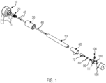
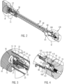
- Reference number 10 designates a connection housing which is partially designed to accommodate a mixer tap 20 which is accommodated in a valve housing 30 and is arranged at one end of an intermediate spindle 40 which extends predominantly coaxially to and in an intermediate pipe 50 which is connected on the side opposite the valve housing 30 to an outlet housing 60 in which an adjusting body 70 is partially accommodated which is axially fixed relative to a spindle nut 80 which can be rotated relative to the adjusting body 70.
- a regulating spindle 90 is threadedly engaged in this spindle nut 80.
- Reference number 100 designates an adjusting lever which is at least partially accommodated in a valve upper part 110, on the free cylindrical end of which an actuating device 120 is at least partially rotatably mounted.
- connection housing 10 has tubular connections 11, in this case for the connection of PWH and PWC (hot drinking water and cold drinking water).
- connection collar 13 and a fastening nozzle 14 protrude from a substantially circular base 12 of the connection housing 10.
- D generally indicates flow passages, including the flow passages D which are recessed in the fastening nozzle 14.
- the connection housing 10 has flow outlets 15 aligned with the intermediate pipe 50.
- a sealing disk 16 rests against an end face of the connection housing 10 forming these flow outlets 15.
- an orifice disk 21 of a mixing head 22 rests against the sealing disk 16, which has an orifice opening 23 and is connected in a rotationally fixed manner to a mixing head shaft 24, which is guided in a sealed manner through a mixing head housing 25 and is connected in a rotationally fixed and axially fixed manner to the intermediate spindle 40 on the side opposite the orifice disk 21.
- the mixing head housing 25 is in turn firmly screwed to the fastening nozzle 14 and sealed against it.
- the intermediate spindle 40 has a mixing head shaft holder 43 at its end facing the mixing head 22 in which the associated end of the mixing head shaft 24 is held in a rotationally fixed manner but movable in the longitudinal direction of the intermediate spindle 40.
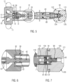
- FIG. 5 As illustrated, an annular space is created between a connecting sleeve 31 of the valve housing 30 and the fastening nozzle 14, through which the water can flow.
- the free end of the intermediate spindle 40 associated with the valve housing 30 is located within the connecting sleeve 31. Between the connecting sleeve 31 and the end of the valve housing 30 facing the outlet housing 60 this tapers conically on the inside to form a valve seat 32.
- the valve seat 32 is formed by an annular surface of the valve housing 30 facing the outlet housing 60.
- Figure 6 illustrates the sealing arrangement of a valve body identified by reference numeral 41, through which the intermediate spindle 40 passes in a sealing manner.
- the intermediate spindle 40 is fixed at least in the axial direction relative to the valve body 41 via an arrangement 42 of locking ring and stuffing box seal and is axially sealed relative to the intermediate spindle 40.
- the intermediate pipe 50 is inserted in a sealed manner in a cylindrical receptacle 33 of the valve housing 30.
- an annular space for the flow from the connection housing 10 to the overflow housing 60 is formed between the intermediate pipe 50 and the intermediate spindle 40.
- the intermediate pipe 50 surrounds the intermediate spindle 40 as a hollow cylindrical component.
- the end of the intermediate pipe 50 opposite the valve housing 30 is connected to the outlet housing 60, which forms an outlet opening 61, which is only indicated schematically, in the connection of which a backflow preventer or a nozzle for a hose connection can be located.
- outlet housing 60 which forms an outlet opening 61, which is only indicated schematically, in the connection of which a backflow preventer or a nozzle for a hose connection can be located.
- outlet housing 60 or intermediate pipe 50 on the one hand or the valve housing 30 on the other hand can be provided with a flange which enables the outlet fitting 60 to be attached to the masonry which is penetrated by the intermediate pipe 50 and the intermediate spindle 40.
- the end of the intermediate spindle 40 associated with the outlet housing 60 is firmly connected to the adjusting body 70.
- the connection is rotationally fixed and fixed in the axial direction.
- the adjusting body 70 has an actuating nozzle 71 that projects in the direction of the actuating device 120 and has a non-rotationally symmetrical outer circumferential surface.
- two flattened contact areas 72 are provided for the corresponding counter surfaces in a driver eye 101 of the adjusting lever 100.
- the adjusting lever 100 is connected to the adjusting body 70 in a rotationally fixed manner.
- the contact area 72 has a sufficient length so that a lever arm 102 of the adjusting lever 100 protruding from the driver eye 101 is held in a partially circumferential slot 111 of the upper part 110, but the actuating body 70 can nevertheless be axially displaced through the driver eye 101 relative to an upper part housing of the valve upper part 110, identified by reference numeral 112, for closing and opening the valve.
- the slot 111 is recessed in a free nozzle 113 of the upper part housing protruding in the direction of the actuating device.
- the spindle nut 80 is fixed in the axial direction via a snap ring 81 in a groove 73 at the free end of the actuating nozzle 71.
- the actuating nozzle 71 has a bore 74 adapted to freely accommodate the actuating end 91 of the regulating spindle 90.
- the spindle nut 80 is axially displaceable, but is held in the upper housing 110 in a rotationally fixed manner.
- FIGS. 5 and 7 show the axial fixing of the regulating spindle 90 relative to the upper part housing 112.
- the free end 92 of the regulating spindle 90 which projects beyond the valve upper part 110, is connected in a rotationally fixed manner to a first handle 121 of the actuating device 120.
- the actuating device 120 also has a second handle 122, which is axially fixed relative to the first handle 121, but is also freely movable in rotation at least to the extent that it allows the rotational movement of the adjusting lever 100 in the slot 111, which is partially recessed in the valve upper part 112.
- the second handle 122 forms a receptacle 123 adapted for the play-free reception of the adjustment lever 100, which is covered over an outer peripheral surface 124 of the second handle 122, but is open towards the outlet housing 60.
- the actuating device 120 can thus be pushed axially onto the regulating spindle 90 in order to fix it axially relative to the first handle 121 and to bring the middle hole of the second handle 122 with little play over the free nozzle 113 of the upper housing 112.
- the nozzle 113 also serves to support the pivoting movement of the second handle 122.
- the outer peripheral surface 124 of the second handle 122 merges seamlessly into the outer peripheral surface 125 of the first handle 121, so that the user has the haptic impression of a uniform actuating device 120 with two different functional areas 121; 122.
- the first handle 121 is turned manually. In a manner known per se, this rotary movement is converted via the valve upper part 110 and the spindle nut 80 into a translatory movement of the intermediate spindle 40, which moves the valve body 41 relative to the valve seat 32 in order to open or close the valve.
- a comparison of the Figures 6 and 10 also shows the resulting relative movement between the mixing head shaft 24 and the intermediate spindle 40 in the longitudinal direction of the same within the mixing head shaft holder 43. In the closed position according to Figure 6 the free end of the mixing head shaft 24 is close to the closed end of the mixing head shaft holder 43, whereas with the outlet fitting open and according to Figure 10 the free end of the mixing head shaft 24 is displaced in the direction of the mixing head 43.
- the mixing head shaft 24 remains stationary in the longitudinal direction of the intermediate spindle 40 due to the fixing of the mixing head 40 to the connection housing 10, whereas the intermediate spindle 40 for opening or closing the outlet fitting moves in its longitudinal direction together with the valve body 41 and relative to the valve seat 32.
- the overlap between the openings in the sealing plate 16 and the orifice opening 23 of the orifice plate 21 changes, whereby the mixing ratio between the fluid flows for the hot and cold drinking water that can be introduced through the two flow inlets 15 is changed.
- the orifice opening 23 can be connected to only one of the flow inlets (cf. Figure 8 ) 15 or with both (cf. Figure 3 ) of the flow inlets 15 are made to overlap.
- the mixing ratio can be adjusted by pivoting the second handle 122.
- the first handle 121 can remain stationary.
Landscapes
- Health & Medical Sciences (AREA)
- Life Sciences & Earth Sciences (AREA)
- Engineering & Computer Science (AREA)
- Hydrology & Water Resources (AREA)
- Public Health (AREA)
- Water Supply & Treatment (AREA)
- Multiple-Way Valves (AREA)
Applications Claiming Priority (1)
| Application Number | Priority Date | Filing Date | Title |
|---|---|---|---|
| DE202023104707.6U DE202023104707U1 (de) | 2023-08-18 | 2023-08-18 | Frostsichere Auslaufarmatur |
Publications (1)
| Publication Number | Publication Date |
|---|---|
| EP4509664A1 true EP4509664A1 (fr) | 2025-02-19 |
Family
ID=92258710
Family Applications (1)
| Application Number | Title | Priority Date | Filing Date |
|---|---|---|---|
| EP24193012.2A Pending EP4509664A1 (fr) | 2023-08-18 | 2024-08-06 | Robinet de sortie protégé contre le gel |
Country Status (2)
| Country | Link |
|---|---|
| EP (1) | EP4509664A1 (fr) |
| DE (1) | DE202023104707U1 (fr) |
Citations (8)
| Publication number | Priority date | Publication date | Assignee | Title |
|---|---|---|---|---|
| DE29820782U1 (de) | 1998-11-20 | 1999-01-14 | Gebr. Kemper GmbH + Co. KG, 57462 Olpe | Frostsichere Armatur, insbesondere Ventil für Wasserleitungen |
| DE20001883U1 (de) | 2000-02-03 | 2000-03-23 | Gebr. Kemper GmbH + Co. KG, 57462 Olpe | Frostsichere Regulier- und Absperrarmatur |
| US7533686B2 (en) * | 2004-01-16 | 2009-05-19 | Moen Incorporated | Mixing sillcock |
| DE102008009081A1 (de) | 2008-02-14 | 2009-08-20 | Gebr. Kemper Gmbh & Co. Kg Metallwerke | Frostsichere Auslaufarmatur |
| US7896024B2 (en) * | 2006-01-10 | 2011-03-01 | Moen Incorporated | Backpressure relief valve |
| EP2479462A2 (fr) | 2011-01-21 | 2012-07-25 | Gebr. Kemper GmbH + Co. KG Metallwerke | Armature sanitaire antigel |
| DE202015006027U1 (de) | 2015-08-26 | 2016-11-29 | Gebr. Kemper Gmbh + Co. Kg Metallwerke | Frostsichere Auslaufarmatur |
| US20200325662A1 (en) * | 2019-04-15 | 2020-10-15 | Prier Products, Inc. | Mixing hydrant |
-
2023
- 2023-08-18 DE DE202023104707.6U patent/DE202023104707U1/de active Active
-
2024
- 2024-08-06 EP EP24193012.2A patent/EP4509664A1/fr active Pending
Patent Citations (9)
| Publication number | Priority date | Publication date | Assignee | Title |
|---|---|---|---|---|
| DE29820782U1 (de) | 1998-11-20 | 1999-01-14 | Gebr. Kemper GmbH + Co. KG, 57462 Olpe | Frostsichere Armatur, insbesondere Ventil für Wasserleitungen |
| DE20001883U1 (de) | 2000-02-03 | 2000-03-23 | Gebr. Kemper GmbH + Co. KG, 57462 Olpe | Frostsichere Regulier- und Absperrarmatur |
| EP1122476A2 (fr) | 2000-02-03 | 2001-08-08 | Gebr. Kemper GmbH + Co. KG | Soupape de réglage et d'arrêt insensible au gel |
| US7533686B2 (en) * | 2004-01-16 | 2009-05-19 | Moen Incorporated | Mixing sillcock |
| US7896024B2 (en) * | 2006-01-10 | 2011-03-01 | Moen Incorporated | Backpressure relief valve |
| DE102008009081A1 (de) | 2008-02-14 | 2009-08-20 | Gebr. Kemper Gmbh & Co. Kg Metallwerke | Frostsichere Auslaufarmatur |
| EP2479462A2 (fr) | 2011-01-21 | 2012-07-25 | Gebr. Kemper GmbH + Co. KG Metallwerke | Armature sanitaire antigel |
| DE202015006027U1 (de) | 2015-08-26 | 2016-11-29 | Gebr. Kemper Gmbh + Co. Kg Metallwerke | Frostsichere Auslaufarmatur |
| US20200325662A1 (en) * | 2019-04-15 | 2020-10-15 | Prier Products, Inc. | Mixing hydrant |
Also Published As
| Publication number | Publication date |
|---|---|
| DE202023104707U1 (de) | 2024-11-28 |
Similar Documents
| Publication | Publication Date | Title |
|---|---|---|
| EP1134468B1 (fr) | Armature sanitaire | |
| EP3420430B1 (fr) | Vanne de mélange thermostatique | |
| CH687038A5 (de) | Steuerpatrone fuer eine Einhebel-Mischarmatur. | |
| EP3074676B1 (fr) | Robinetterie sanitaire | |
| EP1522777A1 (fr) | Robinet mélangeur | |
| DE3725240C2 (fr) | ||
| EP0999389A2 (fr) | Bec verseur orientable avec un robinet mitigeur | |
| DE10239177A1 (de) | Mischbatterie | |
| EP3533941B1 (fr) | Robinet mélangeur | |
| DE19525358C2 (de) | Einhebelmischbatterie zur Unterputzmontage | |
| DE19901654A1 (de) | Eckventil mit Rosettengriff | |
| DE102007009409B4 (de) | Armatur mit Schwenkauslauf | |
| EP0501953B1 (fr) | Melangeur sanitaire | |
| DE202023104707U1 (de) | Frostsichere Auslaufarmatur | |
| EP1462692B1 (fr) | Tête de robinet | |
| EP1846679A1 (fr) | Robinet | |
| EP0139808A1 (fr) | Dispositif d'actionnement à distance de deux ou plusieurs valves de vidange pour éviers, lavabos ou semblables | |
| EP4450720A1 (fr) | Robinetterie de sortie résistante au gel et boîtier de sortie d'une robinetterie | |
| DE102008035971B3 (de) | Verstellelement | |
| EP1706351A1 (fr) | Dispositif pour nettoyer et/ou desinfecter une tete de distribution | |
| DE4138938A1 (de) | Wasserarmatur mit schwenkbarem auslaufrohr | |
| DE4420436A1 (de) | Sanitärarmatur, insbesondere Küchenmischbatterie | |
| DE4324158A1 (de) | Fluidventil | |
| EP0139909B1 (fr) | Elément de construction sanitaire pour régler la distribution ainsi que l'évacuation de l'eau dans ou hors d'une baignoire ou similaire | |
| DE9421996U1 (de) | Anschlußvorrichtung zum Anschluß eines Heizkörpers und Patrone zum Einbau in diese |
Legal Events
| Date | Code | Title | Description |
|---|---|---|---|
| PUAI | Public reference made under article 153(3) epc to a published international application that has entered the european phase |
Free format text: ORIGINAL CODE: 0009012 |
|
| STAA | Information on the status of an ep patent application or granted ep patent |
Free format text: STATUS: THE APPLICATION HAS BEEN PUBLISHED |
|
| AK | Designated contracting states |
Kind code of ref document: A1 Designated state(s): AL AT BE BG CH CY CZ DE DK EE ES FI FR GB GR HR HU IE IS IT LI LT LU LV MC ME MK MT NL NO PL PT RO RS SE SI SK SM TR |
|
| STAA | Information on the status of an ep patent application or granted ep patent |
Free format text: STATUS: REQUEST FOR EXAMINATION WAS MADE |
|
| 17P | Request for examination filed |
Effective date: 20250508 |