EP4509672A1 - Élément de façade et façade d'élément - Google Patents
Élément de façade et façade d'élément Download PDFInfo
- Publication number
- EP4509672A1 EP4509672A1 EP24190510.8A EP24190510A EP4509672A1 EP 4509672 A1 EP4509672 A1 EP 4509672A1 EP 24190510 A EP24190510 A EP 24190510A EP 4509672 A1 EP4509672 A1 EP 4509672A1
- Authority
- EP
- European Patent Office
- Prior art keywords
- sealing
- corner
- facade
- frame
- arm
- Prior art date
- Legal status (The legal status is an assumption and is not a legal conclusion. Google has not performed a legal analysis and makes no representation as to the accuracy of the status listed.)
- Pending
Links
Images



Classifications
-
- E—FIXED CONSTRUCTIONS
- E04—BUILDING
- E04B—GENERAL BUILDING CONSTRUCTIONS; WALLS, e.g. PARTITIONS; ROOFS; FLOORS; CEILINGS; INSULATION OR OTHER PROTECTION OF BUILDINGS
- E04B2/00—Walls, e.g. partitions, for buildings; Wall construction with regard to insulation; Connections specially adapted to walls
- E04B2/88—Curtain walls
- E04B2/96—Curtain walls comprising panels attached to the structure through mullions or transoms
-
- E—FIXED CONSTRUCTIONS
- E04—BUILDING
- E04B—GENERAL BUILDING CONSTRUCTIONS; WALLS, e.g. PARTITIONS; ROOFS; FLOORS; CEILINGS; INSULATION OR OTHER PROTECTION OF BUILDINGS
- E04B2/00—Walls, e.g. partitions, for buildings; Wall construction with regard to insulation; Connections specially adapted to walls
- E04B2/88—Curtain walls
- E04B2/90—Curtain walls comprising panels directly attached to the structure
Definitions
- the present invention relates to a facade element with a frame formed from profiles, on which at least one sealing frame is arranged on an outer circumference, which is formed from corner sealing pieces and sealing profiles connecting the corner sealing pieces, wherein each corner sealing piece has at least one plug-in part inserted in a hollow chamber of one of the sealing profiles and an arm adjoining the plug-in part in the longitudinal direction of the sealing profile outside the sealing profile.
- the DE 20 2017 104 445 U1 discloses a window or a door with a seal that can be assembled using corner sealing elements to form a surrounding sealing frame.
- the use of such a sealing frame can provide a surrounding sealing of a frame.
- deformation can occur in the corner area of the sealing frame, which impairs the tightness if the corner sealing piece is pressed together in two or more directions. This can then lead to compression of the sealing profile, which leads to a wave shape and thus to leaks.
- the DE 20 2019 102 117 U1 reveals facade elements that can be put together to form a modular facade.
- Each facade element includes a surrounding frame to which a filling element is fixed.
- the facade elements can be prefabricated and installed on a building and held together using coupling elements.
- Neighboring facade elements are sealed using sealing profiles that are mounted all the way around the frame of the facade element. Sealing problems can arise with such facade elements, especially in the corner area.
- the facade element according to the invention comprises a frame formed from profiles, on which at least one sealing frame is arranged on an outer circumference, which consists of corner sealing pieces and Sealing profiles are formed, each corner sealing piece having at least one plug-in part inserted into a hollow chamber of one of the sealing profiles and an arm outside the sealing profile which adjoins the plug-in part in the longitudinal direction of the sealing profile, the cross-section of the sealing profile being larger than the cross-section of the arm.
- the smaller cross-section of the arm means that compression in the corner area can be reduced or eliminated when adjacent facade elements are installed, because the smaller cross-section means that no or less shortening of the arm and the sealing profile is necessary when adjacent facade elements are positioned next to each other in a sealed manner.
- one corner sealing piece When the facade elements are installed, one corner sealing piece is loaded in two directions, usually horizontally and vertically, so that the corner sealing piece is also pressed in in the longitudinal direction of the sealing profiles. This leads to deformation of the arms and the sealing profile connected to the respective arm, which leads to a wave shape and thus to leaks.
- the smaller cross-section means that this compression effect can be reduced, which improves sealing.
- the arm extends outwards less in relation to the frame than the adjacent sealing profile.
- the sealing profile is compressed more strongly from the outside to the inside than the arm of the corner sealing piece, so that the other arm of the corner sealing piece is compressed to a lesser extent.
- the cross-section of the sealing profile is preferably at least 10% larger than the cross-section of the arm, for example between 10%-30%.
- the sealing profile can have a constant cross-section and is produced, for example, by extrusion.
- the arm also preferably has a constant cross-section up to the insertion part.
- the arm has only a single hollow chamber, which is smaller than the single hollow chamber of the sealing profile, in order to make the cross-section of the arm, for example, at least 10% smaller.
- Each sealing profile and the arm preferably have only a single hollow chamber in order to have a high degree of elasticity.
- several hollow chambers can also be provided in the arm and the sealing profile.
- Each corner sealing piece preferably has two arms aligned at an angle, in particular these can be aligned at right angles to each other, wherein each arm has an insertion part which can be inserted into a hollow chamber of a sealing profile.
- the sealing profile is tubular and at least one elastic sealing lip is formed on the outside of the sealing profile.
- two spaced sealing lips are formed that protrude on different sides. This means that the sealing profile can provide a seal in several levels when two of the sealing profiles are pressed against one another. A first sealing level is then formed by the tubular section of the two sealing profiles, which are pressed against one another and thus ensure a seal.
- One or two spaced sealing lips can provide further sealing levels, which are formed by the elastic sealing lips that contact one another.
- an opening for drainage and/or ventilation is formed on at least one of the corner sealing pieces.
- an opening for ventilation is provided on an upper corner sealing piece and an opening for drainage is provided on a lower corner sealing piece, which are connected to one another via the hollow chamber of one of the sealing profiles.
- the opening for ventilation is preferably arranged on an inner side, i.e. towards the inside of the building, and the opening for drainage is provided on an outer side of the corner sealing piece.
- the opening for drainage and/or ventilation can be covered with a grid, e.g. gauze, or a closure element.
- the facade element is preferably part of an element facade, with at least two adjacent facade elements being provided on the element facade, each of which contacts one another on one side of the sealing frame for sealing.
- the element facade can comprise facade elements that are surrounded on all four sides by another facade element.
- An element facade comprises at least two facade elements 1, each of which has a frame formed from profiles 2, on which at least one sealing frame 4 is arranged on the outer circumference. Adjacent facade elements 1 can be sealed via the sealing frame 4.
- Each frame formed from profiles 2 comprises at least one sealing frame 4 on the outer circumference, which comprises corner sealing pieces 5 and sealing profiles 6.
- the corner sealing pieces 5 are arranged in the four corners of the frame and are each connected to one another via sealing profiles 6.
- Two sealing frames 4 are provided on each facade element 1, as can be seen from the sectional view of the respective frame. It is also possible to provide only one sealing frame 4 or more than two sealing frames 4.
- the problem is that the corner sealing pieces 5 are compressed in two directions, so that the corner sealing pieces 5 and also the sealing profiles 6 adjoining the corner sealing pieces 5 can be compressed, i.e. shortened in the longitudinal direction, which leads to the formation of waves, which is shown schematically. Such waves 21 can lead to leaks.
- FIG 2 a corner area of a facade element 1 is shown.
- the frame with the profiles 2 has a groove that is open to the outside, into which a base element 7 of the sealing profile 6 is inserted for fixing.
- the sealing profile 6 is tubular and includes a hollow chamber 8. Two flexible sealing lips 9 are formed on an outer side of the sealing profile 6.
- the sealing profile 6 has a height H to the outside in relation to the frame, i.e. it protrudes from the profiles 2.
- the corner sealing piece 5 comprises two arms 11 arranged at an angle to one another, each of which has an insertion part 10 formed on its end.
- the insertion part 10 can be inserted into the hollow chamber 8 of the sealing profile 6 in order to align the arm 11 relative to the sealing profile 6.
- the arm 11 extends the sealing profile 6, whereby the arm 11 has a smaller cross-section than the sealing profile 6, for example a cross-section that is at least 10% smaller.
- the arm 11 extends outwards relative to the frame only by the height h, which is less than the height H of the sealing profile 6, for example by 5%-20% less.
- the second arm 11 also has a lower height h than the adjacent sealing profile 6, so that the corner sealing pieces 5 each have a smaller outward extension than the sealing profiles 6. This lower height reduces the formation of waves in the corner area, which leads to better sealing.
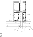
- FIG 3 a corner area of two adjacent facade elements 1 is shown.
- the upper facade element comprises modified profiles 2' to form a frame, the sealing frame 4 being designed as in the previous embodiment.
- the sealing frame 4 comprises a lower corner sealing piece 5, in which an opening 13 for drainage is formed on an arm 11.
- the opening 13 for drainage is connected to a hollow chamber 12 in the arm, which is connected to the hollow chamber 8 of the sealing profile 6.
- moisture can be drained through the sealing profile 6 via the opening 13, as shown by the arrow 14.
- Below the corner sealing piece 5 with the opening 13, an upper area of an adjacent facade element 1 is shown, in which an opening 15 for ventilation is provided on the corner sealing piece 5.
- the opening 15 for ventilation is arranged on an inner side, i.e. on the building side, and faces the profiles 2'.
- moist air between the profiles 2' can enter the opening 15 on the corner sealing piece and then be guided through the hollow chamber of the sealing profile 6, whereby condensed water can then be discharged at the opening 13 for drainage.
- the upper corner sealing piece 5 which comprises two arms 11, wherein the opening 15 for ventilation is provided on at least one of the arms 11.
- the opening 15 for ventilation is provided on at least one of the arms 11.
- several openings 15 can also be provided on the corner sealing piece 5.
- Each arm 11 is connected to a sealing profile 6, so that a circumferential ventilation channel is formed within the sealing frame 4.
- FIG 4B a lower corner sealing piece 5 of a facade element 1 is shown and it can be seen that the opening 13 for drainage is formed on at least one of the two arms 11.
- the opening 13 for drainage is formed on at least one of the two arms 11.
- several openings 13 for drainage can also be provided.
- the opening for drainage 13 is arranged on an opposite side to the opening 15 for ventilation.
- Figure 5 shows a detailed view of two arms 11 of two corner sealing pieces 5 lying on top of each other, each of which is fixed to a facade element 1.
- a hollow chamber 18 is formed in each arm 11, which is deformed elongatedly by the pressure.
- the upper arm 11 comprises the opening 13 for drainage, whereby a grid 20 or gauze can be provided at the opening 13 to prevent the ingress of insects or contaminants.
- a closure element 19 in the form of a flap can be provided, which facilitates the discharge of liquid from the opening 13 and can optionally also cover the opening 13.
- each arm 11 is compressed in a central area so that the central area is sealed by the contact of the tubular arm 11.
- two elastic sealing lips 17 protruding on opposite sides are formed on each arm 11, similar to the sealing lips 9 on the sealing profiles 6. These sealing lips 17 can lie against one another in the assembled position and thus form further sealing levels that prevent moisture from penetrating from the outside to the inside.
- the sealing profiles 6 and the corner sealing pieces 5 are preferably made of an elastic material, e.g. EPDM, a foam rubber or an elastic plastic.
Landscapes
- Engineering & Computer Science (AREA)
- Architecture (AREA)
- Physics & Mathematics (AREA)
- Electromagnetism (AREA)
- Civil Engineering (AREA)
- Structural Engineering (AREA)
- Building Environments (AREA)
Applications Claiming Priority (1)
| Application Number | Priority Date | Filing Date | Title |
|---|---|---|---|
| DE102023122207.4A DE102023122207A1 (de) | 2023-08-18 | 2023-08-18 | Fassadenelement und Elementfassade |
Publications (1)
| Publication Number | Publication Date |
|---|---|
| EP4509672A1 true EP4509672A1 (fr) | 2025-02-19 |
Family
ID=92106540
Family Applications (1)
| Application Number | Title | Priority Date | Filing Date |
|---|---|---|---|
| EP24190510.8A Pending EP4509672A1 (fr) | 2023-08-18 | 2024-07-24 | Élément de façade et façade d'élément |
Country Status (2)
| Country | Link |
|---|---|
| EP (1) | EP4509672A1 (fr) |
| DE (1) | DE102023122207A1 (fr) |
Citations (4)
| Publication number | Priority date | Publication date | Assignee | Title |
|---|---|---|---|---|
| EP0432032A1 (fr) * | 1989-12-04 | 1991-06-12 | LE JOINT FRANCAIS, Société en Nom Collectif | Joint d'étanchéité en élastomère pour voussoir de tunnel |
| DE202017104445U1 (de) | 2017-07-26 | 2017-08-08 | Salamander Industrie-Produkte Gmbh | Fenster oder Tür mit Dichtung für Flügel |
| WO2018009129A1 (fr) * | 2016-07-07 | 2018-01-11 | Scandinavian Licence Ab | Système de mur-rideau, module composite pour système de mur-rideau et bâtiment comprenant un système de mur-rideau |
| DE202019102117U1 (de) | 2019-04-12 | 2019-04-23 | SCHÜCO International KG | Befestigungsvorrichtung zur Befestigung von Fassadenelementen einer Elementfassade |
-
2023
- 2023-08-18 DE DE102023122207.4A patent/DE102023122207A1/de active Pending
-
2024
- 2024-07-24 EP EP24190510.8A patent/EP4509672A1/fr active Pending
Patent Citations (4)
| Publication number | Priority date | Publication date | Assignee | Title |
|---|---|---|---|---|
| EP0432032A1 (fr) * | 1989-12-04 | 1991-06-12 | LE JOINT FRANCAIS, Société en Nom Collectif | Joint d'étanchéité en élastomère pour voussoir de tunnel |
| WO2018009129A1 (fr) * | 2016-07-07 | 2018-01-11 | Scandinavian Licence Ab | Système de mur-rideau, module composite pour système de mur-rideau et bâtiment comprenant un système de mur-rideau |
| DE202017104445U1 (de) | 2017-07-26 | 2017-08-08 | Salamander Industrie-Produkte Gmbh | Fenster oder Tür mit Dichtung für Flügel |
| DE202019102117U1 (de) | 2019-04-12 | 2019-04-23 | SCHÜCO International KG | Befestigungsvorrichtung zur Befestigung von Fassadenelementen einer Elementfassade |
Also Published As
| Publication number | Publication date |
|---|---|
| DE102023122207A1 (de) | 2025-02-20 |
Similar Documents
| Publication | Publication Date | Title |
|---|---|---|
| DE69625179T2 (de) | Verbesserte ausführung einer von aussen entwässerten wandverbindung | |
| DE2635480B2 (de) | Fenster mit verschiebbaren Flügelrahmen und abgedichteten Wasserablauföffnungen | |
| DE102008008717A1 (de) | Seitendichtungsprofil insbesondere für Rahmenprofile und damit ausgestattete Schiebetüranlangen | |
| DE102016106934B4 (de) | Dichtung und Fensterelement | |
| EP4299870A1 (fr) | Cadre dormant pour une porte avec cadre d'extrusion et seuil, porte avec un tel cadre dormant et procédé de fabrication de cette porte | |
| EP4509672A1 (fr) | Élément de façade et façade d'élément | |
| DE29816448U1 (de) | Gummidichtungsprofil für eine Türdichtungsvorrichtung | |
| EP3045608B1 (fr) | Élément d'installation pour une fenêtre de toit et système de fenêtre de toit doté d'une fenêtre de toit et d'un élément d'installation | |
| DE4339467C1 (de) | Dachverglasungssystem | |
| AT500953A2 (de) | Halte- und dichtungssystem für rahmenlose isolierglaselemente | |
| DE102007028465A1 (de) | Dichtkissen | |
| DE3031024C2 (de) | Staubsauger | |
| DE102023130835A1 (de) | Dichtungssystem und Schiebetür | |
| EP2292860B1 (fr) | Une fenêtre de toit d'habitation avec une couverture | |
| DE102016125334A1 (de) | Fenster oder Tür mit einer Dichtungsanordnung und Falzdichtung | |
| EP1710387B1 (fr) | Combination d'un connecteur en forme d'un U et d'un profilé creux | |
| EP1849928B1 (fr) | Dispositif destiné à drainer les bordures de cadre d'une façade rideau | |
| DE60214736T2 (de) | Wärmesperre für luftbehandlungseinheits-schrank | |
| EP0953709A2 (fr) | Seuil de porte et profil de socle pour la combinaison avec le seuil | |
| EP4108880B1 (fr) | Dispositif de fermeture destiné à l'étanchéité des ouvertures ou des espaces de bâtiment | |
| EP3978715B1 (fr) | Concept d'étanchéité pour un battant de porte, ainsi que procédé d'application du concept d'étanchéité | |
| DE29717672U1 (de) | Abzugsvorrichtung zur dachseitigen Entlüftung | |
| EP4509673A1 (fr) | Façade à éléments et procédé de montage d'une façade à éléments | |
| EP4245957A1 (fr) | Cadre de porte avec seuil | |
| EP0138771A2 (fr) | Dispositif d'étanchéité pour une porte sans seuil |
Legal Events
| Date | Code | Title | Description |
|---|---|---|---|
| PUAI | Public reference made under article 153(3) epc to a published international application that has entered the european phase |
Free format text: ORIGINAL CODE: 0009012 |
|
| STAA | Information on the status of an ep patent application or granted ep patent |
Free format text: STATUS: THE APPLICATION HAS BEEN PUBLISHED |
|
| AK | Designated contracting states |
Kind code of ref document: A1 Designated state(s): AL AT BE BG CH CY CZ DE DK EE ES FI FR GB GR HR HU IE IS IT LI LT LU LV MC ME MK MT NL NO PL PT RO RS SE SI SK SM TR |
|
| STAA | Information on the status of an ep patent application or granted ep patent |
Free format text: STATUS: REQUEST FOR EXAMINATION WAS MADE |
|
| 17P | Request for examination filed |
Effective date: 20250626 |