EP4509683A1 - Crémone-serrure à verrouillage automatique - Google Patents
Crémone-serrure à verrouillage automatique Download PDFInfo
- Publication number
- EP4509683A1 EP4509683A1 EP24188055.8A EP24188055A EP4509683A1 EP 4509683 A1 EP4509683 A1 EP 4509683A1 EP 24188055 A EP24188055 A EP 24188055A EP 4509683 A1 EP4509683 A1 EP 4509683A1
- Authority
- EP
- European Patent Office
- Prior art keywords
- lock
- additional
- bolt
- center
- locking
- Prior art date
- Legal status (The legal status is an assumption and is not a legal conclusion. Google has not performed a legal analysis and makes no representation as to the accuracy of the status listed.)
- Pending
Links
Images


Classifications
-
- E—FIXED CONSTRUCTIONS
- E05—LOCKS; KEYS; WINDOW OR DOOR FITTINGS; SAFES
- E05B—LOCKS; ACCESSORIES THEREFOR; HANDCUFFS
- E05B63/00—Locks or fastenings with special structural characteristics
- E05B63/18—Locks or fastenings with special structural characteristics with arrangements independent of the locking mechanism for retaining the bolt or latch in the retracted position
- E05B63/20—Locks or fastenings with special structural characteristics with arrangements independent of the locking mechanism for retaining the bolt or latch in the retracted position released automatically when the wing is closed
- E05B63/202—Locks or fastenings with special structural characteristics with arrangements independent of the locking mechanism for retaining the bolt or latch in the retracted position released automatically when the wing is closed a latch bolt being initially retained in an intermediate position and subsequently projected to its full extent when the wing is closed
-
- E—FIXED CONSTRUCTIONS
- E05—LOCKS; KEYS; WINDOW OR DOOR FITTINGS; SAFES
- E05B—LOCKS; ACCESSORIES THEREFOR; HANDCUFFS
- E05B17/00—Accessories in connection with locks
- E05B17/20—Means independent of the locking mechanism for preventing unauthorised opening, e.g. for securing the bolt in the fastening position
- E05B17/2007—Securing, deadlocking or "dogging" the bolt in the fastening position
- E05B17/203—Securing, deadlocking or "dogging" the bolt in the fastening position not following the movement of the bolt
- E05B17/2038—Securing, deadlocking or "dogging" the bolt in the fastening position not following the movement of the bolt moving rectilinearly
-
- E—FIXED CONSTRUCTIONS
- E05—LOCKS; KEYS; WINDOW OR DOOR FITTINGS; SAFES
- E05B—LOCKS; ACCESSORIES THEREFOR; HANDCUFFS
- E05B47/00—Operating or controlling locks or other fastening devices by electric or magnetic means
- E05B47/0038—Operating or controlling locks or other fastening devices by electric or magnetic means using permanent magnets
-
- E—FIXED CONSTRUCTIONS
- E05—LOCKS; KEYS; WINDOW OR DOOR FITTINGS; SAFES
- E05B—LOCKS; ACCESSORIES THEREFOR; HANDCUFFS
- E05B47/00—Operating or controlling locks or other fastening devices by electric or magnetic means
- E05B47/06—Controlling mechanically-operated bolts by electro-magnetically-operated detents
- E05B47/0676—Controlling mechanically-operated bolts by electro-magnetically-operated detents by disconnecting the handle
- E05B47/0684—Controlling mechanically-operated bolts by electro-magnetically-operated detents by disconnecting the handle radially
- E05B47/0688—Controlling mechanically-operated bolts by electro-magnetically-operated detents by disconnecting the handle radially with a pivotally moveable coupling element
-
- E—FIXED CONSTRUCTIONS
- E05—LOCKS; KEYS; WINDOW OR DOOR FITTINGS; SAFES
- E05B—LOCKS; ACCESSORIES THEREFOR; HANDCUFFS
- E05B55/00—Locks in which a sliding latch is used also as a locking bolt
-
- E—FIXED CONSTRUCTIONS
- E05—LOCKS; KEYS; WINDOW OR DOOR FITTINGS; SAFES
- E05B—LOCKS; ACCESSORIES THEREFOR; HANDCUFFS
- E05B65/00—Locks or fastenings for special use
- E05B65/10—Locks or fastenings for special use for panic or emergency doors
- E05B65/1006—Locks or fastenings for special use for panic or emergency doors of the vertical rod type
- E05B65/1013—Trigger means for holding the bolt in the retracted position and releasing the bolt when the door is closed
-
- E—FIXED CONSTRUCTIONS
- E05—LOCKS; KEYS; WINDOW OR DOOR FITTINGS; SAFES
- E05C—BOLTS OR FASTENING DEVICES FOR WINGS, SPECIALLY FOR DOORS OR WINDOWS
- E05C9/00—Arrangements of simultaneously actuated bolts or other securing devices at well-separated positions on the same wing
- E05C9/18—Details of fastening means or of fixed retaining means for the ends of bars
- E05C9/1825—Fastening means
- E05C9/1833—Fastening means performing sliding movements
- E05C9/1841—Fastening means performing sliding movements perpendicular to actuating bar
-
- E—FIXED CONSTRUCTIONS
- E05—LOCKS; KEYS; WINDOW OR DOOR FITTINGS; SAFES
- E05C—BOLTS OR FASTENING DEVICES FOR WINGS, SPECIALLY FOR DOORS OR WINDOWS
- E05C9/00—Arrangements of simultaneously actuated bolts or other securing devices at well-separated positions on the same wing
- E05C9/18—Details of fastening means or of fixed retaining means for the ends of bars
- E05C9/1825—Fastening means
- E05C9/1875—Fastening means performing pivoting movements
-
- E—FIXED CONSTRUCTIONS
- E05—LOCKS; KEYS; WINDOW OR DOOR FITTINGS; SAFES
- E05B—LOCKS; ACCESSORIES THEREFOR; HANDCUFFS
- E05B63/00—Locks or fastenings with special structural characteristics
- E05B63/18—Locks or fastenings with special structural characteristics with arrangements independent of the locking mechanism for retaining the bolt or latch in the retracted position
- E05B63/20—Locks or fastenings with special structural characteristics with arrangements independent of the locking mechanism for retaining the bolt or latch in the retracted position released automatically when the wing is closed
- E05B2063/207—Automatic deadlocking
-
- E—FIXED CONSTRUCTIONS
- E05—LOCKS; KEYS; WINDOW OR DOOR FITTINGS; SAFES
- E05B—LOCKS; ACCESSORIES THEREFOR; HANDCUFFS
- E05B63/00—Locks or fastenings with special structural characteristics
- E05B63/0013—Locks with rotary bolt without provision for latching
-
- E—FIXED CONSTRUCTIONS
- E05—LOCKS; KEYS; WINDOW OR DOOR FITTINGS; SAFES
- E05B—LOCKS; ACCESSORIES THEREFOR; HANDCUFFS
- E05B63/00—Locks or fastenings with special structural characteristics
- E05B63/16—Locks or fastenings with special structural characteristics with the handles on opposite sides moving independently
Definitions
- Such a multi-point locking system is usually mounted in or on a door leaf of a pivoting door, whereby one or more locking strips or locking plates can be arranged in the door frame, which interact with the locking elements of the espagnolette lock by the locking elements of the espagnolette lock being inserted into openings in the locking strip when the door is closed. can intervene.
- locking takes place both in the area of the central lock and in the area of the additional locks, which in practice are also referred to as secondary locks, whereby one or at least one additional lock is usually provided both above the central lock and below the central lock.
- the central lock and additional locks are, for example, attached (on the back) to a lock faceplate, which in turn is attached to the door leaf.
- the locking elements of the additional locking mechanism are designed, for example, as latch bolts, whereby such a latch bolt has a bevelled actuating edge associated with the locking bar and is loaded with a latch spring in the direction of an extended locking position, whereby the latch bolt can be retracted (e.g. by means of the lock chain of the additional locking mechanism) from an extended locking position or a partially extended unlocking position into a retracted opening position and whereby the latch bolt projects over the faceplate by a predetermined amount in the partially extended unlocking position.
- a latch bolt which is preferably protected against back pressure, is therefore a real locking element that must be distinguished from a simple, merely spring-loaded latch or lock latch.
- the additional locking mechanisms on the one hand and the central lock which can be operated via the lock nut, for example using a handle, which is also known as the central lock, are connected to one another via one or more drive rods, so that when unlocking, not only the central bolt arranged in the central lock, but also the locking elements arranged in the additional locking mechanisms, in particular the latch bolts, are retracted.
- motor-operated unlocking can also take place, for example by using an electric motor drive on one of the drive rods.
- the automatic lock is automatically locked as soon as the door leaf is in the closed position, using a suitable trigger mechanism.
- this trigger mechanism can be set up for magnetic triggering, for example, i.e. a trigger magnet is provided, which is arranged in or on the locking bar on the frame side, for example. As soon as the door is closed, the automatic locking in the additional locking is triggered by this trigger magnet.
- the invention also includes other, non-magnetic trigger mechanisms, which work with a button or the like, for example.
- Such an automatic lock with multiple locking is, for example, from the DE 10 2008 011 551 A1 known.
- the locking element in the additional locking system is a latch bolt, which is automatically locked out by magnetic release when the door leaf is in the closed position.
- the automatic locking is limited to the respective additional locking or secondary locking.
- This lock is characterized by a simple structure and reliable function and in particular by a reliable and secure magnetic release with a high level of security against manipulation.
- the two locking elements namely the latch bolt on the one hand and the swivel hook bolt on the other, move into their locking position after a magnetic release.
- these locking processes are not carried out simultaneously, but rather at different times, because the swivel hook bolt is only extended when the latch bolt has already penetrated the locking bar by a certain amount, so that the latch bolt not only locks the door, but also pre-centers it, allowing the swivel hook bolt to reliably penetrate into the area of the locking bar and engage behind the locking bar or an element arranged on or in it.
- the pre-centering is not carried out with a simple, spring-loaded lock latch, but with a latch bolt that can not only assume a defined, fully extended and backpressure-proof locking position, but also a defined, partially extended unlocking position.
- panic locks which have a handle on the inside and outside of the door leaf that operates the lock nut, e.g. a handle or a grip or panic bar fitting.
- Such designs are equipped with a split lock nut, for example, in which the inside lock nut or nut half is always authorized to open for a panic function.
- Special versions of an automatically locking multiple locking system which has a handle for opening the door on the inside and outside of the door leaf, are available with the option of electrical activation and deactivation of the handle and in particular the outer handle or the lock nut assigned to the outside of the door.
- the lock nut or the half of the nut assigned to the outside of the door can be coupled to the lock mechanism via an electrically operated element so that the option of opening the door from the outside using the outside handle can be electronically controlled.
- Such special locks are primarily used in commercial properties, e.g. in clinics, in fire doors, etc.
- the outer handle nut can be coupled to or uncoupled from the unlocking mechanism. When coupled, the door can be easily unlocked and opened using a handle, for example, even after automatic locking.
- the outside handle When disengaged, the outside handle performs an idle stroke, for example, so that it is not possible to enter the building or room from the outside. This means that with such special locks with electronic coupling it is possible to regulate access remotely.
- an embodiment of an automatically locking multiple locking system in which the trigger for the automatic locking is integrated into the center lock, namely as a mechanical trigger button that is positioned between a conventional center bolt and a cross latch.
- the trigger button is pressed by the locking part or the locking bar when the door leaf is swung shut and the latch of the center lock extends into the corresponding recess in the locking part, both the center bolt and the locking elements of the secondary locking systems are extended.
- the locking elements are first retracted and the lock of the latch or cross latch is released so that the door leaf can be opened.
- a latch bolt is provided as a locking element in both the central lock and the secondary locks, with each of these latch bolts being equipped with an integrated release button for triggering the automatic locking. If these buttons are pressed by the locking part when the wing is swung shut, the latch bolts extend completely. When opened using the activated handle, the latch bolts of all locking units are retracted synchronously.
- the object of the invention is to create an automatically locking espagnolette lock with multiple locking of the type described above, which is characterized by an optimized function with a high level of security and preferably low manufacturing and assembly costs.
- the invention teaches in a generic espagnolette lock of the type described above, in which the trigger mechanism for the automatic locking is integrated in the additional locking, that the center bolt of the center lock is designed as a center latch bolt, which has a beveled actuating edge and is loaded with a latch spring in the direction of an extended locking position and which is adjustable between the extended locking position and a partially extended unlocking position as well as a retracted opening position and that the centre latch bolt is coupled to the release mechanism of the additional locking device (or one of the additional locking devices) in such a way that when the additional locking device (or one of the additional locking devices) is released, both the additional locking device and the centre latch bolt and consequently the centre latch bolt automatically extended into the respective locking position.
- an automatic locking of the espagnolette lock with multiple locking is created, which has a latch bolt as a locking element in the center lock, without an additional or separate trigger mechanism, e.g. a trigger button, being arranged in the area of the center lock, e.g. in the faceplate or in the latch bolt itself.
- the automatic locking for the center lock is triggered via the trigger mechanism integrated into the additional locking (secondary locking).
- the additional bolt of the additional locking is extended into the locking position, e.g. by magnetic triggering (by moving the lock chain).
- the center latch bolt in the center lock is then also extended automatically, without an additional trigger mechanism in or on the center lock case being required to release the center latch bolt.
- the espagnolette lock has not just one additional lock, but two additional locks, i.e. an upper additional lock and a lower additional lock. Both additional locks can each be equipped with a release mechanism for the respective additional lock.
- one of the additional locks e.g. the lower additional lock, is coupled to the center lock in the manner according to the invention in order to also realize the automatic locking of the center lock or its release.
- the centre bolt of the centre lock is designed in the manner according to the invention as a latch bolt which, in its basic position when the door is open in the partially extended position, projects over the faceplate by a first dimension of, for example, 10 mm.
- the latch bolt closes by the automatic locking by a second dimension of e.g. 20 mm (in the extended locking position).
- both the central latch bolt and the additional latches are fully retracted so that the door leaf can be opened. If the handle is released when the door is open, the central latch bolt returns to the partially extended basic position with a projection of e.g. around 10 mm.
- the release mechanism provided in one or both additional locks is designed for magnetic release.
- the additional lock can have an additional lock chain that can be moved in the additional housing in the longitudinal direction of the lock, which is connected to the drive rod and with which the additional bolt can be retracted from the extended locking position or from a partially extended unlocking position (basic position) into the retracted opening position when the drive rod is moved in the unlocking direction, wherein the additional lock chain is held by a locking element in the, for example, raised unlocking position and the locking element can be actuated for automatic locking by a release magnet arranged, for example, in or on the door frame or a locking strip in such a way that the locking element releases the additional lock chain so that the additional bolt is automatically transferred to the extended locking position.
- the design of the additional locks can be based on the DE 10 2008 011 551 A1 and the EP 3 372 757 B1 known locking units of the applicant can be used.
- a magnetic trigger is therefore implemented, which is characterized by a high level of security against manipulation and easy handling. In principle, however, alternative trigger mechanisms can also be used.
- the center lock has a center lock chain that can be moved in the center housing in the longitudinal direction of the lock (i.e. in the longitudinal direction of the faceplate), which is connected to the drive rod and with which the center latch bolt can be retracted from the extended locking position or the partially extended unlocking position into the fully retracted opening position when the drive rod is moved in the unlocking direction.
- the center lock chain is also moved via the drive rod. This automatically or automatically moves the center latch bolt into the extended locking position.
- the center lock chain (which can be moved in the longitudinal direction of the lock) is forcibly coupled to the additional lock chain of the additional lock (or just one of the additional locks) in both actuation directions via the drive rod (or just one of the drive rods).
- a displacement of the center lock chain or the additional lock chain in any longitudinal direction also necessarily leads to a displacement of the chain coupled via the drive rod in the same direction. Consequently, if the secondary locks are extended by moving the secondary lock chain, the center bolt is also necessarily extended by moving the coupled center lock chain. If one of the bolts is retracted by moving the respective chain, the other bolt is also necessarily retracted. This applies in any case to the coupling of the center lock with one of the additional locks. If two additional locks are implemented, it is sufficient to couple just one of the additional locks to the center lock in the manner described, while the other additional lock locks independently of the center lock.
- a particularly advantageous embodiment is one in which a forced coupling of the central lock chain and the additional lock chain is implemented, but in which the central lock chain is decoupled from the central latch bolt when the central latch bolt is (forcefully) pressed in. If the central latch bolt is then properly retracted, e.g. by operating it with a handle, the additional bolts are also retracted in the manner described. However, if the central latch bolt is pressed in with force - in whatever way - when the door is locked, this does not lead to the additional locks being unlocked, since the central latch bolt is decoupled from the central lock chain in this direction.
- the center lock chain which can be moved in the center housing, is preferably coupled to the center latch bolt via a rotatable, central driver, and preferably via a latch lever, e.g. pivotable, which also acts on the center latch bolt. Details are explained by way of example in the description of the figures.
- the center latch bolt is secured in the (fully extended) locking position by at least one push-back protection device.
- a design in which the center latch bolt is secured against multiple push-backs by several push-back protection devices is characterized by a particularly high level of manipulation and burglary protection.
- a back pressure safety device e.g. a first back pressure safety device
- a back pressure safety device e.g. a second back pressure safety device
- a spring-loaded safety slide e.g. which engages behind a locking edge of the central latch bolt, e.g. its latch shaft, and This secures it against being pushed back.
- the safety slide can be operated by the central lock chain against the spring force to remove the push-back safety device, e.g. the second push-back safety device.
- the latch lever can be pivoted with the central driver to remove the push-back safety device, e.g. the first push-back safety device.
- the driver is decoupled from the center latch bolt when the center latch bolt is pushed in, so that the forceful pushing in of the center latch bolt cannot be transferred to the additional locking mechanisms.
- the espagnolette lock according to the invention is characterized by a particularly high level of protection against manipulation and, consequently, burglary. This applies, for example, due to the implemented anti-return device and in particular in the case of multiple anti-return devices, especially since the locking elements of the secondary locking devices can also be designed to be anti-return. This will be discussed later.
- Triggering via the magnets integrated into the frame also leads to a high level of protection against manipulation, as manual triggering via touch elements that can be pressed by hand is avoided.
- the omission of an additional touch mechanism in the center lock case also reduces component and assembly costs.
- the omission of a separate trigger mechanism in the center lock and in particular the additional touch mechanism in the center lock case also leads to a very compact design, so that a particularly compact center lock case can be realized and/or alternatively space is made available in the center lock case for other functions.
- the inventive latch bolt control of the center latch bolt increases the achievable latch counterpressure forces and ensures This provides additional security and increased burglary classifications.
- the functional principle also allows the use of an additional electric motor drive, which can be used to unlock the door using an electric motor by coupling the electric motor to one of the drive rods.
- the invention therefore also provides for the optional use of an electric motor drive, which can be coupled to one of the drive rods in a known manner.
- a secondary locking device that has (only) a latch bolt as a locking element.
- a secondary locking device can be used that has several locking elements, e.g. both a latch bolt and a swivel hook bolt. It is always advantageous to equip such secondary locking devices with a magnetic release.
- the lock nut in the center lock can be designed as a one-piece lock nut.
- the lock nut can be designed as a split lock nut with an outer nut assigned to the outside of the door and an inner nut assigned to the inside of the door, with the inner nut as a panic nut being permanently coupled to the lock mechanism for retracting the center bolt and the additional bolt.
- the multiple locking system can be equipped with a remote activation, e.g. via an electronic switching signal, in order to remotely activate and deactivate access or the opening option of the espagnolette lock from the outside.
- this lock nut can be coupled to the lock mechanism for retracting the central bolt and the additional bolt and can be decoupled from the lock mechanism via a remotely activated coupling element.
- the lock nut In the coupled position, the lock nut is coupled to the lock mechanism so that the bolts can be retracted by operating the handle, e.g. the outside handle.
- the handle e.g. the outside handle.
- the lock nut and thus also a handle connected to the lock nut performs an idle stroke without the bolts being retracted.
- the inner nut is permanently coupled to the lock mechanism as a panic nut for retracting the central bolt and the additional bolt, while the outer nut can be coupled to and decoupled from the lock mechanism via the remotely activated coupling element.
- the door can only be opened using the outside handle if it is activated, which means that it can be coupled temporarily or permanently.
- the center lock case of the espagnolette lock provides space for the integration of the remotely activated coupling device due to its compact design without a separate release mechanism in the center lock case.
- the activatable coupling element can be used, for example, as a pivoting clutch lever
- the coupling element can be moved from a deactivated uncoupling position to an activated coupling position and vice versa by remote control, e.g. via a drive.
- the coupling position the coupling element couples the lock nut or its outer nut with the central driver.
- the uncoupling position the coupling element uncouples the lock nut from the central driver. Details are explained using an example in the figure description.
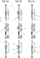
- FIGS. 1A, 1B, and 1C show a drive rod lock 1 that can be mounted on a door leaf in different functional positions, which has on the one hand a central center lock 2 and on the other hand two additional locks 3, 4, namely an upper additional lock 3 and a lower additional lock 4, which are coupled to the center lock 2 via drive rods 5, 6, namely an upper drive rod 5 and a lower drive rod 6.
- the center lock 2 and the additional locks 3, 4 are attached to the back of a lock face plate 7, which in turn is mounted on the door leaf.
- At least one locking strip is attached to a door frame (not shown), which has openings or apertures in which the locking elements of the espagnolette lock 1 engage during locking.
- the center lock 2 has a center housing 8 fastened to the lock face 7 and a locking element 9 which is adjustable in the center housing 8 and is referred to as the center bolt 9.
- the two additional locks 3, 4 each have an additional housing 10 fastened to the lock face 7 and one or more additional bolts 11, 12 each.
- the figures show an embodiment in which each additional lock has two locking elements, namely a latch bolt 11 on the one hand and a swivel hook bolt 12 on the other.
- each of the additional locks 3, 4 has a release mechanism 13, via which the additional bolts 11, 12 of the additional locks 3, 4 are automatically transferred to the extended locking position when the door leaf moves into the closed position.
- the release is implemented as a magnetic release. For this purpose, in the area of the door frame, e.g.
- the locking of the lock 1 always takes place automatically, without the need for manual or electric motor activation by a user.
- the lock and the door can be unlocked and opened by operating a handle from the outside or the inside of the door.
- a lock nut 15 that can be operated from both the outside and the inside of the door is provided in the center lock 2. provided, into which an actuating pin (not shown) for a handle or a panic bar is/will be inserted on both sides.
- a drive rod lock 1 with a panic function is shown, which is provided with a multi-part or split lock nut 15, which on the one hand has an outer nut 15a assigned to the outside of the door and on the other hand an inner nut 15b assigned to the inside of the door.
- the inner nut 15b is a panic nut and is permanently coupled to the lock mechanism for retracting the bolts 9, 11, 12.
- the outer nut 15a is not permanently coupled to the lock mechanism, but in the embodiment shown it is coupled via a remotely activated coupling element 16 in order to enable the door to be opened from the outside. This will also be discussed below.
- the espagnolette lock is always completely unlocked, ie all locking elements 9, 11, 12 are completely retracted (into the respective lock housing 8, 10 or behind the face plate 7) to enable the door to be opened.
- the structure and function of the additional locking devices 3, 4 are generally known. For example, they can be additional locking devices according to EP 3 372 757 B1
- the additional locking mechanism 3, 4 has at least one locking element, which is particularly preferably a latch bolt 11.
- the already mentioned swivel hook bolt 12 is provided in the illustrated embodiment.
- a lock chain 17 which can be moved in the longitudinal direction L of the lock is provided in the additional housing 10, which is referred to as an additional lock chain 17 and which is connected to the respective drive rod 5, 6 and with which the additional bolt or bolts can be moved when the drive rod 5, 6 is moved in the unlocking direction (e.g. upwards) from the extended locking position ( Fig 1B ) into the retracted opening position ( Fig. 1C ) is retractable.
- the additional lock chain 17 is held in the unlocking position by a locking element 18 and the locking element 18 can be actuated for automatic locking by a release magnet 14 arranged in or on the door frame or the locking strip in such a way that the locking element 18 releases the additional lock chain 17 so that the additional bolt 11, 12 is automatically transferred to the extended locking position.
- the latch bolt 11 can also be released from the extended locking position ( Fig. 1B ) or from a partially extended unlocking position ( Fig. 1A ) into a retracted opening position ( Fig. 1C ) retractable. This shows Fig.
- the partially extended unlocking position which can also be referred to as the basic position, in which the spring-loaded latch bolt 11 of the additional locking device protrudes a predetermined amount from the lock housing 10 and over the face plate 7.
- the latch bolt 11 is pushed back into the lock housing 10 against the force of the spring.
- the automatic release takes place via the magnetic release, so that the latch bolt 11 reaches the fully extended locking position, which in Fig. 1B is shown.
- the swivel hook latch 12 is extended. This mechanism, which will be discussed in more detail below, is basically known.
- the central latch 9 is designed according to the invention as a central latch bolt 9, which - like the latch bolts 11 of the additional locking devices 3, 4 - has a bevelled actuating edge and is loaded with a latch spring in the direction of an extended locking position and which can be moved between the extended locking position and a partially extended unlocked position and a retracted opening position (see Figures 1A, 1B and 1C ). It is now of particular importance that the locking of the central lock 2 is also implemented via the additional locking mechanism, namely in the embodiment via the lower additional locking mechanism 4.
- the central latch bolt 9 is coupled to the release mechanism 13 of the (lower) additional locking mechanism 4 in such a way that when released, not only the additional locking mechanism 11, 12 or the several additional locking mechanisms, but also the central latch bolt 9 is automatically extended into the locking position, which in Fig. 1B is shown.
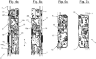
- the Figures 4A and 5A show the center lock 2 in the partially extended unlocking position and consequently in the basic position from two different views.
- the Figures 6A and 7A show the additional locking mechanism 3, 4, e.g. the lower additional locking mechanism 4, in the same functional position as the Fig. 1A corresponds.
- the center lock 2 has a center lock chain 19 that can be moved in the center housing 8 in the lock's longitudinal direction L, which in practice is also referred to as a drive rod connection slider and which is connected to or interacts with the drive rods 5, 6.
- the center lock chain is moved, for example, by operating the handle, so that not only the center bolt 9 but also the additional locking elements 11, 12 are retracted.
- This retracted functional position, in which the door can be opened, is in the Figures 4C and 5C or 6C and 7C, which are the Fig. 1C are equivalent to.
- both the additional locking devices 3, 4 and the center lock 2 then reach the Figures 4B and 5B and 6B and 7B.
- the automatic locking of the center lock 2 by triggering one of the additional locking devices, e.g. via the lower additional locking device 4.
- the center lock chain 19 is also moved via the (lower) drive rod 6 and thus the center latch bolt 9 is automatically or automatically moved into the position in Figures 4B and 5B shown locking position.
- the central lock chain 19 is forcibly coupled to the (lower) additional lock chain 17 in both directions via the drive rod 6.
- the lock chain 19 is therefore rigidly connected to the lower drive rod 6. This is e.g. in Fig. 4A shown.
- the connection can be implemented, for example, in such a way that a projection 19a of the center lock chain 19 engages in a corresponding recess at the upper end of the lower drive rod 6.
- no forced coupling in both directions is implemented between the center lock chain 19 and the upper drive rod 5. This is because the upper drive rod 5 only interacts with the center lock chain 19 in one direction, namely when unlocking, when the center lock chain 19 is moved upwards.
- the upper drive rod 5 rests with its lower end loosely on the center lock chain 19 or on the safety slide 21 also provided in the exemplary embodiment, with the safety slide 21 in turn resting loosely on the upper end of the center lock chain 19.
- the center lock chain 19 also works on the upper drive rod 5.
- the self-locking of the upper additional lock 3 does not affect the locking of the center lock.
- the automatic locking of the center lock 2 is - as explained - implemented in the embodiment via the lower additional lock 4. In the same way, an arrangement would also be possible in which the center lock is triggered via the upper additional lock.
- the coupling of the center lock chain 17 with the center bolt 9 is carried out via a rotatable, central driver 20, which acts on the bolt 9 via a pivoting latch lever 21. If the door leaf - as in Fig. 1B shown - into the closed position and thus into the area of the release magnets in the door frame, the locking elements 18 provided in the additional locking devices 3, 4, e.g. locking pins, are actuated in such a way that they release the lock chain 17, which then comes out of the Figures 6A, 7A shown basic position into the one in Figures 6B, 7B shown locking position. This automatically extends the additional latch bolt 11 and the swivel bolt 12 and at the same time secures them against back pressure.
- a rotatable, central driver 20 acts on the bolt 9 via a pivoting latch lever 21.
- a second push-back safety device is implemented via a spring-loaded safety slide 22, which, for example, with its safety projection 22', engages behind a locking edge 23 of the central latch bolt, e.g. its latch shaft, and thus secures the central latch bolt against being pushed back.
- a spring-loaded safety slide 22 which, for example, with its safety projection 22', engages behind a locking edge 23 of the central latch bolt, e.g. its latch shaft, and thus secures the central latch bolt against being pushed back.
- the latch lever 21 is pivoted with the central driver 20 during the unlocking process.
- the safety slide 22 is moved by the central lock chain 19 against the spring force.
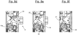
- FIG. 8A shows a section of the center lock 2 in the locking position with the latch bolt 9 fully extended. If the latch bolt 9 is pressed in, for example, during an attempted manipulation, the two push-back safeguards are activated.
- Fig. 8B It can be seen that the latch bolt 21 cannot be pushed in or can only be pushed in by a small amount of a few millimetres at most.
- Fig. 8C In this functional position the lock can be unlocked using the outer nut, for example. This removes the anti-return device.
- FIG. 8D shows a functional position in which the outer nut 15a is rotated by about 10° so that the center lock chain 19 is raised by about 2 mm. This deactivates the two latch bolt locks.
- the outer nut 15a can be rotated further so that according to Fig. 8E the chain 19 is raised by approximately 7 mm and the latch bolt 9 is retracted by approximately 14 mm.
- Fig. 8F shows the fully retracted functional position, in which the outer nut 15a is turned to the end stop and the chain 19 is raised by approximately 12 mm so that the latch bolt 9 is fully retracted by, for example, 20 mm.
- the lock Prerequisite for the lock to be able to move over the Fig. 8A to 8F
- the only way to unlock the outer nut 15a shown is by means of a corresponding electrical or remote activation. Because - as already mentioned - the inner nut 15b is permanently coupled to the lock mechanism as a panic lock for retracting the bolts. However, the outer nut 15a can be coupled and uncoupled with the lock mechanism via a remotely activated coupling element 16.
- the activatable coupling element 16 is designed in the embodiment as a pivoting coupling lever 16. The function of this Clutch lever 16 results from a comparative analysis of the Figures 8A and 8B on the one hand with the Fig. 8C on the other hand.
- FIGS. 8A and 8B show the clutch lever 16 in the disengaged (lower) functional position.
- Fig. 8C the clutch lever 16 is transferred to the engaged functional position. If the outer nut 15a in the functional position were to Fig. 8A rotated, this would not lead to a rotation of the latch lever 21 and thus to an unlocking. In the coupled position, however, the outer nut 15a is coupled via the upwardly pivoted coupling lever 16 to the central driver 20 and thus also to the latch lever 21.
- this coupling element 16 is carried out remotely via, for example, an electric motor, which can be referred to as a coupling motor 24 and which, for example, in Fig. 4B
- This clutch motor 24 operates on the Fig. 4B clutch lever 16 shown, whereby the Figures 4B and 5B show the clutch lever 16 in the disengaged position. In the functional position according to Figures 4B and 5B unlocking the lock would therefore only be possible via the inner handle 15b and not via the outer handle 15a.
- the clutch lever 16 can be pivoted via the clutch motor 24 and transferred into the effective range of the lock nut 15a, so that the outer lock nut 15a is coupled with the central driver 20, and in particular in Figures 8C to 8F is shown.
- espagnolette lock Of particular importance in the espagnolette lock according to the invention is the automatic release via one of the additional locks 3, 4, so that not only the additional locks, but also the center lock 2 is locked without a separate release mechanism being provided in the center lock.
- This enables a particularly compact design of the center lock.
- center locks with own release mechanism - installation space is created which can be used, for example, for the integration of the clutch function and in particular for the integration of the electric motor.
- the center lock is also shown in an exploded view in the Figures 2 and 3 so that the individual mechanical components are clearly visible. From the Figures 2 and 3 The structural design of the essential levers and in particular the structural design of the intermediate lever 20 and its interaction with the lock nut halves 15a and 15b are therefore clearly evident.
- the figures show an embodiment in which the secondary locking devices are each equipped with two locking elements 11, 12, namely a latch bolt 11 on the one hand and a swivel hook bolt 12 on the other.
- This embodiment is also shown in the EP 3 372 757 B1 described.
- an additional locking system with only one locking element e.g. only one Use latch bolt 11, as shown in the DE 10 2008 011 551 A1 described.
- secondary locks can be used that are not equipped with a magnetic but rather a mechanical release. It is important, however, that the center lock itself is not equipped with its own release mechanism, but that the locking of the center lock is always triggered via one of the additional locks.
- FIGS. 1A, 1B and 1C show a preferred embodiment of a drive rod lock 1 according to the invention, which has several additional locks 3, 4, namely an upper additional lock 3 and a lower additional lock 4. As described, the automatic or self-acting locking of the center lock 2 takes place via only one, namely the lower additional lock 4.
- Fig. 9 a modified, second embodiment of a drive rod lock 1 according to the invention, which has only one (single) additional locking mechanism 4, which in this embodiment is arranged below the center lock 2.
- the center lock 2 and the lower additional locking mechanism 4 can be designed in the same way in this embodiment as in the embodiment according to Figures 1A, 1B and 1C .
- the explanations regarding the structure and functioning and the interaction of the central lock 2 and the lower additional locking mechanism 4 therefore apply equally to the embodiment according to Fig. 9 .
- Fig. 9 the espagnolette lock 1 in the locked functional position accordingly Fig. 1B .
- Another interesting feature of the illustrated designs is the fact that the external lock nut can be activated and deactivated via remote control, so that, for example, the access options to a door in the property area can be varied remotely. Panic release is always possible using the inside handle.
- the invention can also be implemented with a lock with a one-piece lock nut, which can also be provided with the described coupling lever without a panic function, via which the one-piece lock nut can then be temporarily coupled to and uncoupled from the lock mechanism.
- the clutch motor There are various options for supplying power to the clutch motor and for transmitting signals, e.g. from the door frame side to the lock case via cable connections or tappet contacts.
- designs without wiring can also be implemented, in which the power is supplied via an inductive interface.
- the transmitter unit can be installed in the locking strip on the frame side and the receiver unit can be integrated into the center lock case.
- the basically known "working current” and “quiescent current” variants can be implemented in the system according to the invention. In the working current variant, a signal is present permanently or for a desired period of time, so that the nut halves are coupled or the one-piece nut is coupled and the door can be opened from the outside.
- the quitting current variant can be set during installation, in which the lock is permanently powered, but in this case the outside handle is disengaged so that access is not possible.
- the outside handle is engaged.
- a latch bolt in the center lock, which has already been highlighted, and preferably without any other locking elements in the center lock. In its basic position, this latch bolt is not completely retracted like a bolt, but rather it deliberately protrudes a predetermined amount beyond the faceplate. A mechanism for the usual locking of a classic bolt can be dispensed with. In addition, a latch bolt enables a better translation of the displacement of the lock chain in the longitudinal direction into the perpendicular movement of the latch bolt.
Landscapes
- Engineering & Computer Science (AREA)
- Mechanical Engineering (AREA)
- Business, Economics & Management (AREA)
- Emergency Management (AREA)
- Structural Engineering (AREA)
- Lock And Its Accessories (AREA)
Applications Claiming Priority (1)
| Application Number | Priority Date | Filing Date | Title |
|---|---|---|---|
| DE102023122178.7A DE102023122178A1 (de) | 2023-08-18 | 2023-08-18 | Automatisch verriegelndes Treibstangenschloss |
Publications (1)
| Publication Number | Publication Date |
|---|---|
| EP4509683A1 true EP4509683A1 (fr) | 2025-02-19 |
Family
ID=91923680
Family Applications (1)
| Application Number | Title | Priority Date | Filing Date |
|---|---|---|---|
| EP24188055.8A Pending EP4509683A1 (fr) | 2023-08-18 | 2024-07-11 | Crémone-serrure à verrouillage automatique |
Country Status (2)
| Country | Link |
|---|---|
| EP (1) | EP4509683A1 (fr) |
| DE (1) | DE102023122178A1 (fr) |
Citations (4)
| Publication number | Priority date | Publication date | Assignee | Title |
|---|---|---|---|---|
| EP1158126A1 (fr) * | 1999-09-25 | 2001-11-28 | KARL FLIETHER GmbH & Co. | Serrure |
| DE102008011551A1 (de) | 2008-02-28 | 2009-09-10 | Carl Fuhr Gmbh & Co. Kg | Selbstverriegelnde Zusatzverriegelung |
| DE202009016137U1 (de) * | 2009-11-30 | 2010-04-08 | Carl Fuhr Gmbh & Co. Kg | Treibstangenschloss mit Panikfunktion und Mehrfachverriegelung |
| EP3372757B1 (fr) | 2017-03-10 | 2021-04-28 | Carl Fuhr GmbH & Co. KG | Unité de verrouillage pour une installation de verrouillage d'une porte |
Family Cites Families (2)
| Publication number | Priority date | Publication date | Assignee | Title |
|---|---|---|---|---|
| DE9407664U1 (de) * | 1994-05-09 | 1995-09-07 | Bks Gmbh, 42549 Velbert | Einsteckschloß mit Fallenriegel und Schloßriegel |
| AT513470B1 (de) * | 2012-10-03 | 2015-01-15 | Roto Frank Ag | Türschloss |
-
2023
- 2023-08-18 DE DE102023122178.7A patent/DE102023122178A1/de active Pending
-
2024
- 2024-07-11 EP EP24188055.8A patent/EP4509683A1/fr active Pending
Patent Citations (4)
| Publication number | Priority date | Publication date | Assignee | Title |
|---|---|---|---|---|
| EP1158126A1 (fr) * | 1999-09-25 | 2001-11-28 | KARL FLIETHER GmbH & Co. | Serrure |
| DE102008011551A1 (de) | 2008-02-28 | 2009-09-10 | Carl Fuhr Gmbh & Co. Kg | Selbstverriegelnde Zusatzverriegelung |
| DE202009016137U1 (de) * | 2009-11-30 | 2010-04-08 | Carl Fuhr Gmbh & Co. Kg | Treibstangenschloss mit Panikfunktion und Mehrfachverriegelung |
| EP3372757B1 (fr) | 2017-03-10 | 2021-04-28 | Carl Fuhr GmbH & Co. KG | Unité de verrouillage pour une installation de verrouillage d'une porte |
Also Published As
| Publication number | Publication date |
|---|---|
| DE102023122178A1 (de) | 2025-02-20 |
Similar Documents
| Publication | Publication Date | Title |
|---|---|---|
| DE102006011263B4 (de) | Verriegelungssystem für eine Tür | |
| EP1932989B1 (fr) | Système de fermeture pour portes, fenêtres ou analogues, en particulier crémone-serrure à fonction d'urgence et de verrouillage à plusieurs points | |
| EP3832055B1 (fr) | Unité de verrouillage pour une installation de verrouillage d'une porte | |
| EP0942135B2 (fr) | Dispositif de verrouillage | |
| EP1936075A2 (fr) | Serrure anti-panique électromécanique à verrouillage automatique | |
| DE19730552C1 (de) | Einrichtung zum Entriegeln eines mechanisch selbstverriegelnden Mehrfachschlosses | |
| EP2339096B1 (fr) | Serrure à crémone dotée d'une fonction anti-panique et d'un verrouillage multiple | |
| EP3070238B1 (fr) | Dispositif de verrouillage pour une porte ou une fenêtre | |
| DE10122466C2 (de) | Schloß | |
| EP3045624A1 (fr) | Dispositif de verrouillage d'un battant pivotant | |
| DE29619007U1 (de) | Verriegelungsvorrichtung | |
| EP3628801B1 (fr) | Dispositif de fermeture pour une porte et procédé pour ouvrir une porte | |
| EP3907357B1 (fr) | Dispositif de verrouillage | |
| EP3543436B1 (fr) | Contre-serrure pour vantail passif | |
| AT9709U1 (de) | Türschloss | |
| EP1936073A2 (fr) | Serrure anti-panique à verrouillage automatique | |
| EP4509683A1 (fr) | Crémone-serrure à verrouillage automatique | |
| EP3655601B1 (fr) | Serrure | |
| EP3543437B1 (fr) | Dispositif formant serrure pourvu d'une serrure pour une porte à battants mobiles | |
| DE102020205673B3 (de) | Selbstverriegelndes Schloss | |
| EP1936076B1 (fr) | Serrure anti-panique à verrouillage automatique | |
| DE102005001312A1 (de) | Fernbetätigter Türöffner | |
| DE10337593B4 (de) | Tor, insbesondere für Garagen | |
| DE102004040692A1 (de) | Paniktürverschluss | |
| DE102024107462A1 (de) | Treibriegelschloss variabel einsetzbar |
Legal Events
| Date | Code | Title | Description |
|---|---|---|---|
| PUAI | Public reference made under article 153(3) epc to a published international application that has entered the european phase |
Free format text: ORIGINAL CODE: 0009012 |
|
| STAA | Information on the status of an ep patent application or granted ep patent |
Free format text: STATUS: THE APPLICATION HAS BEEN PUBLISHED |
|
| STAA | Information on the status of an ep patent application or granted ep patent |
Free format text: STATUS: REQUEST FOR EXAMINATION WAS MADE |
|
| AK | Designated contracting states |
Kind code of ref document: A1 Designated state(s): AL AT BE BG CH CY CZ DE DK EE ES FI FR GB GR HR HU IE IS IT LI LT LU LV MC ME MK MT NL NO PL PT RO RS SE SI SK SM TR |
|
| 17P | Request for examination filed |
Effective date: 20250130 |