EP4509715A2 - Gerotorpumpe und motor-pumpen-einheit - Google Patents
Gerotorpumpe und motor-pumpen-einheit Download PDFInfo
- Publication number
- EP4509715A2 EP4509715A2 EP24191639.4A EP24191639A EP4509715A2 EP 4509715 A2 EP4509715 A2 EP 4509715A2 EP 24191639 A EP24191639 A EP 24191639A EP 4509715 A2 EP4509715 A2 EP 4509715A2
- Authority
- EP
- European Patent Office
- Prior art keywords
- housing
- outer rotor
- pump
- rotor
- pressure
- Prior art date
- Legal status (The legal status is an assumption and is not a legal conclusion. Google has not performed a legal analysis and makes no representation as to the accuracy of the status listed.)
- Pending
Links
Images




Classifications
-
- F—MECHANICAL ENGINEERING; LIGHTING; HEATING; WEAPONS; BLASTING
- F04—POSITIVE - DISPLACEMENT MACHINES FOR LIQUIDS; PUMPS FOR LIQUIDS OR ELASTIC FLUIDS
- F04C—ROTARY-PISTON, OR OSCILLATING-PISTON, POSITIVE-DISPLACEMENT MACHINES FOR LIQUIDS; ROTARY-PISTON, OR OSCILLATING-PISTON, POSITIVE-DISPLACEMENT PUMPS
- F04C2/00—Rotary-piston machines or pumps
- F04C2/08—Rotary-piston machines or pumps of intermeshing-engagement type, i.e. with engagement of co-operating members similar to that of toothed gearing
- F04C2/10—Rotary-piston machines or pumps of intermeshing-engagement type, i.e. with engagement of co-operating members similar to that of toothed gearing of internal-axis type with the outer member having more teeth or tooth-equivalents, e.g. rollers, than the inner member
- F04C2/102—Rotary-piston machines or pumps of intermeshing-engagement type, i.e. with engagement of co-operating members similar to that of toothed gearing of internal-axis type with the outer member having more teeth or tooth-equivalents, e.g. rollers, than the inner member the two members rotating simultaneously around their respective axes
-
- F—MECHANICAL ENGINEERING; LIGHTING; HEATING; WEAPONS; BLASTING
- F04—POSITIVE - DISPLACEMENT MACHINES FOR LIQUIDS; PUMPS FOR LIQUIDS OR ELASTIC FLUIDS
- F04C—ROTARY-PISTON, OR OSCILLATING-PISTON, POSITIVE-DISPLACEMENT MACHINES FOR LIQUIDS; ROTARY-PISTON, OR OSCILLATING-PISTON, POSITIVE-DISPLACEMENT PUMPS
- F04C11/00—Combinations of two or more machines or pumps, each being of rotary-piston or oscillating-piston type; Pumping installations
- F04C11/005—Combinations of two or more machines or pumps, each being of rotary-piston or oscillating-piston type; Pumping installations of dissimilar working principle
-
- F—MECHANICAL ENGINEERING; LIGHTING; HEATING; WEAPONS; BLASTING
- F04—POSITIVE - DISPLACEMENT MACHINES FOR LIQUIDS; PUMPS FOR LIQUIDS OR ELASTIC FLUIDS
- F04C—ROTARY-PISTON, OR OSCILLATING-PISTON, POSITIVE-DISPLACEMENT MACHINES FOR LIQUIDS; ROTARY-PISTON, OR OSCILLATING-PISTON, POSITIVE-DISPLACEMENT PUMPS
- F04C2/00—Rotary-piston machines or pumps
- F04C2/30—Rotary-piston machines or pumps having the characteristics covered by two or more groups F04C2/02, F04C2/08, F04C2/22, F04C2/24 or having the characteristics covered by one of these groups together with some other type of movement between co-operating members
- F04C2/34—Rotary-piston machines or pumps having the characteristics covered by two or more groups F04C2/02, F04C2/08, F04C2/22, F04C2/24 or having the characteristics covered by one of these groups together with some other type of movement between co-operating members having the movement defined in groups F04C2/08 or F04C2/22 and relative reciprocation between the co-operating members
- F04C2/344—Rotary-piston machines or pumps having the characteristics covered by two or more groups F04C2/02, F04C2/08, F04C2/22, F04C2/24 or having the characteristics covered by one of these groups together with some other type of movement between co-operating members having the movement defined in groups F04C2/08 or F04C2/22 and relative reciprocation between the co-operating members with vanes reciprocating with respect to the inner member
- F04C2/3441—Rotary-piston machines or pumps having the characteristics covered by two or more groups F04C2/02, F04C2/08, F04C2/22, F04C2/24 or having the characteristics covered by one of these groups together with some other type of movement between co-operating members having the movement defined in groups F04C2/08 or F04C2/22 and relative reciprocation between the co-operating members with vanes reciprocating with respect to the inner member the inner and outer member being in contact along one line or continuous surface substantially parallel to the axis of rotation
- F04C2/3442—Rotary-piston machines or pumps having the characteristics covered by two or more groups F04C2/02, F04C2/08, F04C2/22, F04C2/24 or having the characteristics covered by one of these groups together with some other type of movement between co-operating members having the movement defined in groups F04C2/08 or F04C2/22 and relative reciprocation between the co-operating members with vanes reciprocating with respect to the inner member the inner and outer member being in contact along one line or continuous surface substantially parallel to the axis of rotation the surfaces of the inner and outer member, forming the working space, being surfaces of revolution
-
- F—MECHANICAL ENGINEERING; LIGHTING; HEATING; WEAPONS; BLASTING
- F04—POSITIVE - DISPLACEMENT MACHINES FOR LIQUIDS; PUMPS FOR LIQUIDS OR ELASTIC FLUIDS
- F04C—ROTARY-PISTON, OR OSCILLATING-PISTON, POSITIVE-DISPLACEMENT MACHINES FOR LIQUIDS; ROTARY-PISTON, OR OSCILLATING-PISTON, POSITIVE-DISPLACEMENT PUMPS
- F04C2/00—Rotary-piston machines or pumps
- F04C2/30—Rotary-piston machines or pumps having the characteristics covered by two or more groups F04C2/02, F04C2/08, F04C2/22, F04C2/24 or having the characteristics covered by one of these groups together with some other type of movement between co-operating members
- F04C2/34—Rotary-piston machines or pumps having the characteristics covered by two or more groups F04C2/02, F04C2/08, F04C2/22, F04C2/24 or having the characteristics covered by one of these groups together with some other type of movement between co-operating members having the movement defined in groups F04C2/08 or F04C2/22 and relative reciprocation between the co-operating members
- F04C2/356—Rotary-piston machines or pumps having the characteristics covered by two or more groups F04C2/02, F04C2/08, F04C2/22, F04C2/24 or having the characteristics covered by one of these groups together with some other type of movement between co-operating members having the movement defined in groups F04C2/08 or F04C2/22 and relative reciprocation between the co-operating members with vanes reciprocating with respect to the outer member
- F04C2/3562—Rotary-piston machines or pumps having the characteristics covered by two or more groups F04C2/02, F04C2/08, F04C2/22, F04C2/24 or having the characteristics covered by one of these groups together with some other type of movement between co-operating members having the movement defined in groups F04C2/08 or F04C2/22 and relative reciprocation between the co-operating members with vanes reciprocating with respect to the outer member the inner and outer member being in contact along one line or continuous surface substantially parallel to the axis of rotation
- F04C2/3564—Rotary-piston machines or pumps having the characteristics covered by two or more groups F04C2/02, F04C2/08, F04C2/22, F04C2/24 or having the characteristics covered by one of these groups together with some other type of movement between co-operating members having the movement defined in groups F04C2/08 or F04C2/22 and relative reciprocation between the co-operating members with vanes reciprocating with respect to the outer member the inner and outer member being in contact along one line or continuous surface substantially parallel to the axis of rotation the surfaces of the inner and outer member, forming the working space, being surfaces of revolution
Definitions
- the invention relates to a gerotor pump for pumping a fluid and a motor-pump unit comprising the gerotor pump.
- gerotor pumps also known as “gear ring pumps” or “Eaton pumps” have a rotating outer rotor and a rotating inner rotor, with the inner rotor arranged radially inside the outer rotor.
- the inner rotor is usually driven by a motor.
- the inner rotor is designed as a gear and the outer rotor as a toothed ring, with the inner rotor and the outer rotor having different axes of rotation.
- the outer rotor runs eccentrically on an external toothing of the inner rotor. Due to the changing volumes between the tooth gaps between the inner rotor and the outer rotor, pressure areas are formed, also called pumping chambers, by means of which the fluid is pumped.
- the conventional gerotor pumps have the disadvantage that manufacturing tolerances lead to a so-called tooth tip clearance between the teeth of the inner rotor and the outer rotor. This creates a gap, particularly between opposing teeth of the inner rotor and the outer rotor. This tooth tip clearance is already present when the pump is at rest, i.e. even when the pump is not in operation. When the pump is in operation, the pressure increases and further increases the gap between the inner rotor and the outer rotor, causing an internal leak and reducing the efficiency of the pump.
- the gerotor pump is designed and suitable for conveying a fluid from an inlet pump chamber connected to an inlet to an outlet pump chamber of the gerotor pump connected to an outlet.
- the gerotor pump has a rotatable outer rotor and a rotatable inner rotor.
- the inner rotor is arranged radially inside the outer rotor.
- the inner rotor and the outer rotor have different axes of rotation.
- the gerotor pump also has a housing with a housing space in which the outer rotor and the inner rotor are accommodated.
- the gerotor pump also has a plurality of radially displaceable pressure elements.
- the pressure elements are arranged on an outer circumference of the outer rotor. When the gerotor pump is in operation, the pressure elements rest on the housing, so that pressure chambers are formed between the outer rotor and the housing and/or between the outer rotor and the pressure elements.
- the pressure chambers are fluidly connected to the inlet pump chamber and/or the outlet pump chamber.
- the pressure chambers are formed between the outer rotor and the housing and/or between the outer rotor and the pressure elements when the pump is in operation. These pressure chambers produce a force when the pump is in operation that presses or adjusts the outer rotor radially against the inner rotor. This effect is also known as "radial compensation”. This reduces the gap between the outer rotor and the inner rotor, particularly when pressures increase when the pump is in operation, thus increasing efficiency.
- the pressure chambers are advantageously defined as corresponding pressure areas of the fluid to be conveyed, which are separate or in addition to the pressure areas between the outer rotor and the inner rotor, through which the fluid is mainly conveyed.
- the pressure areas formed between the outer rotor and the inner rotor for the main fluid conveyance are also called “primary pressure areas” and the pressure chambers defined above for radial compensation, which are generated by the pressure elements, are also called “secondary pressure areas”.
- the gerotor pump has at least two pressure elements.
- the gerotor pump particularly preferably has at least three to seven, more preferably at least eight pressure elements.
- the gerotor pump particularly preferably has exactly eight pressure elements or exactly six pressure elements.
- the housing has a plurality of housing openings along its inner circumference, in each of which a pressure element is at least partially is arranged.
- the housing openings (hereinafter also referred to as “openings") are advantageously slots and/or holes.
- the pressure elements advantageously rest on the housing along a circumferential direction of the housing within the housing opening.
- the pressure elements rest on the outer circumference of the outer rotor or are positioned or pre-tensioned against the outer circumference of the outer rotor.
- the housing openings are advantageously fluidically connected to the inlet pump chamber and/or the outlet pump chamber. In other words, the fluid to be pumped reaches the openings.
- This has the advantage that the pressure elements are positioned against the outer rotor by hydraulic pressure in the openings when the gerotor pump is operating, thus forming the secondary pressure areas.
- the provision of the pressure elements in housing openings also has the advantage that adjustments to the inner rotor or the outer rotor are not absolutely necessary, which simplifies the manufacture of the gerotor pump.
- the gerotor pump advantageously has a plurality of spring elements, wherein the spring elements are each arranged in one of the housing openings.
- the spring elements pre-tension the respective pressure element (in the same housing opening) towards the outer rotor. In other words, the spring element presses the pressure element against the outer rotor.
- the spring elements are advantageously coil springs or leaf springs, whereby different types of spring elements can be arranged in different housing openings. Furthermore, several spring elements can be arranged in one housing opening. For example, two coil springs can be arranged in one housing opening. Alternatively or in other housing openings, a (single) leaf spring can be arranged in the housing opening.
- the outer rotor has a plurality of openings along its outer circumference, in each of which a pressure element is at least partially arranged.
- the openings are advantageously slots and/or bores.
- the openings are each fluidically connected to the inlet pump chamber and/or to the outlet pump chamber. In other words, the fluid to be pumped reaches the openings.
- the pressure elements are radially displaceable and advantageously arranged at least partially in the aforementioned openings/housing openings.
- the pressure elements can, for example, be completely within the respective opening when the pump is at rest. and, when the pump is operating, are displaced radially outwards by an acting centrifugal force in order to be only partially arranged in the respective opening.
- the pressure elements can all emerge from their respective opening by the same or a similar amount, or they can emerge from their respective opening by different amounts.
- the pressure elements can, for example, be arranged completely within the respective opening when the pump is at rest.
- a hydraulic pressure of the inlet pump chamber and/or the outlet pump chamber, which are fluidly connected to the opening can position the respective pressure element against the outer rotor.
- the pressure elements can be positioned or preloaded against the outer rotor by means of the spring elements even when the pump is at rest.
- the housing has a housing cover and a housing base, between which (along the axial direction) the inner rotor and the outer rotor are arranged.
- gaps are provided between the housing cover and the inner rotor and the outer rotor and between the housing base and the inner rotor and the outer rotor, which form parts of the inlet pump chamber and the outlet pump chamber, so that the fluid to be pumped axially surrounds the inner rotor and the outer rotor.
- the housing cover and/or the housing base advantageously have grooves which, together with gaps between the inner rotor and the outer rotor, form the inlet pump chamber and the outlet pump chamber.
- the grooves advantageously run at least partially along a circumferential direction of the outer rotor.
- the grooves are each arranged on two sides in the circumferential direction of the inlet and/or the outlet and extend along the circumferential direction away from the inlet and/or the outlet.
- the grooves advantageously increase a volume of the inlet pump chamber and/or outlet pump chamber between the housing cover/housing base and the outer rotor and/or inner rotor, thereby reducing viscous friction with the fluid and thus reducing surfaces with necessarily low play/tolerances, thereby increasing the efficiency of the pump.
- the pressure elements are each rotary valves.
- the pressure elements designed as rotary valves are preferably essentially rectangular and plate-shaped.
- the rotary valves advantageously have rounded corners.
- At least one housing-side side surface of the rotary valves arranged in openings of the outer rotor, in particular the housing-side side surface which comes into contact with the housing, is rounded. This reduces friction between the rotary valve and the housing. It is also advantageous if at least one outer rotor-side side surface of the rotary valves arranged in openings of the housing, in particular the outer rotor-side side surface which comes into contact with the outer rotor, is rounded. This reduces friction between the rotary valve and the outer rotor.
- a height of the rotary valves along an axial direction of the outer rotor is less than a height of the outer rotor or less than a height of the housing in the axial direction.
- a depth in the axial direction of the opening or the slot or the bore in the outer rotor or in the housing is advantageously greater than a height of the respective rotary valve.
- the rotary valves By adjusting the height of the rotary valves, an amount of fluid flowing on the rotary valve as described above can be controlled, so that a pressure between the pressure chambers generated by the rotary valves can be controlled.
- the rotary valves have different heights, or all have the same height.
- a height of the rotary vanes is 90%, preferably 95%, even more preferably 98%, of the height of the outer rotor or the height of the housing.
- a difference in heights between the outer rotor or the housing and the rotary vanes is more than (only) due to manufacturing tolerances. This allows a particularly good effect of the rotary vanes and a reduction in friction.
- the height of the rotary vanes can be about 50% of the height of the outer rotor or the height of the housing.
- the aforementioned height is to be understood in particular as the (axial) length of the aforementioned housing-side side surface or the aforementioned outer rotor-side side surface.
- the rotary valves separate the housing space along a circumferential direction of the outer rotor at least in sections.
- pressure chambers are formed at least between the rotary valves along the circumferential direction. These pressure chambers are preferably formed in addition to the primary pressure areas explained above (between the inner rotor and the outer rotor). These pressure chambers are advantageously formed along the circumferential direction between the rotary valves and in Radial direction between the outer rotor and the housing.
- the fluid pressures in the pressure chambers are advantageously not axisymmetric with respect to the axial direction or with respect to the axes of rotation of the outer rotor and/or the inner rotor.
- the pressure that arises within the pressure chambers is different between at least some of the pressure chambers. This advantageously creates a force that pushes the outer rotor against the inner rotor, so that the gap between them is reduced and the efficiency is thereby increased.
- the pressure elements are each piston.
- the respective opening is advantageously designed as a bore in which the respective piston is arranged so as to be radially displaceable.
- the opening is fluidically connected to the inlet pump chamber and/or the outlet pump chamber.
- each opening in the outer rotor in which such a piston is arranged has a radially inner end (inner rotor-side) and a radially outer (housing-side) end, wherein the piston protrudes displaceably at least partially from the housing-side end.
- a radial inner side of the opening in the outer rotor which is an inner side of the opening at its radially inner end and which is fluidically connected to the inlet pump chamber and/or to the outlet pump chamber, forms a piston pressure chamber with the piston.
- the piston is arranged in an opening in the housing
- the radially inner end of the opening is arranged on the outer rotor side and the radially outer end of the opening is arranged radially further out in the housing.
- the piston pressure chamber is formed between the radially outer end of the housing opening and the piston, which is arranged between the housing and the outer rotor.
- the piston and the opening together form a piston-cylinder arrangement.
- the piston pressure chamber advantageously exerts the above-mentioned actuating force on the outer rotor, so that the efficiency of the pump is increased.
- the radially inner end of the opening in the outer rotor or the radially outer end of the housing opening is preferably connected to the gap between the outer rotor and the housing cover or, depending on the axial orientation of the opening, to the gap between the outer rotor and the housing base, so that the fluid in this gap can flow into the opening.
- the design of the pressure elements as rotary valves and as pistons can be combined.
- at least one pressure element is designed as a rotary valve and at least one pressure element as a piston.
- a pressure element can be functionally designed as a rotary valve and as a piston at the same time, for example by designing the rotary valve as a piston with an exemplary height in the axial direction of at least 50% or 90%, or one of the other values mentioned above for the rotary valves, of the height of the outer rotor.
- Such pistons advantageously separate the housing space along the circumferential direction of the outer rotor at least in sections and form additional pressure chambers along the circumferential direction between the outer rotor and the housing in addition to the piston pressure chambers.
- the outer rotor and the housing space have different center axes perpendicular to the radial direction.
- the center axis of the housing space and the axis of rotation of the outer rotor do not match.
- the outer rotor is not arranged centrally in the housing space.
- an angular or circumferential position of a maximum pressure generated in the secondary pressure chambers is changed accordingly when the pump is operating, so that a resulting pressure force from all secondary pressure chambers counteracts the resulting pressure force of the primary pressure chambers, which turns the outer rotor. If the pressure force from the primary pressure chambers is more than compensated (more than completely counteracted), the gap between the outer rotor and inner rotor is reduced, which can further increase the efficiency.
- the outer rotor has at least one, in particular a plurality of outer rotor groove(s) distributed along the circumferential direction.
- the outer rotor grooves are in particular each formed along the circumferential direction between the aforementioned openings.
- the Outer rotor grooves advantageously reduce viscous friction with the fluid between the outer rotor and the housing cover and/or housing base.
- the outer rotor grooves can be formed on one or both axial sides of the outer rotor (housing base side and/or housing cover side).
- the outer rotor grooves are formed in particular as recesses in the outer rotor that are elongated along the circumferential direction and deep in the axial direction.
- the inner rotor can preferably also have such corresponding grooves (inner rotor grooves).
- the housing preferably has at least one, in particular a plurality of housing groove(s) distributed along the circumferential direction.
- the housing grooves are in particular each formed along the circumferential direction between the aforementioned housing openings.
- the housing grooves advantageously reduce viscous friction with the fluid between the housing and the housing cover and/or housing base.
- the housing grooves can be formed on one or both axial sides of the housing (on the housing base side and/or the housing cover side).
- the housing grooves are in particular formed as recesses in the housing that are elongated along the circumferential direction and deep in the axial direction.
- the inner rotor and/or the outer rotor can preferably have such grooves.
- the gerotor pump also has at least one compensation plate, which is/are arranged in the axial direction between the housing cover and/or housing base and the inner rotor and/or outer rotor and enables axial compensation of the gerotor pump.
- the gerotor pump advantageously has radial compensation and axial compensation, which makes the efficiency particularly high.
- the invention also relates to a motor-pump unit.
- the motor-pump unit has a gerotor pump according to one of the above preferred embodiments. Furthermore, the motor-pump unit has a motor which is connected to the inner rotor and is designed to rotate the inner rotor to operate the gerotor pump. The motor is mechanically connected to the inner rotor in particular by means of a shaft.
- the motor-pump unit has an increased efficiency.
- the gerotor pump and the motor-pump unit also have the following advantages.
- the components can be manufactured at significantly reduced costs, as manufacturing tolerances can be significantly expanded. Due to the higher efficiency, they can be used in higher pressure ranges.
- the radial compensation increases performance stability over different pressures. Furthermore, no further control is required for the radial compensation explained above. necessary because the radial compensation functions self-controllingly through a hydraulic operating principle.
- Fig. 1 shows a schematic cross-sectional view of a gerotor pump 1 according to a first embodiment of the present invention.
- the gerotor pump 1 (hereinafter "pump 1") for conveying a fluid has a rotatable inner rotor 7 and a rotatable outer rotor 6.
- the inner rotor 7 is designed as a gear wheel.
- the outer rotor 6 is designed as a toothed ring.
- the inner rotor 7 and the outer rotor 6 are accommodated in a housing space 11 of a housing 10.
- the inner rotor 7 is arranged along a radial direction 15 within the outer rotor 6.
- the inner rotor 7 is rotatable about an inner rotor rotation axis 8, while the outer rotor 6 is rotatable about an outer rotor rotation axis 9.
- the axes of rotation 8, 9 are different from each other, i.e. arranged parallel to each other.
- a rotation of the inner rotor 7 causes a rotation of the outer rotor 6. The operation of the pump 1 is described below with reference to Fig. 2 explained.
- the outer rotor 6 is not arranged centrally in the housing space 11, at least when the pump 1 is at rest.
- the center axes of the housing space 11 and the outer rotor 6 are different from one another.
- the inner rotor 7 is arranged centrally in the housing space 11, so that a center axis of the housing space 11 coincides with the inner rotor rotation axis 8.
- the center axis of the outer rotor 6 coincides with the outer rotor rotation axis 9.
- the outer rotor 6 has at least two, here eight, openings 16 on its outer circumference 13.
- the openings 16 are, as described below with reference to Fig. 3 & 4 explained, in this case slots.
- the openings 16 are preferably evenly distributed over the outer circumference 13 of the outer rotor 6, i.e. arranged symmetrically.
- the openings 16 can be arranged asymmetrically along the outer circumference 13, so that different distances are formed between at least two pairs of openings 16 along the outer circumference 13.
- a rotary slide valve 12 is arranged in each opening as a pressure element.
- the rotary slide valves 12 can be moved radially within the respective openings 16.
- a centrifugal force resulting from the rotation causes the rotary slide valves 12 to protrude from the respective openings 12 and rest against the housing 10.
- the fluid to be pumped is also partially located in the housing space 11 between the outer rotor 6 and the inner rotor 7.
- the rotary vanes 12 form pressure chambers 14.
- the pressure chambers 14 are formed in the radial direction 15 between the outer rotor 7 and the housing 10 and along a circumferential direction 18 between the rotary vanes 12.
- the fluid is located partially within the respective opening 16 radially further inward than the respective rotary valve 12.
- the fluid is located in an opening space 24 between a radial inner side 17 of the opening 16 and the rotary valve 12, so that opening space pressure chambers 25 are formed.
- the opening space pressure chambers 25 provide a spring for the rotary valve 12 and, as explained below with reference to embodiment two, a (further) setting force for the outer rotor 6.
- a spring element can be arranged in the respective opening space 24, which springs the rotary valve 12 or radially preloads/sets it.
- Fig. 2 shows a schematic plan view of the gerotor pump 1 according to the first embodiment of the present invention.
- the Fig. 2 in particular a housing cover 20, which covers the outer rotor 6, the inner rotor 7 and the housing space 11.
- the components covered by the housing cover 20 are indicated by dashed lines.
- the rotary valves 12 are shown in the Fig. 2 not shown.
- the pump 1 has a housing cover 20 and a housing base 21, wherein the housing base 21 is not (directly) visible in the present view.
- the inner rotor 7 and the outer rotor 6 are arranged between the housing cover 20 and the housing base 21 along an axial direction 30 of the outer rotor 6, which coincides with the outer rotor rotation axis 9 (in the present case in the z direction).
- a distance (axial gap) is formed between at least the housing cover 20 (and/or at least the housing base 21) and the outer rotor 6 and the inner rotor 7 along the axial direction 30, so that fluid surrounds the outer rotor 6 and the inner rotor 7.
- Openings for an inlet 2 and an outlet 4 are formed in the housing base 21.
- the fluid is pumped by the pump 1 from the inlet 2 to the outlet 4.
- the housing cover 20 has grooves 22 which extend along the circumferential direction 18 and are each connected to the inlet 2 or the outlet 4.
- the inlet pump chamber 3 and the outlet pump chamber 5 of the pump 1 also comprise the aforementioned fluid or fluid volume in the axial direction 30 between the housing cover 20 and/or housing base 21 and the outer rotor 6 and the inner rotor 7.
- fluid is conveyed from the inlet 2 to the outlet 4 along the circumferential direction 18.
- the volumes 23 of the gaps initially become larger starting from the inlet 2 along the circumferential direction 18 (clockwise in this case), so that fluid is sucked in from the inlet 2.
- the volumes 23 initially remain almost constant before the volumes 23 then become smaller.
- the fluid is subjected to pressure and the fluid is conveyed out of the outlet 4.
- the resulting pressure ranges of the fluid by means of which the fluid is mainly conveyed between the inlet 2 and the outlet 4, are also called “primary pressure ranges", while the pressure ranges formed by the rotary slide valves 12 explained above are also called “secondary pressure ranges”.
- Fig. 3 shows a perspective detailed view of the outer rotor 6 of the gerotor pump 1 according to the first embodiment of the present invention.
- the outer rotor 6 is essentially a toothed ring with slots as openings 16 for receiving the rotary valves 12.
- the outer rotor 6 has a plurality of outer rotor grooves 26, which are formed along the circumferential direction 18 between the openings 16.
- the outer rotor grooves 26 reduce viscous friction with the fluid between the outer rotor 6 and the housing cover 20 and/or the housing base 21.
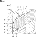
- Fig. 4 shows a perspective detailed view of the outer rotor 6 and a rotary vane 12 of the gerotor pump 1 according to the first embodiment of the present invention. In the Fig. 4 The case back 21 is also shown.
- the rotary valve 12 is clearly positioned on the housing base 21.
- a height 27 of the rotary valve 12 is less than a height 28 of the outer rotor 6 with respect to the axial direction 30.
- the height 27 of the rotary valve 12 is between 90% and 98% of the height 28 of the outer rotor 6.
- fluid indicated by a fluid flow 29, can flow particularly easily from the inlet pump chamber 3 on the rotary valve 12 into the housing space 11 between the outer rotor 6 and the housing 10.
- the aforementioned fluid between the housing cover 20 and the outer rotor 6 and the inner rotor 7 (in the axial gap) can flow particularly easily into the housing space 11, i.e. with low viscous friction.
- the rotary valve 12 also has a rounded side surface 31 on the housing side, which reduces friction between the rotary valve 12 and the housing 10.
- Fig. 5 shows a schematic cross-sectional view of a gerotor pump 1 according to a second embodiment of the present invention.
- the pressure elements are designed as pistons 32.
- the gerotor pump 1 has at least two, in the present case six pistons 32.
- the openings 16 are designed as radial bores in the outer circumference 13 of the outer rotor 6.
- the pistons 32 are radially displaceable and seal a radial housing-side end 34 of the respective opening 16.
- the openings 16 are fluidically connected to the inlet pump chamber 3 and/or to the outlet pump chamber 5.
- This essentially results in an L-shaped bore in the outer rotor 6, with the respective piston 32 being arranged in the radial bore.
- This allows the fluid which is between the housing cover 20 and the outer rotor 6 (in the axial gap) to flow through the axial part of the bores into the openings 6.
- the axial bore is fluidly connected to the axial gap.
- piston pressure chambers 33 are formed between the radial inner side 17 of the opening 16 and the respective pistons 32.
- the pistons 32 are pressed radially into the openings 16, whereby the fluid is pressurized by the piston 32.
- This resulting pressure exerts a force on the radial inner side 17 of the opening 16 and thus on the outer rotor 6, whereby it is positioned against the inner rotor 7.
- the piston pressure chambers 33 are secondary pressure areas, similar to the pressure chambers 14, which are generated by the rotary valves 12.
- the pistons 32 can also create the pressure chambers 14 between the outer rotor 6 and the housing 10 in the housing space 11.
- the pistons 32 can have a corresponding height 27 of the rotary slide valves 12.
- the outer rotor 6 is not arranged centrally in the housing space 11, at least when the pump 1 is at rest.
- the outer rotor 6 can be arranged centrally in the housing space 11 when the pump 1 is at rest.
- a pressure difference between the inlet 2 and the outlet 4 causes the outer rotor 6 to be turned on when the pump 1 is operating.
- This turning particularly at high pressures, also causes the outer rotor 6 to be arranged non-centrally in the housing space 11, so that even in such a case the secondary pressure areas are formed during operation of the pump 1.
- these secondary pressure areas at least partially counteract the turning by the primary pressure areas, so that the gap between the outer rotor 6 and the inner rotor 7 is reduced at least during operation of the pump 1 and its efficiency is increased.
- the Figures 6 and 7 each show schematic sectional views of a gerotor pump 1 according to a third embodiment of the present invention.
- the housing 10 has a plurality, here four, openings 37, also called housing openings 37, along its inner circumference 36.
- a radially displaceable pressure element is arranged as a rotary slide valve 35.
- Each rotary slide valve 35 rests, particularly during operation of the gerotor pump 10, along the circumferential direction 18 on at least one inner surface 41 of the housing 10 or the housing opening 37.
- Each rotary valve 35 protrudes from a radial inner side 39 of the housing opening 37 and is arranged on the outer rotor 6. As can be seen in particular from Fig. 7 It can be seen that each rotary valve 35 is positioned or preloaded against the outer rotor 6 by a spring element 38, here a leaf spring.
- a height 27 of the rotary valve 35 with respect to the axial direction 30 is less than a height 42 of the housing 10.
- the height 27 of the rotary valve 35 is in particular less than a height 28 of the outer rotor 6.
- the housing cover 20 or the housing base 21 can have grooves which guide the fluid into the housing opening 37.
- the spring element 38 can be functionally replaced at least partially by fluid in the housing opening 37, which positions the rotary slide 35 against the outer rotor 6.
- the housing 10 can have one or more housing grooves 43, which in Fig. 6 is shown in dashed lines.
- This housing groove 43 is an axial recess in the housing 10 and connects two openings 37 to one another so that they are fluidically connected to one another.
- the housing groove 43 shown connects the two openings 37 to the housing space 11 so that the openings 37 are fluidically connected to it.
- housing grooves 43 can be arranged in the housing 10.
- two housing grooves 43 can be formed, each of which connects two of the four openings 37 to one another.
- two of the openings 37 can be fluidically connected to the inlet pump chamber 3 and the other two of the openings 37 can be fluidically connected to the outlet pump chamber 5, without these being fluidically short-circuited (in pairs).
- the rotary valves 35 of the present embodiment provide the same advantages as the rotary valves 12 of the first embodiment.
- the rotary valves 35 create pressure chambers 14 in the housing space 11 radially between the outer rotor 6 and the housing 10, whereby the outer rotor 6 is adjusted.
- the gerotor pump 1 according to the present embodiment can be combined with the gerotor pump 1 according to the first and/or the second embodiment.
- the rotary vanes 35 of the present embodiment apart from being arranged in the housing 10, and their associated openings 37 can have similar or identical configurations to the pressure elements 12, 32 and openings 16 of the first two embodiments.
- the present rotary vanes 35 can also be designed as pistons which position the outer rotor 6 against the inner rotor 7.
- This combination can be combined particularly advantageously with the aforementioned configuration in which the housing 10 has one or more housing grooves 43, in addition to or as an alternative to the possible grooves in the housing cover 20 or in the housing base 21.
- the invention also relates to a motor-pump unit 100.
- Fig. 8 shows a schematic block diagram of the motor-pump unit 100 according to an embodiment of the present invention.
- the motor-pump unit 100 comprises a motor 101 and a gerotor pump 1 according to the above embodiments.
- the motor 101 is designed to rotate the inner rotor 7 to operate the gerotor pump 1.
- the motor 101 is connected to the inner rotor 7 by means of a shaft 102 (see also Fig. 2 ) mechanically connected to the inner rotor 7.
- the motor-pump unit 100 has a particularly good efficiency and is more tolerance-independent.
Landscapes
- Engineering & Computer Science (AREA)
- Mechanical Engineering (AREA)
- General Engineering & Computer Science (AREA)
- Details And Applications Of Rotary Liquid Pumps (AREA)
- Rotary Pumps (AREA)
Abstract
Description
- Die Erfindung betrifft eine Gerotorpumpe zum Fördern eines Fluides und eine Motor-Pumpen-Einheit, welche die Gerotorpumpe aufweist.
- Herkömmliche Gerotorpumpen, auch bekannt als "Zahnringpumpe" oder "Eatonpumpe" weisen einen drehbaren Außenrotor und einen drehbaren Innenrotor auf, wobei der Innenrotor radial innerhalb des Außenrotors angeordnet ist. Herkömmlicherweise wird der Innenrotor durch einen Motor angetrieben. Dabei ist der Innenrotor als Zahnrad und der Außenrotor als Zahnring ausgebildet, wobei der Innenrotor und der Außenrotor voneinander verschiedene Drehachsen aufweisen. Dadurch läuft der Außenrotor exzentrisch an einer Außenverzahnung des Innenrotors. Bedingt durch die sich verändernden Volumina zwischen den Zahnlücken zwischen Innenrotor und Außenrotor bilden sich Druckbereiche aus, auch Pumpkammern genannt, mittels welcher das Fluid gefördert wird.
- "Fundamentals of Designing Hydraulic Gear Machines" von Jaroslaw Stryczek (ISBN: 978-83-01-21226-1) und "Axial clearance compensation in the gerotor pump" von Jaroslaw Stryczek und Slawomir Bednarczyk aus "the 19th International Conference on Hydraulics and Pneumatics, Prague, September 29 - October 1, 2008" beschreiben herkömmliche Axialkompensation in Gerotorpumpen mittels Kompensationsplatten (engl.: "compensation plates").
- Die herkömmlich bekannten Gerotorpumpen haben jedoch den Nachteil, dass Fertigungstoleranzen zu einem sogenannten Zahnkopfspiel zwischen Zähnen des Innenrotors und des Außenrotors führen. Dadurch entsteht ein Spalt insbesondere zwischen sich gegenüberliegenden Zähnen des Innenrotors und des Außenrotors. Dieses Zahnkopfspiel liegt bereits im Ruhezustand der Pumpe vor, also auch während die Pumpe nicht in Betrieb genommen ist. Im Betrieb der Pumpe steigt der Druck und vergrößert den Spalt zwischen Innenrotor und Außenrotor weiter, sodass eine innere Leckage verursacht wird und der Wirkungsgrad der Pumpe fällt.
- Es ist Aufgabe der Erfindung, eine Gerotorpumpe bereitzustellen, welche ein Zahnkopfspiel zwischen Innenrotor und Außenrotor im Betrieb durch Radialkompensation verringern kann und dadurch einen hohen Wirkungsgrad aufweist. Es ist außerdem Aufgabe der Erfindung, eine Motor-Pumpen-einheit bereitzustellen, welche ebenfalls einen hohen Wirkungsgrad aufweist.
- Die Lösung dieser Aufgabe erfolgt durch die Merkmale der nebengeordneten Ansprüche. Die Unteransprüche haben vorteilhafte Ausgestaltungen der Erfindung zum Inhalt.
- Die Lösung dieser Aufgabe erfolgt insbesondere durch eine Gerotorpumpe gemäß Anspruch 1. Die Gerotorpumpe ist zum Fördern eines Fluides von einer mit einem Einlass verbundenen Einlasspumpkammer zu einer mit einem Auslass verbundenen Auslasspumpkammer der Gerotorpumpe ausgestaltet und geeignet. Dabei weist die Gerotorpumpe einen drehbaren Außenrotor und einen drehbaren Innenrotor auf. Der Innenrotor ist radial innerhalb des Außenrotors angeordnet. Der Innenrotor und der Außenrotor weisen voneinander verschiedene Drehachsen auf. Des Weiteren weist die Gerotorpumpe ein Gehäuse mit einem Gehäuseraum auf, in welchem der Außenrotor und der Innenrotor aufgenommen sind. Ferner weist die Gerotorpumpe eine Mehrzahl von radial verschiebbaren Druckelementen auf. Die Druckelemente sind an einem Außenumfang des Außenrotors angeordnet. Im Betrieb der Gerotorpumpe liegen die Druckelemente am Gehäuse an, sodass zwischen Außenrotor und Gehäuse und/oder zwischen Außenrotor und den Druckelementen Druckkammern ausgebildet sind. Die Druckkammern sind mit der Einlasspumpkammer und/oder mit der Auslasspumpkammer fluidverbunden.
- Die Druckkammern werden im Betrieb der Pumpe zwischen dem Außenrotor und dem Gehäuse und/oder zwischen dem Außenrotor und den Druckelementen ausgebildet. Aus diesen Druckkammern resultiert im Betrieb der Pumpe eine Kraft, welche den Außenrotor radial gegen den Innenrotor drückt bzw. anstellt. Dieser Effekt wird auch als "Radialkompensation" bezeichnet. Damit wird ein Spalt zwischen Außenrotor und Innenrotor verkleinert, insbesondere bei steigenden Drücken im Betrieb der Pumpe, sodass der Wirkungsgrad erhöht wird.
- Die Druckkammern sind vorteilhafterweise als entsprechende Druckbereiche des zu fördernden Fluides definiert, welche separat bzw. zusätzlich zu den Druckbereichen zwischen Außenrotor und Innenrotor sind, durch welche das Fluid hauptsächlich gefördert wird. Zur Unterscheidung werden die zwischen Außenrotor und Innenrotor ausgebildeten Druckbereiche zur hauptsächlichen Fluidförderung auch "primäre Druckbereiche" und die vorstehend definierten Druckkammern zur Radialkompensation, welche von den Druckelementen erzeugt werden, auch "sekundäre Druckbereiche" genannt.
- In besonderen Ausführungen weist die Gerotorpumpe mindestens zwei Druckelemente auf. Besonders bevorzugt weist die Gerotorpumpe mindestens drei bis sieben, weiter bevorzugt mindestens acht Druckelemente auf. Besonders bevorzugt weist die Gerotorpumpe genau acht Druckelemente oder genau sechs Druckelemente auf.
- In einer vorteilhaften Ausgestaltung weist das Gehäuse entlang seines Innenumfangs eine Mehrzahl von Gehäuseöffnungen auf, in welchen jeweils ein Druckelement zumindest teilweise angeordnet ist. Die Gehäuseöffnungen (nachstehend auch als "Öffnungen" bezeichnet) sind vorteilhafterweise Schlitze und/oder Bohrungen. Vorteilhafterweise liegen die Druckelemente jeweils entlang einer Umfangsrichtung des Gehäuses innerhalb der Gehäuseöffnung am Gehäuse an. Die Druckelemente liegen am Außenumfang des Außenrotors an beziehungsweise sind gegen den Außenumfang des Außenrotors angestellt oder vorgespannt.
- Die Gehäuseöffnungen sind vorteilhafterweise jeweils mit der Einlasspumpkammer und/oder mit der Auslasspumpkammer fluidverbunden. Mit anderen Worten erreicht das zu fördernde Fluid die Öffnungen. Dies hat den Vorteil, dass die Druckelemente durch einen hydraulischen Druck in den Öffnungen beim Betrieb der Gerotorpumpe gegen den Außenrotor angestellt werden, um somit die sekundären Druckbereiche zu bilden. Das Vorsehen der Druckelemente in Gehäuseöffnungen hat außerdem den Vorteil, dass Anpassungen des Innenrotors oder des Außenrotors nicht zwingend notwendig sind, wodurch die Herstellung der Gerotorpumpe vereinfacht wird.
- Vorteilhafterweise weist die Gerotorpumpe eine Mehrzahl von Federelementen auf, wobei die Federelemente jeweils in einer der Gehäuseöffnungen angeordnet sind. Die Federelemente spannen das jeweilige Druckelement (in derselben Gehäuseöffnung) zum Außenrotor vor. Mit anderen Worten drückt das Federelement das Druckelement gegen den Außenrotor.
- Die Federelemente sind vorteilhafterweise Schraubenfedern oder Blattfedern, wobei verschiedene Arten von Federelementen in verschiedenen Gehäuseöffnungen angeordnet sein können. Des Weiteren können mehrere Federelemente in einer Gehäuseöffnung angeordnet sein. Beispielsweise können zwei Schraubenfedern in einer Gehäuseöffnung angeordnet sein. Alternativ oder in anderen Gehäuseöffnungen kann eine (einzige) Blattfeder in der Gehäuseöffnung angeordnet sein.
- In einer vorteilhaften Ausgestaltung weist der Außenrotor entlang seines Außenumfangs eine Mehrzahl von Öffnungen auf, in welchen jeweils ein Druckelement zumindest teilweise angeordnet ist. Die Öffnungen sind vorteilhafterweise Schlitze und/oder Bohrungen. Die Öffnungen sind jeweils mit der Einlasspumpkammer und/oder mit der Auslasspumpkammer fluidverbunden. Mit anderen Worten erreicht das zu fördernde Fluid die Öffnungen. Dies hat den Vorteil, dass die Druckelemente, welche zwischen dem Außenrotor und dem Gehäuse sind, zumindest teilweise von dem Außenrotor aufgenommen werden können. Dadurch wird vorteilhafterweise die Baugröße der Gerotorpumpe verringert.
- Die Druckelemente sind radial verschiebbar und vorteilhafterweise in den vorgenannten Öffnungen/Gehäuseöffnungen zumindest teilweise angeordnet. In einem Fall, in welchem die Druckelemente in Öffnungen des Außenrotors angeordnet sind, können die Druckelemente beispielsweise im Ruhezustand der Pumpe vollständig innerhalb der jeweiligen Öffnung angeordnet sein und beim Betrieb der Pumpe durch eine wirkende Zentrifugalkraft radial nach außen verschoben werden, um lediglich teilweise in der jeweiligen Öffnung angeordnet zu sein. Die Druckelemente können beim Betrieb der Pumpe alle um ein gleiches oder ähnliches Maß aus ihrer jeweiligen Öffnung austreten oder um voneinander verschiedene Maße aus ihrer jeweiligen Öffnung austreten.
- In einem Fall, in welchem die Druckelemente in Gehäuseöffnungen angeordnet sind, können die Druckelemente beispielsweise im Ruhezustand der Pumpe vollständig innerhalb der jeweiligen Öffnung angeordnet sein. Beim Betrieb der Pumpe kann ein hydraulischer Druck der Einlasspumpkammer und/oder der Auslasspumpkammer, welche mit der Öffnung fluidverbunden sind, das jeweilige Druckelement gegen den Außenrotor anstellen.
- In einem weiteren Beispiel können die Druckelemente mittels der Federelemente auch im Ruhezustand der Pumpe gegen den Außenrotor angestellt beziehungsweise vorgespannt sein.
- In einer vorteilhaften Ausgestaltung weist das Gehäuse einen Gehäusedeckel und einen Gehäuseboden auf, zwischen (entlang axialer Richtung) welchen der Innenrotor und der Außenrotor angeordnet sind. Entlang der axialen Richtung sind zwischen Gehäusedeckel und Innenrotor sowie Außenrotor und zwischen Gehäuseboden und Innenrotor sowie Außenrotor Abstände vorgesehen, welche Teile der Einlasspumpkammer und der Auslasspumpkammer bilden, sodass das zu fördernde Fluid den Innenrotor und den Außenrotor axial umgibt.
- In bevorzugten Ausführungsformen weisen der Gehäusedeckel und/oder der Gehäuseboden vorteilhafterweise Nuten auf, welche zusammen mit Zwischenräumen zwischen dem Innenrotor und dem Außenrotor die Einlasspumpkammer und die Auslasspumpkammer bilden. Die Nuten verlaufen vorteilhafterweise zumindest teilweise entlang einer Umfangsrichtung des Außenrotors. In einer Draufsicht, definiert als eine Sicht auf einen Querschnitt des Außenrotors und des Innenrotors senkrecht zu den Drehachsen, sind die Nuten jeweils an zwei Seiten in Umfangsrichtung des Einlasses und/oder des Auslasses angeordnet und erstrecken sich entlang der Umfangsrichtung von dem Einlass und/oder von dem Auslass weg. Durch die Nuten wird ein Volumen der Einlasspumpkammer und/oder Auslasspumpkammer zwischen Gehäusedeckel/Gehäuseboden und dem Außenrotor und/oder Innenrotor vorteilhafterweise erhöht, wodurch eine viskose Reibung mit dem Fluid verringert und somit Flächen mit notwendig geringem Spiel/Toleranzen reduziert werden können und dadurch der Wirkungsgrad der Pumpe steigt.
- In einer bevorzugten Ausgestaltung sind die Druckelemente jeweils Drehschieber. Dabei sind die als Drehschieber ausgestalteten Druckelemente vorzugsweise im Wesentlichen rechteckig und plattenförmig. Vorteilhafterweise weisen die Drehschieber abgerundete Ecken auf.
- Weiter vorteilhaft ist es, wenn zumindest eine gehäuseseitige Seitenfläche der in Öffnungen des Außenrotors angeordneten Drehschiebern, insbesondere die gehäuseseitige Seitenfläche, welche mit dem Gehäuse in Kontakt kommt, abgerundet ist. Dadurch wird eine Reibung zwischen dem Drehschieber und dem Gehäuse verringert. Weiter vorteilhaft ist es, wenn zumindest eine außenrotorseitige Seitenfläche der in Gehäuseöffnungen angeordneten Drehschiebern, insbesondere die außenrotorseitige Seitenfläche, welche mit dem Außenrotor in Kontakt kommt, abgerundet ist. Dadurch wird eine Reibung zwischen dem Drehschieber und dem Außenrotor verringert.
- Vorteilhafterweise ist eine Höhe der Drehschieber entlang einer Axialrichtung des Außenrotors geringer als eine Höhe des Außenrotors oder geringer als eine Höhe des Gehäuses in Axialrichtung. Mit anderen Worten ist vorteilhafterweise eine Tiefe in Axialrichtung der Öffnung bzw. des Schlitzes oder der Bohrung im Außenrotor oder im Gehäuse größer als eine Höhe des jeweiligen Drehschiebers. Dies hat den Vorteil, dass das zu fördernde Fluid von der Einlasspumpkammer auf dem Drehschieber entlang in den Gehäuseraum zwischen Außenrotor und Gehäuse oder in die Gehäuseöffnung mit besonders geringer viskosen Reibung fließen kann. Durch eine Einstellung der Höhe der Drehschieber kann eine Fluidmenge, welche wie vorstehend beschrieben auf dem Drehschieber fließt, gesteuert werden, sodass ein Druck zwischen den durch die Drehschieber erzeugten Druckkammern gesteuert werden kann. In besonderen Ausgestaltungen weisen die Drehschieber unterschiedliche Höhen auf, oder weisen alle die gleiche Höhe auf.
- In manchen besonderen Ausführungen beträgt eine Höhe der Drehschieber 90%, bevorzugt 95%, noch bevorzugter 98%, der Höhe des Außenrotors oder der Höhe des Gehäuses. Bevorzugt ist ein Unterschied in Höhen zwischen dem Außenrotor oder dem Gehäuse und den Drehschiebern mehr als (lediglich) durch Fertigungstoleranzen bedingt. Dadurch lässt sich eine besonders gute Auswirkung der Drehschieber sowie Verringerung der Reibung erzielen. Alternativ kann die Höhe der Drehschieber etwa 50% der Höhe des Außenrotors oder der Höhe des Gehäuses betragen.
- Die vorgenannte Höhe ist insbesondere als (axiale) Länge der vorgenannten gehäuseseitigen Seitenfläche oder der vorgenannten außenrotorseitigen Seitenfläche zu verstehen.
- In einer vorteilhaften Ausgestaltung trennen die Drehschieber den Gehäuseraum entlang einer Umfangsrichtung des Außenrotors zumindest Abschnittsweise. Im Betrieb sind zumindest zwischen den Drehschiebern entlang der Umfangsrichtung Druckkammern gebildet. Diese Druckkammern sind vorzugsweise zusätzlich zu den vorstehend erläuterten primären Druckbereichen (zwischen Innenrotor und Außenrotor) gebildet. Diese Druckkammern sind vorteilhafterweise entlang der Umfangsrichtung zwischen den Drehschiebern und in Radialrichtung zwischen dem Außenrotor und dem Gehäuse gebildet. Beim Betrieb der Pumpe sind die Fluiddrücke in den Druckkammern vorteilhafterweise mit Bezug auf die Axialrichtung bzw. mit Bezug auf die Drehachsen des Außenrotors und/oder des Innenrotors nicht achsensymmetrisch. Mit anderen Worten ist der Druck, welcher innerhalb der Druckkammern entsteht, zwischen zumindest manchen der Druckkammern unterschiedlich. Dadurch entsteht vorteilhafterweise eine Kraft, welche den Außenrotor gegen den Innenrotor anstellt, sodass der Spalt zwischen diesen verringert und dadurch der Wirkungsgrad erhöht wird.
- In einer vorteilhaften Ausgestaltung sind die Druckelemente jeweils Kolben. Vorteilhafterweise ist dabei die jeweilige Öffnung als Bohrung ausgestaltet, in welcher der jeweilige Kolben radial verschiebbar angeordnet ist. Die Öffnung ist mit der Einlasspumpkammer und/oder der Auslasspumpkammer fluidverbunden.
- In einem Fall, in welchem die Kolben im Außenrotor angeordnet sind, wird beim Betrieb der Pumpe der Kolben radial nach innen verschoben, sodass ein Druck auf das in der Öffnung befindliche Fluid ausgeübt wird. Dieser Druck übt wiederrum eine Kraft auf den Außenrotor aus, welche den Außenrotor gegen den Innenrotor anstellt und den Spalt verringert, sodass der Wirkungsgrad erhöht ist. In einem Fall, in welchem die Kolben im Gehäuse angeordnet sind, wird beim Betrieb der Pumpe der Kolben durch den in der Einlasspumpkammer oder Auslasspumpkammer herrschenden Druck radial nach innen verschoben, sodass der Kolben den Außenrotor gegen den Innenrotor anstellt und den Spalt verringert, sodass der Wirkungsgrad erhöht ist.
- Vorteilhafterweise dichtet der jeweilige Kolben ein radial gehäuseseitiges Ende der Öffnung im Außenrotor oder dichtet ein radial außenrotorseitiges Ende der Öffnung im Gehäuse ab. Mit anderen Worten weist jede Öffnung im Außenrotor, in welcher ein solcher Kolben angeordnet ist, ein radial inneres Ende (innenrotorseitiges) Ende und ein radial äußeres (gehäuseseitiges) Ende auf, wobei der Kolben verschiebbar zumindest teilweise aus dem gehäuseseitigen Ende ragt. Eine radiale Innenseite der Öffnung im Außenrotor, welche eine Innenseite der Öffnung an ihrem radialen inneren Ende ist und welche mit der Einlasspumpkammer und/oder mit der Auslasspumpkammer fluidverbunden ist, bildet mit dem Kolben eine Kolbendruckkammer. In einem Fall, in welchem der Kolben in einer Öffnung des Gehäuses angeordnet ist, ist das radial innere Ende der Öffnung außenrotorseitig und das radial äußere Ende der Öffnung radial weiter außen im Gehäuse angeordnet. Die Kolbendruckkammer wird dabei zwischen dem radial äußeren Ende der Gehäuseöffnung und dem Kolben, welcher zwischen Gehäuse und Außenrotor angeordnet ist, gebildet.
- Mit anderen Worten bilden der Kolben und die Öffnung zusammen eine Kolben-ZylinderAnordnung. Die Kolbendruckkammer übt vorteilhafterweise die vorstehend erläuterte Anstellkraft auf den Außenrotor aus, sodass der Wirkungsgrad der Pumpe erhöht ist.
- Das radial innere Ende der Öffnung im Außenrotor oder das radial äußere Ende der Gehäuseöffnung ist vorzugsweise mit dem Zwischenraum zwischen Außenrotor und dem Gehäusedeckel oder, in Abhängigkeit der axialen Orientierung der Öffnung, mit dem Zwischenraum zwischen Außenrotor und dem Gehäuseboden verbunden, sodass das Fluid in diesem Zwischenraum in die Öffnung fließen kann.
- Vorteilhafterweise sind die Ausgestaltung der Druckelemente als Drehschieber und als Kolben kombinierbar. Beispielsweise ist dabei zumindest ein Druckelement als Drehschieber und zumindest ein Druckelement als Kolben ausgestaltet. Weiterhin kann ein Druckelement funktional gleichzeitig als Drehschieber und als Kolben ausgestaltet sein, beispielsweise durch eine Ausgestaltung des Drehschiebers als Kolben mit einer beispielhaften Höhe in Axialrichtung von mindestens 50 % oder 90%, oder einer der weiteren, oben zu den Drehschiebern genannten Werte, der Höhe des Außenrotors. Vorteilhafterweise trennen dabei solche Kolben den Gehäuseraum entlang der Umfangsrichtung des Außenrotors zumindest abschnittsweise und bilden entlang der Umfangsrichtung zusätzlich zu den Kolbendruckkammern weitere Druckkammern zwischen dem Außenrotor und dem Gehäuse.
- In einer alternativen Ausgestaltung weisen der Außenrotor und der Gehäuseraum voneinander verschiedene Mittelpunktachsen senkrecht zur Radialrichtung auf. Dabei stimmen insbesondere die Mittelpunktachse des Gehäuseraums und die Drehachse des Außenrotors nicht überein. Mit anderen Worten ist der Außenrotor nicht mittig in dem Gehäuseraum angeordnet. Dies hat den Vorteil, dass die sekundären Druckkammern asymmetrisch sind und eine aus diesen Druckkammern resultierende Kraft den Außenrotor gegen den Innenrotor anstellt, sodass der Wirkungsgrad erhöht ist. Durch die abweichenden Mittelpunktachsen wird beim Betrieb der Pumpe eine angulare oder umfängliche Position eines maximalen erzeugten Drucks in den sekundären Druckkammern entsprechend geändert, sodass eine resultierende Druckkraft aus allen sekundären Druckkammern der resultierenden Druckkraft der primären Druckkammern, welche den Außenrotor anstellt, entgegengewirkt. Wird die Druckkraft aus den primären Druckkammern mehr als kompensiert (mehr als vollständig entgegengewirkt), so wird der Spalt zwischen Außenrotor und Innenrotor verkleinert, wodurch der Wirkungsgrad weiter gesteigert werden kann.
- Vorzugsweise weist der Außenrotor zumindest eine, insbesondere eine Mehrzahl von entlang der Umfangsrichtung verteilten, Außenrotornut(en) auf. Die Außenrotornuten sind insbesondere jeweils entlang der Umfangsrichtung zwischen den vorgenannten Öffnungen gebildet. Die Außenrotornuten verringern vorteilhafterweise eine viskose Reibung mit dem Fluid zwischen Außenrotor und Gehäusedeckel und/oder Gehäuseboden. Die Außenrotornuten können auf einer oder beiden axialen Seiten des Außenrotors (gehäusebodenseitig und/oder gehäusedeckelseitig) gebildet sein. Die Außenrotornuten sind dabei insbesondere als entlang der Umfangsrichtung längliche und in Axialrichtung tiefe Vertiefungen im Außenrotor gebildet. Vorzugsweise kann der Innenrotor ebenfalls solch entsprechende Nuten (Innenrotornuten) aufweisen.
- Vorzugsweise weist das Gehäuse zumindest eine, insbesondere eine Mehrzahl von entlang der Umfangsrichtung verteilten, Gehäusenut(en) auf. Die Gehäusenuten sind insbesondere jeweils entlang der Umfangsrichtung zwischen den vorgenannten Gehäuseöffnungen gebildet. Die Gehäusenuten verringern vorteilhafterweise eine viskose Reibung mit dem Fluid zwischen Gehäuse und Gehäusedeckel und/oder Gehäuseboden. Die Gehäusenuten können auf einer oder beiden axialen Seiten des Gehäuses (gehäusebodenseitig und/oder gehäusedeckelseitig) gebildet sein. Die Gehäusenuten sind dabei insbesondere als entlang der Umfangsrichtung längliche und in Axialrichtung tiefe Vertiefungen im Gehäuse gebildet. Vorzugsweise können der Innenrotor und/oder der Außenrotor solche Nuten aufweisen.
- In manchen Ausführungen weist die Gerotorpumpe außerdem zumindest eine Kompensationsplatte (engl: "compensation plate") auf, welche (jeweils) in Axialrichtung zwischen Gehäusedeckel und/oder Gehäuseboden und Innenrotor und/oder Außenrotor angeordnet ist/sind und eine Axialkompensation der Gerotorpumpe ermöglicht/ermöglichen. Dadurch weist die Gerotorpumpe vorteilhafterweise Radialkompensation und Axialkompensation auf, wodurch der Wirkungsgrad besonders hoch ist.
- Die Erfindung betrifft außerdem eine Motor-Pumpen-Einheit. Die Motor-Pumpen-Einheit weist eine Gerotorpumpe gemäß einem der vorstehenden bevorzugten Ausgestaltungen auf. Des Weiteren weist die Motor-Pumpen-Einheit einen Motor auf, welcher mit dem Innenrotor verbunden ist und eingerichtet ist, den Innenrotor zum Betreiben der Gerotorpumpe zu rotieren. Der Motor ist insbesondere mittels einer Welle mechanisch mit dem Innenrotor verbunden. Die Motor-Pumpen-Einheit weist einen erhöhten Wirkungsgrad auf.
- Die Gerotorpumpe und die Motor-Pumpen-Einheit weisen außerdem die folgenden Vorteile auf. Durch das Ausgleichen von Toleranzen (Radialkompensation oder Radialkompensation mit Axialkompensation) können die Komponenten dieser deutlich kostenreduziert hergestellt werden, da Herstellungstoleranzen deutlich ausgeweitet werden können. Durch den höheren Wirkungsgrad können diese in höheren Druckbereichen verwendet werden. Des Weiteren ist durch die Radialkompensation eine Performancestabilität über verschiedene Drücke erhöht. Des Weiteren ist für die vorstehend erläuterte Radialkompensation keine weitere Steuerung notwendig, da die Radialkompensation selbststeuernd durch ein hydraulisches Wirkprinzip funktioniert.
- Die vorstehend erläuterten bevorzugten Ausgestaltungen und Wirkungen sind unabhängig von einer Drehrichtung des Außenrotors bzw. des Innenrotors.
- Weitere Einzelheiten, Vorteile und Merkmale der vorliegenden Erfindung ergeben sich aus nachfolgender Beschreibung von Ausführungsbeispielen anhand der Zeichnung. Es zeigt:
-
Fig. 1 eine schematische Querschnittsansicht einer Gerotorpumpe gemäß einer ersten Ausführungsform der vorliegenden Erfindung; -
Fig. 2 eine schematische Draufsicht der Gerotorpumpe gemäß der ersten Ausführungsform der vorliegenden Erfindung; -
Fig. 3 eine perspektivische Detailansicht eines Außenrotors der Gerotorpumpe gemäß der ersten Ausführungsform der vorliegenden Erfindung; -
Fig. 4 eine perspektivische Detailansicht des Außenrotors und eines Drehschiebers der Gerotorpumpe gemäß der ersten Ausführungsform der vorliegenden Erfindung; -
Fig. 5 eine schematische Querschnittsansicht einer Gerotorpumpe gemäß einer zweiten Ausführungsform der vorliegenden Erfindung; -
Fig. 6 eine schematische Querschnittsansicht einer Gerotorpumpe gemäß einer dritten Ausführungsform der vorliegenden Erfindung; -
Fig. 7 eine weitere schematische Schnittansicht der Gerotorpumpe gemäß der dritten Ausführungsform der vorliegenden Erfindung; und -
Fig. 8 ein schematisches Blockdiagramm einer Motor-Pumpen-Einheit gemäß einer Ausführungsform der vorliegenden Erfindung. -
Fig. 1 zeigt eine schematische Querschnittsansicht einer Gerotorpumpe 1 gemäß einer ersten Ausführungsform der vorliegenden Erfindung. - Die Gerotorpumpe 1 (nachfolgend "Pumpe 1") zum Fördern eines Fluides weist einen drehbaren Innenrotor 7 und einen drehbaren Außenrotor 6 auf. Der Innenrotor 7 ist als Zahnrad ausgebildet. Der Außenrotor 6 ist als Zahnring ausgebildet.
- Der Innenrotor 7 und der Außenrotor 6 sind in einem Gehäuseraum 11 eines Gehäuses 10 aufgenommen. Dabei ist der Innenrotor 7 entlang einer Radialrichtung 15 innerhalb des Außenrotors 6 angeordnet.
- Der Innenrotor 7 ist um eine Innenrotor-Drehachse 8 drehbar, während der Außenrotor 6 um eine Außenrotor-Drehachse 9 drehbar ist. Wie aus
Fig. 1 ersichtlich sind die Drehachsen 8, 9 voneinander verschieden, also parallel zueinander angeordnet. Im Betrieb der Pumpe 1 bewirkt eine Drehung des Innenrotors 7 eine Drehung des Außenrotors 6. Der Betrieb der Pumpe 1 wird nachstehend mit Bezug aufFig. 2 erläutert. - Wie aus
Fig. 1 weiter ersichtlich ist der Außenrotor 6 in der vorliegenden Ausführungsform zumindest im Ruhezustand der Pumpe 1 nicht mittig in dem Gehäuseraum 11 angeordnet. Mit anderen Worten sind hierbei Mittelpunktachsen des Gehäuseraums 11 und des Außenrotors 6 hierbei voneinander verschieden. Vorliegend ist der Innenrotor 7 mittig im Gehäuseraum 11 angeordnet, sodass eine Mittelpunktachse des Gehäuseraums 11 mit der Innenrotor-Drehachse 8 zusammenfällt. Die Mittelpunktachse des Außenrotors 6 fällt im vorliegenden Fall mit der Außenrotor-Drehachse 9 zusammen. - Der Außenrotor 6 weist zumindest zwei, hier acht, Öffnungen 16 an seinem Außenumfang 13 auf. Die Öffnungen 16 sind, wie nachstehend mit Bezug auf
Fig. 3 &4 erläutert, vorliegend Schlitze. Die Öffnungen 16 sind im vorliegenden Fall bevorzugt über den Außenumfang 13 des Außenrotors 6 gleichverteilt, also symmetrisch angeordnet. In einer alternativen besonderen Ausgestaltung können die Öffnungen 16 asymmetrisch entlang des Außenumfangs 13 angeordnet sein, sodass zwischen zumindest zwei Paaren von Öffnungen 16 verschiedene Abstände entlang des Außenumfangs 13 gebildet sind. - In jeder Öffnung ist ein Drehschieber 12 als Druckelement angeordnet. Die Drehschieber 12 sind radial innerhalb der jeweiligen Öffnungen 16 verschiebbar. Bei einer Drehung des Außenrotors 6 bewirkt eine aus der Drehung resultierende Zentrifugalkraft, dass die Drehschieber 12 aus der jeweiligen Öffnungen 12 ragen und am Gehäuse 10 anliegen.
- Wie nachstehend erläutert wird (siehe
Fig. 2 ) befindet sich im Betrieb der Pumpe 1 das zu fördernde Fluid teilweise auch in dem Gehäuseraum 11 zwischen dem Außenrotor 6 und dem Innenrotor 7. Beim Drehen des Außenrotors 6 bilden die Drehschieber 12 Druckkammern 14. Die Druckkammern 14 sind hierbei in Radialrichtung 15 zwischen dem Außenrotor 7 und dem Gehäuse 10 und entlang einer Umfangsrichtung 18 zwischen den Drehschiebern 12 gebildet. - Durch eine exzentrische Drehung des Außenrotors 6 innerhalb des Gehäuseraums 11 werden Druckkammern 14 mit unterschiedlichen Fluiddrücken gebildet. Diese verschiedenen Fluiddrücke an verschiedenen Umfangsstellen um den Außenrotor 6 herum erzeugen eine resultierende Kraft, welche den Außenrotor 6 gegen den Innenrotor 7 anstellt. In dem vorliegenden Fall bewirkt die resultierende Kraft vorteilhafterweise, dass der Außenrotor 6 entlang einer eingezeichneten -y Richtung gegen den Innenrotor 7 gedrückt wird. Dadurch wird vorteilhafterweise ein Spalt zwischen gegenüberliegenden Spitzen 19 des Außenrotors 6 und des Innenrotors 7 verringert. An den Stellen der gegenüberliegenden Spitzen 19 hat eine Verringerung des Spalts zwischen Außenrotor 6 und Innenrotor 7 die größte vorteilhafte Auswirkung zur Reduzierung einer inneren Leckage und zur Erhöhung des Wirkungsgrades der Pumpe 1. Dies wird weiter anhand
Fig. 2 erläutert. - Des Weiteren befindet sich das Fluid teilweise innerhalb der jeweiligen Öffnung 16 radial weiter innen als der jeweilige Drehschieber 12. Dabei befindet sich das Fluid in einem Öffnungsraum 24 zwischen einer radialen Innenseite 17 der Öffnung 16 und dem Drehschieber 12, sodass Öffnungsraum-Druckkammern 25 gebildet sind. Die Öffnungsraum-Druckkammern 25 sorgen für eine Federung der Drehschieber 12 und, wie nachstehend mit Bezug auf Ausführungsform zwei erläutert wird, für eine (weitere) Anstellkraft des Außenrotors 6. Alternativ oder zusätzlich dazu kann in dem jeweiligen Öffnungsraum 24 ein Federelement angeordnet sein, welches den Drehschieber 12 federt beziehungsweise radial vorspannt/anstellt.
-
Fig. 2 zeigt eine schematische Draufsicht der Gerotorpumpe 1 gemäß der ersten Ausführungsform der vorliegenden Erfindung. Dabei zeigt dieFig. 2 insbesondere einen Gehäusedeckel 20, welcher den Außenrotor 6, den Innenrotor 7 und den Gehäuseraum 11 bedeckt. Die von dem Gehäusedeckel 20 bedeckten Komponenten sind hierbei gestrichelt angedeutet. Zur besseren Übersicht sind die Drehschieber 12 in derFig. 2 nicht eingezeichnet. - Genauer weist die Pumpe 1 einen Gehäusedeckel 20 und einen Gehäuseboden 21 auf, wobei der Gehäuseboden 21 in der vorliegenden Ansicht nicht (direkt) sichtbar ist. Der Innenrotor 7 und der Außenrotor 6 sind, entlang einer Axialrichtung 30 des Außenrotors 6, welche mit der Außenrotor-Drehachse 9 zusammenfällt (vorliegend in z-Richtung), zwischen dem Gehäusedeckel 20 und dem Gehäuseboden 21 angeordnet. Dabei ist zwischen zumindest dem Gehäusedeckel 20 (und/oder zumindest dem Gehäuseboden 21) und dem Außenrotor 6 und dem Innenrotor 7 entlang der Axialrichtung 30 ein Abstand (Axialspalt) gebildet, sodass Fluid den Außenrotor 6 und den Innenrotor 7 umgibt.
- In dem Gehäuseboden 21 sind Öffnungen für einen Einlass 2 und für einen Auslass 4 gebildet. Das Fluid wird von der Pumpe 1 von dem Einlass 2 zu dem Auslass 4 gefördert. Wie außerdem aus
Fig. 2 ersichtlich weist der Gehäusedeckel 20 Nuten 22 auf, welche sich entlang der Umfangsrichtung 18 erstrecken und jeweils mit dem Einlass 2 oder dem Auslass 4 verbunden sind. Die Nuten 22 definieren zusammen mit Zwischenräumen 23 zwischen den Zähnen des Innenrotors 7 und des Außenrotors 6 (nachstehend "Volumina 23") eine Einlasspumpkammer 3 und eine Auslasspumpkammer 5 der Pumpe 1. Die Einlasspumpkammer 3 und die Auslasspumpkammer 5 der Pumpe 1 umfassen auch das vorgenannte Fluid bzw. Fluidvolumen in Axialrichtung 30 zwischen Gehäusedeckel 20 und/oder Gehäuseboden 21 und dem Außenrotor 6 und dem Innenrotor 7. - Im Betrieb der Pumpe 1 wird Fluid von dem Einlass 2 zum Auslass 4 entlang der Umfangsrichtung 18 gefördert. Wie an der
Fig. 2 erkennbar werden die Volumina 23 der Zwischenräume ausgehend vom Einlass 2 entlang der Umfangsrichtung 18 (vorliegend im Uhrzeigersinn) zunächst größer, sodass Fluid vom Einlass 2 angesaugt wird. Daraufhin, am Ende der Nut 22 in Umfangsrichtung 18 bleiben die Volumina 23 zunächst nahezu konstant, bevor die Volumina 23 daraufhin kleiner werden. Durch das Verkleinern der Volumina 23 zum Auslass 4 hin wird das Fluid mit Druck beaufschlagt und das Fluid aus dem Auslass 4 gefördert. Die hieraus resultierenden Druckbereiche des Fluides, mittels welcher das Fluid hauptsächlich zwischen Einlass 2 und Auslass 4 gefördert wird, werden auch "primäre Druckbereiche" genannt, während die Druckbereiche, welche von den vorstehend erläuterten Drehschiebern 12 gebildet werden, auch "sekundäre Druckbereiche" genannt werden. - An den Stellen der gegenüberliegenden Spitzen 19 ist eine Trennung der Volumina 23 und damit ein Wirkungsgrad der Pumpe 1 aufgrund der geringen Auflageflächen der Zähne gegenüber Fertigungstoleranzen sowie gegenüber einer Anstellung des Außenrotors 6 bei hohen Drücken des Fluides besonders empfindlich. Durch die Anstellung des Außenrotors 6 gegen den Innenrotor 7, bewirkt durch die mit Bezug auf
Fig. 1 erläuterten Drehschieber 12, wodurch ein Spalt zwischen den gegenüberliegenden Spitzen 19 verringert wird, wird der Wirkungsgrad der Pumpe 1 erhöht. -
Fig. 3 zeigt eine perspektivische Detailansicht des Außenrotors 6 der Gerotorpumpe 1 gemäß der ersten Ausführungsform der vorliegenden Erfindung. Wie ausFig. 3 ersichtlich ist der Außenrotor 6 im Wesentlichen ein Zahnring mit Schlitzen als Öffnungen 16 zur Aufnahme der Drehschieber 12. - Des Weiteren weist der Außenrotor 6 eine Mehrzahl von Außenrotornuten 26 auf, welche entlang der Umfangsrichtung 18 zwischen den Öffnungen 16 gebildet sind. Durch die Außenrotornuten 26 wird eine viskose Reibung mit dem Fluid zwischen dem Außenrotor 6 und dem Gehäusedeckel 20 und/oder dem Gehäuseboden 21 verringert.
-
Fig. 4 zeigt eine perspektivische Detailansicht des Außenrotors 6 und eines Drehschiebers 12 der Gerotorpumpe 1 gemäß der ersten Ausführungsform der vorliegenden Erfindung. In derFig. 4 ist außerdem der Gehäuseboden 21 dargestellt. - Wie aus der
Fig. 4 ersichtlich liegt der Drehschieber 12 auf dem Gehäuseboden 21 auf. Eine Höhe 27 des Drehschiebers 12 ist bezüglich der Axialrichtung 30 geringer als eine Höhe 28 des Außenrotors 6. Dabei beträgt die Höhe 27 des Drehschiebers 12 in besonderen Ausgestaltungen zwischen 90% und 98% der Höhe 28 des Außenrotors 6. - Durch die geringere Höhe 27 des Drehschiebers 12 kann Fluid, eingezeichnet durch einen Fluidfluss 29, von der Einlasspumpkammer 3 auf dem Drehschieber 12 in den Gehäuseraum 11 zwischen Außenrotor 6 und Gehäuse 10 besonders leicht fließen. Dabei kann insbesondere das vorgenannte Fluid zwischen Gehäusedeckel 20 und Außenrotor 6 und Innenrotor 7 (im Axialspalt) in den Gehäuseraum 11 besonders leicht, also mit geringer viskoser Reibung, fließen.
- Hierbei weist der Drehschieber 12 außerdem eine abgerundete gehäuseseitige Seitenfläche 31 auf, wodurch eine Reibung zwischen dem Drehschieber 12 und dem Gehäuse 10 verringert wird.
-
Fig. 5 zeigt eine schematische Querschnittsansicht einer Gerotorpumpe 1 gemäß einer zweiten Ausführungsform der vorliegenden Erfindung. - In der vorliegenden Ausführungsform sind die Druckelemente als Kolben 32 ausgebildet. Hierbei weist die Gerotorpumpe 1 zumindest zwei, im vorliegenden Fall sechs Kolben 32 auf. Die Öffnungen 16 sind als radiale Bohrungen im Außenumfang 13 des Außenrotors 6 ausgebildet. Die Kolben 32 sind radial verschiebbar und dichten ein radial gehäuseseitiges Ende 34 der jeweiligen Öffnung 16 ab. Des Weiteren sind die Öffnungen 16 mit der Einlasspumpkammer 3 und/oder mit der Auslasspumpkammer 5 fluidverbunden. Dafür weisen die Öffnungen 16, wie in
Fig. 5 dargestellt, eine weitere, axiale Bohrung auf (Tiefenrichtung inFig. 5 ), welche mit der radialen Bohrung verbunden ist. Dadurch ergibt sich im Wesentlichen eine L-förmige Bohrung im Außenrotor 6, wobei der jeweilige Kolben 32 in der radialen Bohrung angeordnet ist. Dadurch kann das Fluid, welches zwischen dem Gehäusedeckel 20 und dem Außenrotor 6 ist (im Axialspalt), durch den axialen Teil der Bohrungen in die Öffnungen 6 fließen. Mit anderen Worten ist die axiale Bohrung mit dem Axialspalt fluidverbunden. - Dadurch sind zwischen der radialen Innenseite 17 der Öffnung 16 und den jeweiligen Kolben 32 Kolbendruckkammern 33 gebildet. Beim Drehen des Außenrotors 6 werden die Kolben 32 radial in die Öffnungen 16 gedrückt, wobei das Fluid durch den Kolben 32 mit Druck beaufschlagt wird. Dieser entstehende Druck übt eine Kraft auf die radiale Innenseite 17 der Öffnung 16 und damit auf den Außenrotor 6 auf, wodurch dieser gegen den Innenrotor 7 angestellt wird. Die Kolbendruckkammern 33 sind ähnlich wie die Druckkammern 14, welche von den Drehschiebern 12 erzeugt werden, sekundäre Druckbereiche.
- Wie ein Vergleich der
Fig. 5 mit derFig. 1 zeigt, können die Kolben 32 ebenfalls die Druckkammern 14 zwischen dem Außenrotor 6 und dem Gehäuse 10 in dem Gehäuseraum 11 erzeugen. Hierfür können die Kolben 32 eine entsprechende Höhe 27 der Drehschieber 12 aufweisen. - In den vorgehenden Ausführungen ist der Außenrotor 6 zumindest im Ruhezustand der Pumpe 1 nicht mittig in dem Gehäuseraum 11 angeordnet. Alternativ kann der Außenrotor 6 jedoch im Ruhezustand der Pumpe 1 mittig im Gehäuseraum 11 angeordnet sein. Dabei bewirkt eine Druckdifferenz zwischen dem Einlass 2 und dem Auslass 4 (primäre Druckbereiche) beim Betrieb der Pumpe 1 ein Anstellen des Außenrotors 6. Diese Anstellung, insbesondere bei hohen Drücken, bewirkt ferner eine nicht mittige Anordnung des Außenrotors 6 in dem Gehäuseraum 11, sodass auch in einem solchen Fall während des Betriebs der Pumpe 1 die sekundären Druckbereiche gebildet werden. Diese sekundären Druckbereiche wirken jedoch der Anstellung durch die primären Druckbereiche zumindest teilweise entgegen, sodass der Spalt zwischen dem Außenrotor 6 und dem Innenrotor 7 zumindest während des Betriebs der Pumpe 1 verringert und der Wirkungsgrad dieser erhöht wird.
- Die
Figuren 6 und7 zeigen jeweils schematische Schnittansichten einer Gerotorpumpe 1 gemäß einer dritten Ausführungsform der vorliegenden Erfindung. - In der vorliegenden Ausführungsform, wie insbesondere in
Fig. 6 ersichtlich, weist das Gehäuse 10 entlang seines Innenumfangs 36 eine Mehrzahl, hier vier, Öffnungen 37, auch Gehäuseöffnungen 37 genannt, auf. In jedem dieser Gehäuseöffnungen 37 ist ein radial verschiebbares Druckelement als Drehschieber 35 angeordnet. Jeder Drehschieber 35 liegt dabei, insbesondere beim Betrieb der Gerotorpumpe 10, entlang der Umfangsrichtung 18 an zumindest einer Innenfläche 41 des Gehäuses 10 beziehungsweise der Gehäuseöffnung 37 an. - Jeder Drehschieber 35 ragt aus einer radialen Innenseite 39 der Gehäuseöffnung 37 und ist am Außenrotor 6 angeordnet. Wie insbesondere aus
Fig. 7 ersichtlich ist dabei jeder Drehschieber 35 durch ein Federelement 38, hier eine Blattfeder, gegen den Außenrotor 6 angestellt beziehungsweise vorgespannt. - Wie außerdem der
Fig. 7 zu entnehmen ist, ist eine Höhe 27 der Drehschieber 35 bezüglich der Axialrichtung 30 geringer als eine Höhe 42 des Gehäuses 10. Dabei ist die Höhe 27 der Drehschieber 35 insbesondere geringer als eine Höhe 28 Außenrotors 6. Hierdurch kann wie bei der ersten Ausführungsform Fluid aus dem Gehäuseraum 11 zwischen Gehäusedeckel 20 und dem Gehäuse 10 in die Gehäuseöffnung 37 besonders leicht, also mit geringer viskoser Reibung, fließen. - Vorzugsweise kann der Gehäusedeckel 20 oder der Gehäuseboden 21 Nuten aufweisen, welche das Fluid in die Gehäuseöffnung 37 leiten. Dabei kann beispielsweise das Federelement 38 funktional zumindest teilweise durch Fluid in der Gehäuseöffnung 37, welches den Drehschieber 35 gegen den Außenrotor 6 anstellt, ersetzt werden.
- Alternativ oder zusätzlich zu den Nuten im Gehäusedeckel 20 oder im Gehäuseboden 21 kann das Gehäuse 10 eine oder mehrere Gehäusenuten 43 aufweisen, welche in
Fig. 6 gestrichelt dargestellt ist. Diese Gehäusenut 43 ist eine axiale Vertiefung im Gehäuse 10 und verbindet zwei Öffnungen 37 miteinander, sodass diese miteinander fluidverbunden sind. Des Weiteren verbindet die dargestellte Gehäusenut 43 die zwei Öffnungen 37 mit dem Gehäuseraum 11, sodass die Öffnungen 37 mit diesem fluidverbunden sind. Dadurch kann ein von dem Fluid aus der Einlasspumpkammer 3 und/oder der Auslasspumpkammer 5 ausgeübter hydraulischer Druck die Drehschieber 35 gegen den Außenrotor 6 anstellen. - Des Weiteren können mehrere Gehäusenuten 43 in dem Gehäuse 10 angeordnet sein. In dem vorliegenden Beispiel von vier Öffnungen 37 können insbesondere zwei Gehäusenuten 43 gebildet sein, welche jeweils zwei der vier Öffnungen 37 miteinander verbinden. Dadurch können beispielsweise zwei der Öffnungen 37 mit der Einlasspumpkammer 3 und die anderen zwei der Öffnungen 37 mit der Auslasspumpkammer 5 fluidverbunden sein, ohne dass diese (paarweise) fluid-kurzgeschlossen werden.
- Die Drehschieber 35 der vorliegenden Ausführungsform bringen die gleichen Vorteile wie die Drehschieber 12 der ersten Ausführungsform. Mit anderen Worten erzeugen die Drehschieber 35 Druckkammern 14 im Gehäuseraum 11 radial zwischen dem Außenrotor 6 und dem Gehäuse 10, wodurch der Außenrotor 6 angestellt wird.
- Die Gerotorpumpe 1 gemäß der vorliegenden Ausführungsform ist mit der Gerotorpumpe 1 gemäß der ersten und/oder der zweiten Ausführungsform kombinierbar. Dabei können insbesondere die Drehschieber 35 der vorliegenden Ausführungsform, abgesehen davon, dass sie im Gehäuse 10 angeordnet sind, und ihre zugehörigen Öffnungen 37 ähnliche oder gleiche Konfigurationen wie die Druckelemente 12, 32 und Öffnungen 16 der ersten beiden Ausführungsformen aufweisen. Beispielsweise können die vorliegenden Drehschieber 35 auch als Kolben ausgestaltet sein, welche den Außenrotor 6 gegen den Innenrotor 7 anstellen. Diese Kombination ist insbesondere vorteilhafterweise kombinierbar mit der vorgenannten Konfiguration, in welcher das Gehäuse 10 eine oder mehrere Gehäusenuten 43 aufweist, zusätzlich oder alternativ zu den möglichen Nuten im Gehäusedeckel 20 oder im Gehäuseboden 21.
- Die Erfindung betrifft außerdem eine Motor-Pumpen-Einheit 100. Diese ist in
Fig. 8 dargestellt, welche ein schematisches Blockdiagramm der Motor-Pumpen-Einheit 100 gemäß einer Ausführungsform der vorliegenden Erfindung zeigt. - Die Motor-Pumpen-Einheit 100 weist einen Motor 101 und eine Gerotorpumpe 1 gemäß den vorstehenden Ausführungsformen auf. Der Motor 101 ist eingerichtet, den Innenrotor 7 zum Betreiben der Gerotorpumpe 1 zu rotieren. Dabei ist der Motor 101 mittels einer Welle 102 (siehe außerdem
Fig. 2 ) mechanisch mit dem Innenrotor 7 verbunden. - Die Motor-Pumpen-Einheit 100 weist einen besonders guten Wirkungsgrad auf und ist toleranzunabhängiger.
- Neben der vorstehenden schriftlichen Beschreibung der Erfindung wird zu deren ergänzender Offenbarung hiermit explizit auf die zeichnerische Darstellung der Erfindung in den Figuren Bezug genommen.
-
- 1
- Gerotorpumpe
- 2
- Einlass
- 3
- Einlasspumpkammer
- 4
- Auslass
- 5
- Auslasspumpkammer
- 6
- Außenrotor
- 7
- Innenrotor
- 8
- Innenrotor-Drehachse
- 9
- Außenrotor-Drehachse
- 10
- Gehäuse
- 11
- Gehäuseraum
- 12
- Drehschieber
- 13
- Außenumfang des Außenrotors
- 14
- Druckkammer
- 15
- Radialrichtung
- 16
- Öffnung
- 17
- radiale Innenseite
- 18
- Umfangsrichtung
- 19
- gegenüberliegende Spitzen
- 20
- Gehäusedeckel
- 21
- Gehäuseboden
- 22
- Nute
- 23
- Zwischenraum/Volumina
- 24
- Öffnungsraum
- 25
- Öffnungsraum-Druckkammer
- 26
- Außenrotornut
- 27
- Höhe des Drehschieber
- 28
- Höhe des Außenrotors
- 29
- Fluidfluss
- 30
- Axialrichtung
- 31
- Seitenfläche
- 32
- Kolben
- 33
- Kolbendruckkammer
- 34
- radial gehäuseseitiges Ende der Öffnung
- 35
- Drehschieber
- 36
- Innenumfang des Gehäuses
- 37
- Gehäuseöffnung
- 38
- Federelement
- 39
- radiale Innenseite der Gehäuseöffnung
- 40
- radiale Außenseite der Gehäuseöffnung
- 41
- Innenfläche des Gehäuses
- 42
- Höhe des Gehäuses
- 43
- Gehäusenut
- 100
- Motor-Pumpen-Einheit
- 101
- Motor
- 102
- Welle
Claims (12)
- Gerotorpumpe (1) zum Fördern eines Fluides von einer mit einem Einlass (2) verbundenen Einlasspumpkammer (3) zu einer mit einem Auslass (4) verbundenen Auslasspumpkammer (5) der Gerotorpumpe (1), aufweisend:einen drehbaren Außenrotor (6);einen drehbaren Innenrotor (7), welcher radial innerhalb des Außenrotors (6) angeordnet ist, wobei der Innenrotor (7) und der Außenrotor (6) voneinander verschiedene Drehachsen (8, 9) aufweisen;ein Gehäuse (10) mit einem Gehäuseraum (11), in welchem der Außenrotor (6) und der Innenrotor (7) aufgenommen sind; undeine Mehrzahl von radial verschiebbaren Druckelementen (12, 32, 35), welche an einem Außenumfang (13) des Außenrotors (6) angeordnet sind und im Betrieb am Gehäuse (10) anliegen, sodass zwischen Außenrotor (6) und Gehäuse (10) und/oder zwischen Außenrotor (6) und den Druckelementen (12, 32, 35) mit der Einlasspumpkammer (3) und/oder mit der Auslasspumpkammer (5) fluidverbundene Druckkammern (14, 25, 33) ausgebildet sind.
- Gerotorpumpe (1) gemäß Anspruch 1, wobei das Gehäuse (10) entlang seines Innenumfangs (36) eine Mehrzahl von Gehäuseöffnungen (37), insbesondere Schlitze und/oder Bohrungen, aufweist, in welchen jeweils ein Druckelement (35) zumindest teilweise angeordnet ist.
- Gerotorpumpe (1) gemäß Anspruch 2, weiter aufweisend eine Mehrzahl von Federelementen (38), welche jeweils in einer Gehäuseöffnung (37) angeordnet sind und eingerichtet sind, das jeweilige Druckelement (35) zum Außenrotor (6) vorzuspannen.
- Gerotorpumpe (1) gemäß Anspruch 1, wobei der Außenrotor (6) entlang seines Außenumfangs (13) eine Mehrzahl von Öffnungen (16), insbesondere Schlitze und/oder Bohrungen, aufweist, in welchen jeweils ein Druckelement (12, 32) zumindest teilweise angeordnet ist, wobei die Öffnungen (16) jeweils mit der Einlasspumpkammer (3) und/oder mit der Auslasspumpkammer (5) fluidverbunden sind.
- Gerotorpumpe (1) gemäß einem der vorherigen Ansprüche, wobei das Gehäuse (10) einen Gehäusedeckel (20) und einen Gehäuseboden (21) aufweist, zwischen welchen der Innenrotor (7) und der Außenrotor (6) angeordnet sind und wobei der Gehäusedeckel (20) und/oder der Gehäuseboden (21) Nuten (22) aufweisen, welche zusammen mit Zwischenräumen (23) zwischen dem Innenrotor (7) und dem Außenrotor (6) die Einlass- und Auslasspumpkammern (3, 5) bilden.
- Gerotorpumpe (1) gemäß einem der vorherigen Ansprüche, wobei die Druckelemente (12, 32, 35) jeweils Drehschieber (12, 35) sind.
- Gerotorpumpe (1) gemäß Anspruch 6, wobei eine Höhe (27) der Drehschieber (12, 35) entlang einer Axialrichtung (30) des Außenrotors (6) geringer als eine Höhe (28) des Außenrotors (6) oder als eine Höhe (42) des Gehäuses (10) in Axialrichtung (30) ist.
- Gerotorpumpe (1) gemäß Anspruch 6 oder 7, wobei die Drehschieber (12, 35) den Gehäuseraum (11) entlang einer Umfangsrichtung (18) des Außenrotors (6) zumindest abschnittsweise trennen und im Betrieb zumindest zwischen den Drehschiebern (12, 35) entlang der Umfangsrichtung (18) Druckkammern (14) gebildet sind.
- Gerotorpumpe (1) gemäß einem der Ansprüche 2 bis 5, wobei die Druckelemente (12, 32, 35) jeweils Kolben (32) sind.
- Gerotorpumpe (1) gemäß Ansprüche mit einem der Ansprüche 4 oder 5, wobei der jeweilige Kolben (32) ein radial gehäuseseitiges Ende (34) der Öffnung (16) abdichtet und im Betrieb mit einer radialen Innenseite (17) der Öffnung (16), welche mit der Einlasspumpkammer (3) und/oder mit der Auslasspumpkammer (5) fluidverbunden ist, eine Kolbendruckkammer (33) bildet.
- Gerotorpumpe (1) gemäß einem der vorherigen Ansprüche, wobei der Außenrotor (6) und der Gehäuseraum (11) voneinander verschiedene Mittelpunktachsen senkrecht zur Radialrichtung (15) aufweisen.
- Motor-Pumpen-Einheit (100) aufweisend:
eine Gerotorpumpe (1) gemäß einem der vorherigen Ansprüche; und einen Motor (101), welcher mit dem Innenrotor (7) verbunden ist und eingerichtet ist, den Innenrotor (7) zum Betreiben der Gerotorpumpe (1) zu rotieren.
Applications Claiming Priority (1)
| Application Number | Priority Date | Filing Date | Title |
|---|---|---|---|
| DE102023122127.2A DE102023122127A1 (de) | 2023-07-06 | 2023-08-18 | Gerotorpumpe und Motor-Pumpen-Einheit |
Publications (2)
| Publication Number | Publication Date |
|---|---|
| EP4509715A2 true EP4509715A2 (de) | 2025-02-19 |
| EP4509715A3 EP4509715A3 (de) | 2025-03-12 |
Family
ID=92208835
Family Applications (1)
| Application Number | Title | Priority Date | Filing Date |
|---|---|---|---|
| EP24191639.4A Pending EP4509715A3 (de) | 2023-08-18 | 2024-07-30 | Gerotorpumpe und motor-pumpen-einheit |
Country Status (1)
| Country | Link |
|---|---|
| EP (1) | EP4509715A3 (de) |
Family Cites Families (3)
| Publication number | Priority date | Publication date | Assignee | Title |
|---|---|---|---|---|
| JPS6424188A (en) * | 1987-07-16 | 1989-01-26 | Yoshio Ono | Low deceleration torque reinforcement motor |
| US6053706A (en) * | 1998-03-13 | 2000-04-25 | Engineered Machined Products | Oil pump with integrated oil metering device |
| JP2003027912A (ja) * | 2001-07-13 | 2003-01-29 | Toyoda Spinning & Weaving Co Ltd | 複合ポンプ |
-
2024
- 2024-07-30 EP EP24191639.4A patent/EP4509715A3/de active Pending
Non-Patent Citations (1)
| Title |
|---|
| JAROSLAW STRYCZEKSLAWOMIR BEDNARCZYK: "aus „the 19th International Conference on Hydraulics and Pneumatics", article "Axial clearance compensation in the gerotor pump" |
Also Published As
| Publication number | Publication date |
|---|---|
| EP4509715A3 (de) | 2025-03-12 |
Similar Documents
| Publication | Publication Date | Title |
|---|---|---|
| DE69313560T2 (de) | Hydraulische Flügelzellenpumpe mit verbessertem axialen Druckausgleich und verbesserten Druckflusseigenschaften | |
| DE2939945A1 (de) | Schneckenmaschine mit axial nachgiebiger dichtung | |
| DE102007032103B4 (de) | Pumpeneinheit mit einer Hauptpumpe und einer in ihrem Fördervolumen verstellbaren Ladepumpe | |
| DE3800324A1 (de) | Fluegelzellenverdichter | |
| DE19850158A1 (de) | Seitenkanal-Kraftstoffpumpe | |
| DE4308506A1 (de) | Ölpumpensystem | |
| DE1653801A1 (de) | Kapselpumpe | |
| EP1495227B1 (de) | Hydraulisches pumpenaggregat | |
| DE10353027A1 (de) | Regelbare Pumpe, insbesondere Flügelzellenpumpe | |
| DE102004021216B4 (de) | Hochdruck-Innenzahnradmaschine mit mehrfacher hydrostatischer Lagerung pro Hohlrad | |
| DE1808826A1 (de) | Drehlkolbenmaschine | |
| DE112010001701B4 (de) | Flügelzellenpumpe mit verbessertem Rotor und Drehschiebererweiterungsring | |
| DE102005041579B4 (de) | Innenzahnradpumpe mit Füllstück | |
| EP0509077B1 (de) | Kolbenpumpe, insbesondere radialkolbenpumpe | |
| WO1995004221A1 (de) | Zweistufige drehschiebervakuumpumpe | |
| DE102023122127A1 (de) | Gerotorpumpe und Motor-Pumpen-Einheit | |
| WO2007039405A1 (de) | Flügelzellenpumpe | |
| DE3322549A1 (de) | Fluegelzellenpumpe mit veraenderlichem foerderhub fuer hydraulische betriebsmittel insbesondere von kraftfahrzeugen | |
| EP0929743B1 (de) | Radialkolbenpumpe | |
| DE3801306A1 (de) | Fluegelzellenverdichter | |
| DE102019110762B4 (de) | Schlitzgesteuerte Radialkolbenpumpe | |
| DE102013224660A1 (de) | Flügelzellenmaschine mit definiertem Druck in den Hinterflügelräumen | |
| WO2009019095A1 (de) | Flügelzellenpumpe mit verringerter flächenpressung der flügel | |
| DE3737961A1 (de) | Innenzahnradpumpe | |
| DE102019127388A1 (de) | Fluidversorgung von Unterflügelkammern einer Flügelzellenpumpe |
Legal Events
| Date | Code | Title | Description |
|---|---|---|---|
| PUAI | Public reference made under article 153(3) epc to a published international application that has entered the european phase |
Free format text: ORIGINAL CODE: 0009012 |
|
| STAA | Information on the status of an ep patent application or granted ep patent |
Free format text: STATUS: THE APPLICATION HAS BEEN PUBLISHED |
|
| PUAL | Search report despatched |
Free format text: ORIGINAL CODE: 0009013 |
|
| AK | Designated contracting states |
Kind code of ref document: A2 Designated state(s): AL AT BE BG CH CY CZ DE DK EE ES FI FR GB GR HR HU IE IS IT LI LT LU LV MC ME MK MT NL NO PL PT RO RS SE SI SK SM TR |
|
| AK | Designated contracting states |
Kind code of ref document: A3 Designated state(s): AL AT BE BG CH CY CZ DE DK EE ES FI FR GB GR HR HU IE IS IT LI LT LU LV MC ME MK MT NL NO PL PT RO RS SE SI SK SM TR |
|
| RIC1 | Information provided on ipc code assigned before grant |
Ipc: F04C 11/00 20060101ALI20250205BHEP Ipc: F04C 2/344 20060101ALI20250205BHEP Ipc: F04C 2/10 20060101AFI20250205BHEP |
|
| STAA | Information on the status of an ep patent application or granted ep patent |
Free format text: STATUS: REQUEST FOR EXAMINATION WAS MADE |
|
| 17P | Request for examination filed |
Effective date: 20250912 |
|
| RAP3 | Party data changed (applicant data changed or rights of an application transferred) |
Owner name: THOMAS GMBH |