EP4509715A2 - Pompe gérotor et unité moteur-pompe - Google Patents
Pompe gérotor et unité moteur-pompe Download PDFInfo
- Publication number
- EP4509715A2 EP4509715A2 EP24191639.4A EP24191639A EP4509715A2 EP 4509715 A2 EP4509715 A2 EP 4509715A2 EP 24191639 A EP24191639 A EP 24191639A EP 4509715 A2 EP4509715 A2 EP 4509715A2
- Authority
- EP
- European Patent Office
- Prior art keywords
- housing
- outer rotor
- pump
- rotor
- pressure
- Prior art date
- Legal status (The legal status is an assumption and is not a legal conclusion. Google has not performed a legal analysis and makes no representation as to the accuracy of the status listed.)
- Pending
Links
Images




Classifications
-
- F—MECHANICAL ENGINEERING; LIGHTING; HEATING; WEAPONS; BLASTING
- F04—POSITIVE - DISPLACEMENT MACHINES FOR LIQUIDS; PUMPS FOR LIQUIDS OR ELASTIC FLUIDS
- F04C—ROTARY-PISTON, OR OSCILLATING-PISTON, POSITIVE-DISPLACEMENT MACHINES FOR LIQUIDS; ROTARY-PISTON, OR OSCILLATING-PISTON, POSITIVE-DISPLACEMENT PUMPS
- F04C2/00—Rotary-piston machines or pumps
- F04C2/08—Rotary-piston machines or pumps of intermeshing-engagement type, i.e. with engagement of co-operating members similar to that of toothed gearing
- F04C2/10—Rotary-piston machines or pumps of intermeshing-engagement type, i.e. with engagement of co-operating members similar to that of toothed gearing of internal-axis type with the outer member having more teeth or tooth-equivalents, e.g. rollers, than the inner member
- F04C2/102—Rotary-piston machines or pumps of intermeshing-engagement type, i.e. with engagement of co-operating members similar to that of toothed gearing of internal-axis type with the outer member having more teeth or tooth-equivalents, e.g. rollers, than the inner member the two members rotating simultaneously around their respective axes
-
- F—MECHANICAL ENGINEERING; LIGHTING; HEATING; WEAPONS; BLASTING
- F04—POSITIVE - DISPLACEMENT MACHINES FOR LIQUIDS; PUMPS FOR LIQUIDS OR ELASTIC FLUIDS
- F04C—ROTARY-PISTON, OR OSCILLATING-PISTON, POSITIVE-DISPLACEMENT MACHINES FOR LIQUIDS; ROTARY-PISTON, OR OSCILLATING-PISTON, POSITIVE-DISPLACEMENT PUMPS
- F04C11/00—Combinations of two or more machines or pumps, each being of rotary-piston or oscillating-piston type; Pumping installations
- F04C11/005—Combinations of two or more machines or pumps, each being of rotary-piston or oscillating-piston type; Pumping installations of dissimilar working principle
-
- F—MECHANICAL ENGINEERING; LIGHTING; HEATING; WEAPONS; BLASTING
- F04—POSITIVE - DISPLACEMENT MACHINES FOR LIQUIDS; PUMPS FOR LIQUIDS OR ELASTIC FLUIDS
- F04C—ROTARY-PISTON, OR OSCILLATING-PISTON, POSITIVE-DISPLACEMENT MACHINES FOR LIQUIDS; ROTARY-PISTON, OR OSCILLATING-PISTON, POSITIVE-DISPLACEMENT PUMPS
- F04C2/00—Rotary-piston machines or pumps
- F04C2/30—Rotary-piston machines or pumps having the characteristics covered by two or more groups F04C2/02, F04C2/08, F04C2/22, F04C2/24 or having the characteristics covered by one of these groups together with some other type of movement between co-operating members
- F04C2/34—Rotary-piston machines or pumps having the characteristics covered by two or more groups F04C2/02, F04C2/08, F04C2/22, F04C2/24 or having the characteristics covered by one of these groups together with some other type of movement between co-operating members having the movement defined in groups F04C2/08 or F04C2/22 and relative reciprocation between the co-operating members
- F04C2/344—Rotary-piston machines or pumps having the characteristics covered by two or more groups F04C2/02, F04C2/08, F04C2/22, F04C2/24 or having the characteristics covered by one of these groups together with some other type of movement between co-operating members having the movement defined in groups F04C2/08 or F04C2/22 and relative reciprocation between the co-operating members with vanes reciprocating with respect to the inner member
- F04C2/3441—Rotary-piston machines or pumps having the characteristics covered by two or more groups F04C2/02, F04C2/08, F04C2/22, F04C2/24 or having the characteristics covered by one of these groups together with some other type of movement between co-operating members having the movement defined in groups F04C2/08 or F04C2/22 and relative reciprocation between the co-operating members with vanes reciprocating with respect to the inner member the inner and outer member being in contact along one line or continuous surface substantially parallel to the axis of rotation
- F04C2/3442—Rotary-piston machines or pumps having the characteristics covered by two or more groups F04C2/02, F04C2/08, F04C2/22, F04C2/24 or having the characteristics covered by one of these groups together with some other type of movement between co-operating members having the movement defined in groups F04C2/08 or F04C2/22 and relative reciprocation between the co-operating members with vanes reciprocating with respect to the inner member the inner and outer member being in contact along one line or continuous surface substantially parallel to the axis of rotation the surfaces of the inner and outer member, forming the working space, being surfaces of revolution
-
- F—MECHANICAL ENGINEERING; LIGHTING; HEATING; WEAPONS; BLASTING
- F04—POSITIVE - DISPLACEMENT MACHINES FOR LIQUIDS; PUMPS FOR LIQUIDS OR ELASTIC FLUIDS
- F04C—ROTARY-PISTON, OR OSCILLATING-PISTON, POSITIVE-DISPLACEMENT MACHINES FOR LIQUIDS; ROTARY-PISTON, OR OSCILLATING-PISTON, POSITIVE-DISPLACEMENT PUMPS
- F04C2/00—Rotary-piston machines or pumps
- F04C2/30—Rotary-piston machines or pumps having the characteristics covered by two or more groups F04C2/02, F04C2/08, F04C2/22, F04C2/24 or having the characteristics covered by one of these groups together with some other type of movement between co-operating members
- F04C2/34—Rotary-piston machines or pumps having the characteristics covered by two or more groups F04C2/02, F04C2/08, F04C2/22, F04C2/24 or having the characteristics covered by one of these groups together with some other type of movement between co-operating members having the movement defined in groups F04C2/08 or F04C2/22 and relative reciprocation between the co-operating members
- F04C2/356—Rotary-piston machines or pumps having the characteristics covered by two or more groups F04C2/02, F04C2/08, F04C2/22, F04C2/24 or having the characteristics covered by one of these groups together with some other type of movement between co-operating members having the movement defined in groups F04C2/08 or F04C2/22 and relative reciprocation between the co-operating members with vanes reciprocating with respect to the outer member
- F04C2/3562—Rotary-piston machines or pumps having the characteristics covered by two or more groups F04C2/02, F04C2/08, F04C2/22, F04C2/24 or having the characteristics covered by one of these groups together with some other type of movement between co-operating members having the movement defined in groups F04C2/08 or F04C2/22 and relative reciprocation between the co-operating members with vanes reciprocating with respect to the outer member the inner and outer member being in contact along one line or continuous surface substantially parallel to the axis of rotation
- F04C2/3564—Rotary-piston machines or pumps having the characteristics covered by two or more groups F04C2/02, F04C2/08, F04C2/22, F04C2/24 or having the characteristics covered by one of these groups together with some other type of movement between co-operating members having the movement defined in groups F04C2/08 or F04C2/22 and relative reciprocation between the co-operating members with vanes reciprocating with respect to the outer member the inner and outer member being in contact along one line or continuous surface substantially parallel to the axis of rotation the surfaces of the inner and outer member, forming the working space, being surfaces of revolution
Definitions
- the invention relates to a gerotor pump for pumping a fluid and a motor-pump unit comprising the gerotor pump.
- gerotor pumps also known as “gear ring pumps” or “Eaton pumps” have a rotating outer rotor and a rotating inner rotor, with the inner rotor arranged radially inside the outer rotor.
- the inner rotor is usually driven by a motor.
- the inner rotor is designed as a gear and the outer rotor as a toothed ring, with the inner rotor and the outer rotor having different axes of rotation.
- the outer rotor runs eccentrically on an external toothing of the inner rotor. Due to the changing volumes between the tooth gaps between the inner rotor and the outer rotor, pressure areas are formed, also called pumping chambers, by means of which the fluid is pumped.
- the conventional gerotor pumps have the disadvantage that manufacturing tolerances lead to a so-called tooth tip clearance between the teeth of the inner rotor and the outer rotor. This creates a gap, particularly between opposing teeth of the inner rotor and the outer rotor. This tooth tip clearance is already present when the pump is at rest, i.e. even when the pump is not in operation. When the pump is in operation, the pressure increases and further increases the gap between the inner rotor and the outer rotor, causing an internal leak and reducing the efficiency of the pump.
- the gerotor pump is designed and suitable for conveying a fluid from an inlet pump chamber connected to an inlet to an outlet pump chamber of the gerotor pump connected to an outlet.
- the gerotor pump has a rotatable outer rotor and a rotatable inner rotor.
- the inner rotor is arranged radially inside the outer rotor.
- the inner rotor and the outer rotor have different axes of rotation.
- the gerotor pump also has a housing with a housing space in which the outer rotor and the inner rotor are accommodated.
- the gerotor pump also has a plurality of radially displaceable pressure elements.
- the pressure elements are arranged on an outer circumference of the outer rotor. When the gerotor pump is in operation, the pressure elements rest on the housing, so that pressure chambers are formed between the outer rotor and the housing and/or between the outer rotor and the pressure elements.
- the pressure chambers are fluidly connected to the inlet pump chamber and/or the outlet pump chamber.
- the pressure chambers are formed between the outer rotor and the housing and/or between the outer rotor and the pressure elements when the pump is in operation. These pressure chambers produce a force when the pump is in operation that presses or adjusts the outer rotor radially against the inner rotor. This effect is also known as "radial compensation”. This reduces the gap between the outer rotor and the inner rotor, particularly when pressures increase when the pump is in operation, thus increasing efficiency.
- the pressure chambers are advantageously defined as corresponding pressure areas of the fluid to be conveyed, which are separate or in addition to the pressure areas between the outer rotor and the inner rotor, through which the fluid is mainly conveyed.
- the pressure areas formed between the outer rotor and the inner rotor for the main fluid conveyance are also called “primary pressure areas” and the pressure chambers defined above for radial compensation, which are generated by the pressure elements, are also called “secondary pressure areas”.
- the gerotor pump has at least two pressure elements.
- the gerotor pump particularly preferably has at least three to seven, more preferably at least eight pressure elements.
- the gerotor pump particularly preferably has exactly eight pressure elements or exactly six pressure elements.
- the housing has a plurality of housing openings along its inner circumference, in each of which a pressure element is at least partially is arranged.
- the housing openings (hereinafter also referred to as “openings") are advantageously slots and/or holes.
- the pressure elements advantageously rest on the housing along a circumferential direction of the housing within the housing opening.
- the pressure elements rest on the outer circumference of the outer rotor or are positioned or pre-tensioned against the outer circumference of the outer rotor.
- the housing openings are advantageously fluidically connected to the inlet pump chamber and/or the outlet pump chamber. In other words, the fluid to be pumped reaches the openings.
- This has the advantage that the pressure elements are positioned against the outer rotor by hydraulic pressure in the openings when the gerotor pump is operating, thus forming the secondary pressure areas.
- the provision of the pressure elements in housing openings also has the advantage that adjustments to the inner rotor or the outer rotor are not absolutely necessary, which simplifies the manufacture of the gerotor pump.
- the gerotor pump advantageously has a plurality of spring elements, wherein the spring elements are each arranged in one of the housing openings.
- the spring elements pre-tension the respective pressure element (in the same housing opening) towards the outer rotor. In other words, the spring element presses the pressure element against the outer rotor.
- the spring elements are advantageously coil springs or leaf springs, whereby different types of spring elements can be arranged in different housing openings. Furthermore, several spring elements can be arranged in one housing opening. For example, two coil springs can be arranged in one housing opening. Alternatively or in other housing openings, a (single) leaf spring can be arranged in the housing opening.
- the outer rotor has a plurality of openings along its outer circumference, in each of which a pressure element is at least partially arranged.
- the openings are advantageously slots and/or bores.
- the openings are each fluidically connected to the inlet pump chamber and/or to the outlet pump chamber. In other words, the fluid to be pumped reaches the openings.
- the pressure elements are radially displaceable and advantageously arranged at least partially in the aforementioned openings/housing openings.
- the pressure elements can, for example, be completely within the respective opening when the pump is at rest. and, when the pump is operating, are displaced radially outwards by an acting centrifugal force in order to be only partially arranged in the respective opening.
- the pressure elements can all emerge from their respective opening by the same or a similar amount, or they can emerge from their respective opening by different amounts.
- the pressure elements can, for example, be arranged completely within the respective opening when the pump is at rest.
- a hydraulic pressure of the inlet pump chamber and/or the outlet pump chamber, which are fluidly connected to the opening can position the respective pressure element against the outer rotor.
- the pressure elements can be positioned or preloaded against the outer rotor by means of the spring elements even when the pump is at rest.
- the housing has a housing cover and a housing base, between which (along the axial direction) the inner rotor and the outer rotor are arranged.
- gaps are provided between the housing cover and the inner rotor and the outer rotor and between the housing base and the inner rotor and the outer rotor, which form parts of the inlet pump chamber and the outlet pump chamber, so that the fluid to be pumped axially surrounds the inner rotor and the outer rotor.
- the housing cover and/or the housing base advantageously have grooves which, together with gaps between the inner rotor and the outer rotor, form the inlet pump chamber and the outlet pump chamber.
- the grooves advantageously run at least partially along a circumferential direction of the outer rotor.
- the grooves are each arranged on two sides in the circumferential direction of the inlet and/or the outlet and extend along the circumferential direction away from the inlet and/or the outlet.
- the grooves advantageously increase a volume of the inlet pump chamber and/or outlet pump chamber between the housing cover/housing base and the outer rotor and/or inner rotor, thereby reducing viscous friction with the fluid and thus reducing surfaces with necessarily low play/tolerances, thereby increasing the efficiency of the pump.
- the pressure elements are each rotary valves.
- the pressure elements designed as rotary valves are preferably essentially rectangular and plate-shaped.
- the rotary valves advantageously have rounded corners.
- At least one housing-side side surface of the rotary valves arranged in openings of the outer rotor, in particular the housing-side side surface which comes into contact with the housing, is rounded. This reduces friction between the rotary valve and the housing. It is also advantageous if at least one outer rotor-side side surface of the rotary valves arranged in openings of the housing, in particular the outer rotor-side side surface which comes into contact with the outer rotor, is rounded. This reduces friction between the rotary valve and the outer rotor.
- a height of the rotary valves along an axial direction of the outer rotor is less than a height of the outer rotor or less than a height of the housing in the axial direction.
- a depth in the axial direction of the opening or the slot or the bore in the outer rotor or in the housing is advantageously greater than a height of the respective rotary valve.
- the rotary valves By adjusting the height of the rotary valves, an amount of fluid flowing on the rotary valve as described above can be controlled, so that a pressure between the pressure chambers generated by the rotary valves can be controlled.
- the rotary valves have different heights, or all have the same height.
- a height of the rotary vanes is 90%, preferably 95%, even more preferably 98%, of the height of the outer rotor or the height of the housing.
- a difference in heights between the outer rotor or the housing and the rotary vanes is more than (only) due to manufacturing tolerances. This allows a particularly good effect of the rotary vanes and a reduction in friction.
- the height of the rotary vanes can be about 50% of the height of the outer rotor or the height of the housing.
- the aforementioned height is to be understood in particular as the (axial) length of the aforementioned housing-side side surface or the aforementioned outer rotor-side side surface.
- the rotary valves separate the housing space along a circumferential direction of the outer rotor at least in sections.
- pressure chambers are formed at least between the rotary valves along the circumferential direction. These pressure chambers are preferably formed in addition to the primary pressure areas explained above (between the inner rotor and the outer rotor). These pressure chambers are advantageously formed along the circumferential direction between the rotary valves and in Radial direction between the outer rotor and the housing.
- the fluid pressures in the pressure chambers are advantageously not axisymmetric with respect to the axial direction or with respect to the axes of rotation of the outer rotor and/or the inner rotor.
- the pressure that arises within the pressure chambers is different between at least some of the pressure chambers. This advantageously creates a force that pushes the outer rotor against the inner rotor, so that the gap between them is reduced and the efficiency is thereby increased.
- the pressure elements are each piston.
- the respective opening is advantageously designed as a bore in which the respective piston is arranged so as to be radially displaceable.
- the opening is fluidically connected to the inlet pump chamber and/or the outlet pump chamber.
- each opening in the outer rotor in which such a piston is arranged has a radially inner end (inner rotor-side) and a radially outer (housing-side) end, wherein the piston protrudes displaceably at least partially from the housing-side end.
- a radial inner side of the opening in the outer rotor which is an inner side of the opening at its radially inner end and which is fluidically connected to the inlet pump chamber and/or to the outlet pump chamber, forms a piston pressure chamber with the piston.
- the piston is arranged in an opening in the housing
- the radially inner end of the opening is arranged on the outer rotor side and the radially outer end of the opening is arranged radially further out in the housing.
- the piston pressure chamber is formed between the radially outer end of the housing opening and the piston, which is arranged between the housing and the outer rotor.
- the piston and the opening together form a piston-cylinder arrangement.
- the piston pressure chamber advantageously exerts the above-mentioned actuating force on the outer rotor, so that the efficiency of the pump is increased.
- the radially inner end of the opening in the outer rotor or the radially outer end of the housing opening is preferably connected to the gap between the outer rotor and the housing cover or, depending on the axial orientation of the opening, to the gap between the outer rotor and the housing base, so that the fluid in this gap can flow into the opening.
- the design of the pressure elements as rotary valves and as pistons can be combined.
- at least one pressure element is designed as a rotary valve and at least one pressure element as a piston.
- a pressure element can be functionally designed as a rotary valve and as a piston at the same time, for example by designing the rotary valve as a piston with an exemplary height in the axial direction of at least 50% or 90%, or one of the other values mentioned above for the rotary valves, of the height of the outer rotor.
- Such pistons advantageously separate the housing space along the circumferential direction of the outer rotor at least in sections and form additional pressure chambers along the circumferential direction between the outer rotor and the housing in addition to the piston pressure chambers.
- the outer rotor and the housing space have different center axes perpendicular to the radial direction.
- the center axis of the housing space and the axis of rotation of the outer rotor do not match.
- the outer rotor is not arranged centrally in the housing space.
- an angular or circumferential position of a maximum pressure generated in the secondary pressure chambers is changed accordingly when the pump is operating, so that a resulting pressure force from all secondary pressure chambers counteracts the resulting pressure force of the primary pressure chambers, which turns the outer rotor. If the pressure force from the primary pressure chambers is more than compensated (more than completely counteracted), the gap between the outer rotor and inner rotor is reduced, which can further increase the efficiency.
- the outer rotor has at least one, in particular a plurality of outer rotor groove(s) distributed along the circumferential direction.
- the outer rotor grooves are in particular each formed along the circumferential direction between the aforementioned openings.
- the Outer rotor grooves advantageously reduce viscous friction with the fluid between the outer rotor and the housing cover and/or housing base.
- the outer rotor grooves can be formed on one or both axial sides of the outer rotor (housing base side and/or housing cover side).
- the outer rotor grooves are formed in particular as recesses in the outer rotor that are elongated along the circumferential direction and deep in the axial direction.
- the inner rotor can preferably also have such corresponding grooves (inner rotor grooves).
- the housing preferably has at least one, in particular a plurality of housing groove(s) distributed along the circumferential direction.
- the housing grooves are in particular each formed along the circumferential direction between the aforementioned housing openings.
- the housing grooves advantageously reduce viscous friction with the fluid between the housing and the housing cover and/or housing base.
- the housing grooves can be formed on one or both axial sides of the housing (on the housing base side and/or the housing cover side).
- the housing grooves are in particular formed as recesses in the housing that are elongated along the circumferential direction and deep in the axial direction.
- the inner rotor and/or the outer rotor can preferably have such grooves.
- the gerotor pump also has at least one compensation plate, which is/are arranged in the axial direction between the housing cover and/or housing base and the inner rotor and/or outer rotor and enables axial compensation of the gerotor pump.
- the gerotor pump advantageously has radial compensation and axial compensation, which makes the efficiency particularly high.
- the invention also relates to a motor-pump unit.
- the motor-pump unit has a gerotor pump according to one of the above preferred embodiments. Furthermore, the motor-pump unit has a motor which is connected to the inner rotor and is designed to rotate the inner rotor to operate the gerotor pump. The motor is mechanically connected to the inner rotor in particular by means of a shaft.
- the motor-pump unit has an increased efficiency.
- the gerotor pump and the motor-pump unit also have the following advantages.
- the components can be manufactured at significantly reduced costs, as manufacturing tolerances can be significantly expanded. Due to the higher efficiency, they can be used in higher pressure ranges.
- the radial compensation increases performance stability over different pressures. Furthermore, no further control is required for the radial compensation explained above. necessary because the radial compensation functions self-controllingly through a hydraulic operating principle.
- Fig. 1 shows a schematic cross-sectional view of a gerotor pump 1 according to a first embodiment of the present invention.
- the gerotor pump 1 (hereinafter "pump 1") for conveying a fluid has a rotatable inner rotor 7 and a rotatable outer rotor 6.
- the inner rotor 7 is designed as a gear wheel.
- the outer rotor 6 is designed as a toothed ring.
- the inner rotor 7 and the outer rotor 6 are accommodated in a housing space 11 of a housing 10.
- the inner rotor 7 is arranged along a radial direction 15 within the outer rotor 6.
- the inner rotor 7 is rotatable about an inner rotor rotation axis 8, while the outer rotor 6 is rotatable about an outer rotor rotation axis 9.
- the axes of rotation 8, 9 are different from each other, i.e. arranged parallel to each other.
- a rotation of the inner rotor 7 causes a rotation of the outer rotor 6. The operation of the pump 1 is described below with reference to Fig. 2 explained.
- the outer rotor 6 is not arranged centrally in the housing space 11, at least when the pump 1 is at rest.
- the center axes of the housing space 11 and the outer rotor 6 are different from one another.
- the inner rotor 7 is arranged centrally in the housing space 11, so that a center axis of the housing space 11 coincides with the inner rotor rotation axis 8.
- the center axis of the outer rotor 6 coincides with the outer rotor rotation axis 9.
- the outer rotor 6 has at least two, here eight, openings 16 on its outer circumference 13.
- the openings 16 are, as described below with reference to Fig. 3 & 4 explained, in this case slots.
- the openings 16 are preferably evenly distributed over the outer circumference 13 of the outer rotor 6, i.e. arranged symmetrically.
- the openings 16 can be arranged asymmetrically along the outer circumference 13, so that different distances are formed between at least two pairs of openings 16 along the outer circumference 13.
- a rotary slide valve 12 is arranged in each opening as a pressure element.
- the rotary slide valves 12 can be moved radially within the respective openings 16.
- a centrifugal force resulting from the rotation causes the rotary slide valves 12 to protrude from the respective openings 12 and rest against the housing 10.
- the fluid to be pumped is also partially located in the housing space 11 between the outer rotor 6 and the inner rotor 7.
- the rotary vanes 12 form pressure chambers 14.
- the pressure chambers 14 are formed in the radial direction 15 between the outer rotor 7 and the housing 10 and along a circumferential direction 18 between the rotary vanes 12.
- the fluid is located partially within the respective opening 16 radially further inward than the respective rotary valve 12.
- the fluid is located in an opening space 24 between a radial inner side 17 of the opening 16 and the rotary valve 12, so that opening space pressure chambers 25 are formed.
- the opening space pressure chambers 25 provide a spring for the rotary valve 12 and, as explained below with reference to embodiment two, a (further) setting force for the outer rotor 6.
- a spring element can be arranged in the respective opening space 24, which springs the rotary valve 12 or radially preloads/sets it.
- Fig. 2 shows a schematic plan view of the gerotor pump 1 according to the first embodiment of the present invention.
- the Fig. 2 in particular a housing cover 20, which covers the outer rotor 6, the inner rotor 7 and the housing space 11.
- the components covered by the housing cover 20 are indicated by dashed lines.
- the rotary valves 12 are shown in the Fig. 2 not shown.
- the pump 1 has a housing cover 20 and a housing base 21, wherein the housing base 21 is not (directly) visible in the present view.
- the inner rotor 7 and the outer rotor 6 are arranged between the housing cover 20 and the housing base 21 along an axial direction 30 of the outer rotor 6, which coincides with the outer rotor rotation axis 9 (in the present case in the z direction).
- a distance (axial gap) is formed between at least the housing cover 20 (and/or at least the housing base 21) and the outer rotor 6 and the inner rotor 7 along the axial direction 30, so that fluid surrounds the outer rotor 6 and the inner rotor 7.
- Openings for an inlet 2 and an outlet 4 are formed in the housing base 21.
- the fluid is pumped by the pump 1 from the inlet 2 to the outlet 4.
- the housing cover 20 has grooves 22 which extend along the circumferential direction 18 and are each connected to the inlet 2 or the outlet 4.
- the inlet pump chamber 3 and the outlet pump chamber 5 of the pump 1 also comprise the aforementioned fluid or fluid volume in the axial direction 30 between the housing cover 20 and/or housing base 21 and the outer rotor 6 and the inner rotor 7.
- fluid is conveyed from the inlet 2 to the outlet 4 along the circumferential direction 18.
- the volumes 23 of the gaps initially become larger starting from the inlet 2 along the circumferential direction 18 (clockwise in this case), so that fluid is sucked in from the inlet 2.
- the volumes 23 initially remain almost constant before the volumes 23 then become smaller.
- the fluid is subjected to pressure and the fluid is conveyed out of the outlet 4.
- the resulting pressure ranges of the fluid by means of which the fluid is mainly conveyed between the inlet 2 and the outlet 4, are also called “primary pressure ranges", while the pressure ranges formed by the rotary slide valves 12 explained above are also called “secondary pressure ranges”.
- Fig. 3 shows a perspective detailed view of the outer rotor 6 of the gerotor pump 1 according to the first embodiment of the present invention.
- the outer rotor 6 is essentially a toothed ring with slots as openings 16 for receiving the rotary valves 12.
- the outer rotor 6 has a plurality of outer rotor grooves 26, which are formed along the circumferential direction 18 between the openings 16.
- the outer rotor grooves 26 reduce viscous friction with the fluid between the outer rotor 6 and the housing cover 20 and/or the housing base 21.
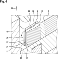
- Fig. 4 shows a perspective detailed view of the outer rotor 6 and a rotary vane 12 of the gerotor pump 1 according to the first embodiment of the present invention. In the Fig. 4 The case back 21 is also shown.
- the rotary valve 12 is clearly positioned on the housing base 21.
- a height 27 of the rotary valve 12 is less than a height 28 of the outer rotor 6 with respect to the axial direction 30.
- the height 27 of the rotary valve 12 is between 90% and 98% of the height 28 of the outer rotor 6.
- fluid indicated by a fluid flow 29, can flow particularly easily from the inlet pump chamber 3 on the rotary valve 12 into the housing space 11 between the outer rotor 6 and the housing 10.
- the aforementioned fluid between the housing cover 20 and the outer rotor 6 and the inner rotor 7 (in the axial gap) can flow particularly easily into the housing space 11, i.e. with low viscous friction.
- the rotary valve 12 also has a rounded side surface 31 on the housing side, which reduces friction between the rotary valve 12 and the housing 10.
- Fig. 5 shows a schematic cross-sectional view of a gerotor pump 1 according to a second embodiment of the present invention.
- the pressure elements are designed as pistons 32.
- the gerotor pump 1 has at least two, in the present case six pistons 32.
- the openings 16 are designed as radial bores in the outer circumference 13 of the outer rotor 6.
- the pistons 32 are radially displaceable and seal a radial housing-side end 34 of the respective opening 16.
- the openings 16 are fluidically connected to the inlet pump chamber 3 and/or to the outlet pump chamber 5.
- This essentially results in an L-shaped bore in the outer rotor 6, with the respective piston 32 being arranged in the radial bore.
- This allows the fluid which is between the housing cover 20 and the outer rotor 6 (in the axial gap) to flow through the axial part of the bores into the openings 6.
- the axial bore is fluidly connected to the axial gap.
- piston pressure chambers 33 are formed between the radial inner side 17 of the opening 16 and the respective pistons 32.
- the pistons 32 are pressed radially into the openings 16, whereby the fluid is pressurized by the piston 32.
- This resulting pressure exerts a force on the radial inner side 17 of the opening 16 and thus on the outer rotor 6, whereby it is positioned against the inner rotor 7.
- the piston pressure chambers 33 are secondary pressure areas, similar to the pressure chambers 14, which are generated by the rotary valves 12.
- the pistons 32 can also create the pressure chambers 14 between the outer rotor 6 and the housing 10 in the housing space 11.
- the pistons 32 can have a corresponding height 27 of the rotary slide valves 12.
- the outer rotor 6 is not arranged centrally in the housing space 11, at least when the pump 1 is at rest.
- the outer rotor 6 can be arranged centrally in the housing space 11 when the pump 1 is at rest.
- a pressure difference between the inlet 2 and the outlet 4 causes the outer rotor 6 to be turned on when the pump 1 is operating.
- This turning particularly at high pressures, also causes the outer rotor 6 to be arranged non-centrally in the housing space 11, so that even in such a case the secondary pressure areas are formed during operation of the pump 1.
- these secondary pressure areas at least partially counteract the turning by the primary pressure areas, so that the gap between the outer rotor 6 and the inner rotor 7 is reduced at least during operation of the pump 1 and its efficiency is increased.
- the Figures 6 and 7 each show schematic sectional views of a gerotor pump 1 according to a third embodiment of the present invention.
- the housing 10 has a plurality, here four, openings 37, also called housing openings 37, along its inner circumference 36.
- a radially displaceable pressure element is arranged as a rotary slide valve 35.
- Each rotary slide valve 35 rests, particularly during operation of the gerotor pump 10, along the circumferential direction 18 on at least one inner surface 41 of the housing 10 or the housing opening 37.
- Each rotary valve 35 protrudes from a radial inner side 39 of the housing opening 37 and is arranged on the outer rotor 6. As can be seen in particular from Fig. 7 It can be seen that each rotary valve 35 is positioned or preloaded against the outer rotor 6 by a spring element 38, here a leaf spring.
- a height 27 of the rotary valve 35 with respect to the axial direction 30 is less than a height 42 of the housing 10.
- the height 27 of the rotary valve 35 is in particular less than a height 28 of the outer rotor 6.
- the housing cover 20 or the housing base 21 can have grooves which guide the fluid into the housing opening 37.
- the spring element 38 can be functionally replaced at least partially by fluid in the housing opening 37, which positions the rotary slide 35 against the outer rotor 6.
- the housing 10 can have one or more housing grooves 43, which in Fig. 6 is shown in dashed lines.
- This housing groove 43 is an axial recess in the housing 10 and connects two openings 37 to one another so that they are fluidically connected to one another.
- the housing groove 43 shown connects the two openings 37 to the housing space 11 so that the openings 37 are fluidically connected to it.
- housing grooves 43 can be arranged in the housing 10.
- two housing grooves 43 can be formed, each of which connects two of the four openings 37 to one another.
- two of the openings 37 can be fluidically connected to the inlet pump chamber 3 and the other two of the openings 37 can be fluidically connected to the outlet pump chamber 5, without these being fluidically short-circuited (in pairs).
- the rotary valves 35 of the present embodiment provide the same advantages as the rotary valves 12 of the first embodiment.
- the rotary valves 35 create pressure chambers 14 in the housing space 11 radially between the outer rotor 6 and the housing 10, whereby the outer rotor 6 is adjusted.
- the gerotor pump 1 according to the present embodiment can be combined with the gerotor pump 1 according to the first and/or the second embodiment.
- the rotary vanes 35 of the present embodiment apart from being arranged in the housing 10, and their associated openings 37 can have similar or identical configurations to the pressure elements 12, 32 and openings 16 of the first two embodiments.
- the present rotary vanes 35 can also be designed as pistons which position the outer rotor 6 against the inner rotor 7.
- This combination can be combined particularly advantageously with the aforementioned configuration in which the housing 10 has one or more housing grooves 43, in addition to or as an alternative to the possible grooves in the housing cover 20 or in the housing base 21.
- the invention also relates to a motor-pump unit 100.
- Fig. 8 shows a schematic block diagram of the motor-pump unit 100 according to an embodiment of the present invention.
- the motor-pump unit 100 comprises a motor 101 and a gerotor pump 1 according to the above embodiments.
- the motor 101 is designed to rotate the inner rotor 7 to operate the gerotor pump 1.
- the motor 101 is connected to the inner rotor 7 by means of a shaft 102 (see also Fig. 2 ) mechanically connected to the inner rotor 7.
- the motor-pump unit 100 has a particularly good efficiency and is more tolerance-independent.
Landscapes
- Engineering & Computer Science (AREA)
- Mechanical Engineering (AREA)
- General Engineering & Computer Science (AREA)
- Rotary Pumps (AREA)
- Details And Applications Of Rotary Liquid Pumps (AREA)
Applications Claiming Priority (1)
| Application Number | Priority Date | Filing Date | Title |
|---|---|---|---|
| DE102023122127.2A DE102023122127A1 (de) | 2023-07-06 | 2023-08-18 | Gerotorpumpe und Motor-Pumpen-Einheit |
Publications (2)
| Publication Number | Publication Date |
|---|---|
| EP4509715A2 true EP4509715A2 (fr) | 2025-02-19 |
| EP4509715A3 EP4509715A3 (fr) | 2025-03-12 |
Family
ID=92208835
Family Applications (1)
| Application Number | Title | Priority Date | Filing Date |
|---|---|---|---|
| EP24191639.4A Pending EP4509715A3 (fr) | 2023-08-18 | 2024-07-30 | Pompe gérotor et unité moteur-pompe |
Country Status (1)
| Country | Link |
|---|---|
| EP (1) | EP4509715A3 (fr) |
Family Cites Families (3)
| Publication number | Priority date | Publication date | Assignee | Title |
|---|---|---|---|---|
| JPS6424188A (en) * | 1987-07-16 | 1989-01-26 | Yoshio Ono | Low deceleration torque reinforcement motor |
| US6053706A (en) * | 1998-03-13 | 2000-04-25 | Engineered Machined Products | Oil pump with integrated oil metering device |
| JP2003027912A (ja) * | 2001-07-13 | 2003-01-29 | Toyoda Spinning & Weaving Co Ltd | 複合ポンプ |
-
2024
- 2024-07-30 EP EP24191639.4A patent/EP4509715A3/fr active Pending
Non-Patent Citations (1)
| Title |
|---|
| JAROSLAW STRYCZEKSLAWOMIR BEDNARCZYK: "aus „the 19th International Conference on Hydraulics and Pneumatics", article "Axial clearance compensation in the gerotor pump" |
Also Published As
| Publication number | Publication date |
|---|---|
| EP4509715A3 (fr) | 2025-03-12 |
Similar Documents
| Publication | Publication Date | Title |
|---|---|---|
| DE69313560T2 (de) | Hydraulische Flügelzellenpumpe mit verbessertem axialen Druckausgleich und verbesserten Druckflusseigenschaften | |
| DE3590198C2 (de) | Ventilplatte für eine hydrostatische Axialkolbeneinheit | |
| DE2939945A1 (de) | Schneckenmaschine mit axial nachgiebiger dichtung | |
| DE102007032103B4 (de) | Pumpeneinheit mit einer Hauptpumpe und einer in ihrem Fördervolumen verstellbaren Ladepumpe | |
| DE3800324A1 (de) | Fluegelzellenverdichter | |
| DE4308506A1 (de) | Ölpumpensystem | |
| DE1653801A1 (de) | Kapselpumpe | |
| EP1495227B1 (fr) | Groupe motopompe hydraulique | |
| DE10353027A1 (de) | Regelbare Pumpe, insbesondere Flügelzellenpumpe | |
| DE102004021216B4 (de) | Hochdruck-Innenzahnradmaschine mit mehrfacher hydrostatischer Lagerung pro Hohlrad | |
| DE1808826A1 (de) | Drehlkolbenmaschine | |
| DE112010001701B4 (de) | Flügelzellenpumpe mit verbessertem Rotor und Drehschiebererweiterungsring | |
| DE102005041579B4 (de) | Innenzahnradpumpe mit Füllstück | |
| EP0509077B1 (fr) | Pompe a pistons, notamment pompe a pistons radiaux | |
| WO1995004221A1 (fr) | Pompe a vide a palette a deux etages | |
| EP4509715A2 (fr) | Pompe gérotor et unité moteur-pompe | |
| DE102023122127A1 (de) | Gerotorpumpe und Motor-Pumpen-Einheit | |
| WO2007039405A1 (fr) | Pompe a palettes | |
| DE3322549A1 (de) | Fluegelzellenpumpe mit veraenderlichem foerderhub fuer hydraulische betriebsmittel insbesondere von kraftfahrzeugen | |
| EP0929743B1 (fr) | Pompe a piston radial | |
| DE3801306A1 (de) | Fluegelzellenverdichter | |
| DE102019110762B4 (de) | Schlitzgesteuerte Radialkolbenpumpe | |
| DE102013224660A1 (de) | Flügelzellenmaschine mit definiertem Druck in den Hinterflügelräumen | |
| WO2009019095A1 (fr) | Pompe cellulaire à aubes à pression réduite sur les aubes | |
| DE3737961A1 (de) | Innenzahnradpumpe |
Legal Events
| Date | Code | Title | Description |
|---|---|---|---|
| PUAI | Public reference made under article 153(3) epc to a published international application that has entered the european phase |
Free format text: ORIGINAL CODE: 0009012 |
|
| STAA | Information on the status of an ep patent application or granted ep patent |
Free format text: STATUS: THE APPLICATION HAS BEEN PUBLISHED |
|
| PUAL | Search report despatched |
Free format text: ORIGINAL CODE: 0009013 |
|
| AK | Designated contracting states |
Kind code of ref document: A2 Designated state(s): AL AT BE BG CH CY CZ DE DK EE ES FI FR GB GR HR HU IE IS IT LI LT LU LV MC ME MK MT NL NO PL PT RO RS SE SI SK SM TR |
|
| AK | Designated contracting states |
Kind code of ref document: A3 Designated state(s): AL AT BE BG CH CY CZ DE DK EE ES FI FR GB GR HR HU IE IS IT LI LT LU LV MC ME MK MT NL NO PL PT RO RS SE SI SK SM TR |
|
| RIC1 | Information provided on ipc code assigned before grant |
Ipc: F04C 11/00 20060101ALI20250205BHEP Ipc: F04C 2/344 20060101ALI20250205BHEP Ipc: F04C 2/10 20060101AFI20250205BHEP |
|
| STAA | Information on the status of an ep patent application or granted ep patent |
Free format text: STATUS: REQUEST FOR EXAMINATION WAS MADE |
|
| 17P | Request for examination filed |
Effective date: 20250912 |