EP4509827A2 - Verfahren und system zur erkennung und/oder überwachung des wachstums von defekten - Google Patents
Verfahren und system zur erkennung und/oder überwachung des wachstums von defekten Download PDFInfo
- Publication number
- EP4509827A2 EP4509827A2 EP24212088.9A EP24212088A EP4509827A2 EP 4509827 A2 EP4509827 A2 EP 4509827A2 EP 24212088 A EP24212088 A EP 24212088A EP 4509827 A2 EP4509827 A2 EP 4509827A2
- Authority
- EP
- European Patent Office
- Prior art keywords
- magnetometers
- values
- reading
- defect
- mfl
- Prior art date
- Legal status (The legal status is an assumption and is not a legal conclusion. Google has not performed a legal analysis and makes no representation as to the accuracy of the status listed.)
- Pending
Links
Images

Classifications
-
- G—PHYSICS
- G01—MEASURING; TESTING
- G01N—INVESTIGATING OR ANALYSING MATERIALS BY DETERMINING THEIR CHEMICAL OR PHYSICAL PROPERTIES
- G01N27/00—Investigating or analysing materials by the use of electric, electrochemical, or magnetic means
- G01N27/72—Investigating or analysing materials by the use of electric, electrochemical, or magnetic means by investigating magnetic variables
- G01N27/82—Investigating or analysing materials by the use of electric, electrochemical, or magnetic means by investigating magnetic variables for investigating the presence of flaws
- G01N27/83—Investigating or analysing materials by the use of electric, electrochemical, or magnetic means by investigating magnetic variables for investigating the presence of flaws by investigating stray magnetic fields
- G01N27/87—Investigating or analysing materials by the use of electric, electrochemical, or magnetic means by investigating magnetic variables for investigating the presence of flaws by investigating stray magnetic fields using probes
-
- G—PHYSICS
- G01—MEASURING; TESTING
- G01N—INVESTIGATING OR ANALYSING MATERIALS BY DETERMINING THEIR CHEMICAL OR PHYSICAL PROPERTIES
- G01N27/00—Investigating or analysing materials by the use of electric, electrochemical, or magnetic means
- G01N27/72—Investigating or analysing materials by the use of electric, electrochemical, or magnetic means by investigating magnetic variables
- G01N27/82—Investigating or analysing materials by the use of electric, electrochemical, or magnetic means by investigating magnetic variables for investigating the presence of flaws
Definitions
- the invention relates to a method of and a system for detecting and/or monitoring the forming and/or the growth of defects, in particular cracks or plastic deformation, and/or suspected defects in ferromagnetic structures, such as civil engineering and marine structures, comprising reading values of magnetic flux leakage (MFL) from a plurality of magnetometers, placed over or near a defect or a suspected defect, and storing the values of magnetic flux leakage (MFL), typically in a memory that is part of and/or accessible via a controller or computer.
- MFL magnetic flux leakage
- Non-destructive evaluation is widely used to inspect objects, such as ships, offshore structures, renewable energy devices, e.g. windmills, bridges, buildings, cranes, railway, cars, machinery, and pipelines, for defects and damage due to corrosion and wear. Defects include cracks, inclusions, lack of fusion, incomplete penetration and porosities.
- One of the NDE methods is based on the so-called magnetic flux leakage (MFL) in the vicinity of a defect.
- MFL magnetic particle inspection
- the envisaged crack monitoring system would consist of arrays of Hall effect sensors that are placed on detected cracks, so that their propagation can be monitored without additional inspections.
- the Hall effect sensors need to be placed at an optimal altitude above the metal surface, balancing between the sensor sensitivity and accompanied costs, and the spatial density of sensors required for accurate crack length characterization.
- a crack can be monitored as long as it is underneath the sensor array.
- crack length dependency of the SMFL creates opportunities to estimate the crack length even when it has propagated outside the sensor array.”
- the method according to the invention is characterized by reading values of magnetic flux leakage (MFL) from a plurality of magnetometers at a further (later) point in time,
- the reading of values typically contains little or insufficient information at least in that it does not provide an accurate location of a singular point, such as the tip of a crack, at which the defect propagates or forms. It was found that processing the values of MFL of a current reading with the values of MFL of an earlier reading, such as an initial or reference reading or the preceding reading, significantly improves the accuracy of the data relating to the location of a singular point, in particular the tip of the crack, in the current reading and in many cases even enables locating the singular point where this was impossible with existing methods.
- Defects can be surface breaking defects, also known as surface defects or surface flaws, and/or non-surface breaking defects, also known as subsurface defects or embedded flaws.
- defects include cracks, plastic deformation (which often is an indication or a precursor of a crack), corrosion, and pitting.
- Suspected defects include indications that a defect is present and include likely or expected defects, such as critical locations in structures that could contain a defect or where a defect is likely to form or originate.
- the system comprises at least 3 magnetometers, preferably at least 5 magnetometers, preferably at least 10 magnetometers, preferably at least 20 magnetometers, and/or that the magnetometers are arranged in an array (two dimensions) or in a (single) line (one dimension parallel to the surface on which the magnetometers are placed), in particular a straight line and/or that the distance between most, preferably all, of the magnetometers is equal.
- the frequency of the reading of values depends on the circumstances, e.g. the expected rate of propagation or the nature of the structure, i.e. a higher expected rate and more critical structures could necessitate more frequent readings. In general, more frequent readings, e.g. one or more readings per day or per hour, generate more data and are generally preferred. As batteries improve, a higher frequencies will be simpler to implement. With low expected rates and/or non-critical structures readings can be less frequent, e.g. weekly, monthly, or even quarterly.
- the magnetometers are placed over the (suspected) defect or near the (suspected) defect, e.g. less than 200 mm, preferably less than 100 mm, preferably less than 50, e.g. within 10 mm from the (suspected) defect.
- the values comprise data of MFL in two or more directions, preferably at least in a direction along the defect (provided of course that the direction can be determined) and in a direction perpendicular to the surface of the ferromagnetic structure on which the magnetometers are placed.
- the method comprises the steps of comparing sets of values of MFL in different directions, selecting at least one set, and determining the location of a singular point of the (suspected) defect from the selected set.
- At least one signal i.e. set of values read/measured with a plurality of magnetometers in a particular direction, e.g. along the defect, will typically provide a clearer change in sign, in particular from positive to negative, or direction (peak) than the other(s). This signal is then selected to determine the location of a singular point.
- the combination of reading values in two or more, e.g. three directions, and arranging the magnetometers in a single dimension, such as a line, in particular a straight line, provides a relatively compact yet effective means for detecting and/or monitoring the forming and/or the growth of defects, in particular cracks or plastic deformation.
- the values of magnetic flux leakage are read passively, in particular without actively generating a magnetic field and preferably by reading only permanent magnetisation, stress induced magnetisation (also known as the magnetoelastic or Villari effect) and/or the Earth magnetic field, which is/are naturally available as a source or origin of magnetism.
- processing the values of the further reading with the values from the earlier reading involves at least one of calculating, preferably for individual magnetometers, preferably for each of the magnetometers individually, a (weighted) moving average of readings at different points in time, a derivative, a difference, a (weighted) mean squared error, a (weighted) least squares error, zero-crossing or similar noise filtering, and signal reduction processing steps, of such readings.
- values from the earlier reading are subtracted from the values of the further reading.
- the invention also relates to a system for detecting and/or monitoring the growth of defects, in particular cracks, in ferromagnetic structures, such as civil engineering and marine structures, comprising a plurality of magnetometers and means, such as a controller, for carrying out the method described above.
- the system comprises at least 3 magnetometers, at least 5 magnetometers, preferably at least 10 magnetometers, preferably at least 20 magnetometers, and/or wherein the magnetometers are arranged in an array or in a line, in particular a straight line, or in parallel (straight) lines and/or wherein the distance between most, preferably all, of the magnetometers is equal.
- magnetometers configured to measure magnetism based on Hall effect, on anisotropic magnetoresistance (AMR), or on fluxgate. It is preferred that the magnetometers measure magnetism in at least two directions, preferably in three directions.
- Another embodiment comprises a controller connected to the magnetometers and configured to turn the magnetometers on, i.e. activate the magnetometers, initiate the readings/measurements, and turn the magnetometers off, preferably periodically.
- the system comprises a battery and/or an energy generating and/or harvesting device.
- the controller comprises a processor, a memory, e.g. an (E)EPROM on a printed circuit board, that is accessible via the controller.
- a processor e.g. an (E)EPROM on a printed circuit board, that is accessible via the controller.
- a memory e.g. an (E)EPROM on a printed circuit board
- the system comprises a transmitter to send data read with the magnetometers to a receiver and wherein the transmitter preferably is based on the Global System for Mobile Communications (GSM), Long Range Low Power (LoRa), Wifi, and other Radio Frequency standards.
- GSM Global System for Mobile Communications
- LiRa Long Range Low Power
- Wifi Wireless Fidelity
- the magnetometers are accommodated in a housing and/or embedded in a surrounding material, which housing and/or embedding is water and/or oil resistant or weather-, water- and/or oilproof.
- the controller and/or the transmitter are accommodated in a separate housing, and the controller is connected to the magnetometers, wired or wirelessly.
- the senor comprises an adhesive layer, e.g. in the form of adhesive tape or a coating, mechanical fasteners and/or one or more magnets to mount the sensor on a metal structure.
- an adhesive layer e.g. in the form of adhesive tape or a coating, mechanical fasteners and/or one or more magnets to mount the sensor on a metal structure.
- the invention also relates to a computer program comprising instructions to cause the system described above to execute the steps of the method described above and to a computer-readable medium having the computer program stored thereon.
- US 2015/377012 relates to a methodology and system for anomaly recognition and tracking in a variety of components, such as tubular components.
- the technique comprises sensing for anomalies in the component, and storing detected anomalies in a storage medium.
- the detected anomalies are matched with stored digital descriptions of anomalies.
- the stored digital descriptions may comprise anomalies of similar types and/or anomalies previously detected on the specific component being tested.
- the detected anomalies are ranked according to similarities with respect to the stored digital descriptions.
- US 2018/038833 concerns a method and a system to create and use pre-magnetized ferromagnetic structures, where magnetic field direction rotates with depth, and analyze the nature of defects in the structures.
- US 2014/368191 discloses a device for discovering, identification and monitoring, of mechanical flaws in metallic structures, based on magneto-graphic/magnetic tomography technique to identify stress-related defects.
- US 2017/176389 relates to a method for identifying and locating a defect in a metal rail, which method includes the steps of positioning a first magnetic sensor at a distance above a rail, the first magnetic sensor being configured to measure a magnetic field of the rail; advancing the sensor along a length of the rail; sampling magnetic field measurements; determining multiple magnetic field gradients over different pluralities of samples; identifying a defect in the rail based on a change in one or more of the magnetic field gradients; and determining a position of the defect at a particular distance from the magnetic sensor based on a degree of variation in the magnetic field gradients.
- defects in ferromagnetic materials are detected and characterized by analyzing the items' magnetic fields to find portions of the magnetic fields that differ in characteristic ways from residual magnetic fields generated by non-defective portions of the items.
- the portions of the magnetic fields that differ in the characteristic ways correspond to locations of the defects.
- the residual magnetic fields correspond to portions of the items distant from the defects.
- the defect characterization may include volume of material lost due to each defect and/or width and/or depth of each defect.
- US 2017/108469 relates to a system and method using magnetic sensing to non-intrusively and non-destructively characterize ferromagnetic material within infrastructure.
- the system includes sensors for measuring magnetic field gradients from a standoff distance adjacent to ferromagnetic material.
- the method includes using the system to measure magnetic fields, determining magnetic field gradients measured by a sensor array, and comparing measured and modeled or historical magnetic field gradients at the same or similar positions to identify differences caused by a phenomenon in the ferromagnetic material, and, in a particular embodiment, to recognize defects and developing defects.
- Figure 1 schematically shows a system 1 for detecting and monitoring the growth of defects in accordance with the present invention, comprising a plurality of sensor strips 2 to be placed over or near a (suspected) defect and a control unit 3 for operating and communicating with the sensor strips.
- Each strip comprises a plurality of triaxial Hall effect magnetometers 4, preferably at least 3, preferably arranged in a line, in particular a straight line, and has an adhesive surface to attach the strip to a steel structure, such as a civil engineering and marine structure.
- control unit 3 comprises a battery pack 5, a permanent magnet 6 to attach the control unit to the steel structure, a controller-board and processor 7, such as a plc, a microcontroller, or a single board computer, connector ports 8 for cables 9 connecting the sensor strips to the control unit, and a radio frequency (RF) module 10 to communicate with a central computer (not shown).
- a controller-board and processor 7 such as a plc, a microcontroller, or a single board computer
- connector ports 8 for cables 9 connecting the sensor strips to the control unit and a radio frequency (RF) module 10 to communicate with a central computer (not shown).
- RF radio frequency
- the controller is configured to turn the magnetometers on, i.e. activate the magnetometers, read values of magnetic flux leakage (MFL) from the plurality of magnetometers in three directions, and turn the magnetometers off.
- the transmitter is configured to send data read with the magnetometers to a receiver connected to the central computer, e.g. via GSM, LoRa, Wii, or another Radio Frequency standard.
- Figure 2 shows a sensor 2 for carrying out MFL measurements, having 30 triaxial Hall effect magnetometers 4 arranged in a straight line at a consistent center to center separation of 3.2 mm.
- the strip is adhered to a steel structure 11 alongside and essentially parallel to an existing surface breaking crack 12 having a clearly visible singular point, i.c. the tip 13 of the crack 12.
- the sensor in Figure 2 was used to carry out a first reading of values of MFL in three directions, in this example
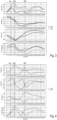
- the individual readings shown in Figure 3 contain no or at least insufficient information to accurately located of the tip of the crack.
- Figure 4 shows values of magnetic flux leakage (MFL) from the second and third readings processed with the reading of the first and second readings, respectively.
- MFL magnetic flux leakage
- the position of these sensors corresponded accurately to the actual location of the tip of the crack at the time of the second reading (AUG) and the third reading (SEP), respectively.
- Benefits of defect detection and a defect monitoring system based on such measurements are e.g. that the risk level of measured objects can be assessed, that rational decision making on defect repair can be made, and that less frequent inspections can be made by surveyors what translates into less injuries/accidents, and/or significantly reduced costs.
- the senor can be employed to detect new cracks, e.g. by placing sensors on locations where cracks are relatively likely to form.
- the invention relates to a method as defined in the following clauses:
Landscapes
- Chemical & Material Sciences (AREA)
- Chemical Kinetics & Catalysis (AREA)
- Electrochemistry (AREA)
- Physics & Mathematics (AREA)
- Health & Medical Sciences (AREA)
- Life Sciences & Earth Sciences (AREA)
- Analytical Chemistry (AREA)
- Biochemistry (AREA)
- General Health & Medical Sciences (AREA)
- General Physics & Mathematics (AREA)
- Immunology (AREA)
- Pathology (AREA)
- Investigating Or Analyzing Materials By The Use Of Magnetic Means (AREA)
Applications Claiming Priority (3)
| Application Number | Priority Date | Filing Date | Title |
|---|---|---|---|
| EP21167728 | 2021-04-09 | ||
| EP22722174.4A EP4189379B1 (de) | 2021-04-09 | 2022-04-08 | Verfahren und system zur erkennung und/oder überwachung des wachstums von defekten |
| PCT/EP2022/059537 WO2022214694A1 (en) | 2021-04-09 | 2022-04-08 | Method of and system for detecting and/or monitoring the growth of defects |
Related Parent Applications (1)
| Application Number | Title | Priority Date | Filing Date |
|---|---|---|---|
| EP22722174.4A Division EP4189379B1 (de) | 2021-04-09 | 2022-04-08 | Verfahren und system zur erkennung und/oder überwachung des wachstums von defekten |
Publications (2)
| Publication Number | Publication Date |
|---|---|
| EP4509827A2 true EP4509827A2 (de) | 2025-02-19 |
| EP4509827A3 EP4509827A3 (de) | 2025-04-30 |
Family
ID=75441848
Family Applications (2)
| Application Number | Title | Priority Date | Filing Date |
|---|---|---|---|
| EP22722174.4A Active EP4189379B1 (de) | 2021-04-09 | 2022-04-08 | Verfahren und system zur erkennung und/oder überwachung des wachstums von defekten |
| EP24212088.9A Pending EP4509827A3 (de) | 2021-04-09 | 2022-04-08 | Verfahren und system zur erkennung und/oder überwachung des wachstums von defekten |
Family Applications Before (1)
| Application Number | Title | Priority Date | Filing Date |
|---|---|---|---|
| EP22722174.4A Active EP4189379B1 (de) | 2021-04-09 | 2022-04-08 | Verfahren und system zur erkennung und/oder überwachung des wachstums von defekten |
Country Status (6)
| Country | Link |
|---|---|
| US (1) | US20240192170A1 (de) |
| EP (2) | EP4189379B1 (de) |
| CN (1) | CN117460952A (de) |
| BR (1) | BR112023020850A2 (de) |
| ES (1) | ES3009470T3 (de) |
| WO (1) | WO2022214694A1 (de) |
Families Citing this family (2)
| Publication number | Priority date | Publication date | Assignee | Title |
|---|---|---|---|---|
| CN118425287B (zh) * | 2024-04-29 | 2025-04-15 | 无锡学院 | 一种基于均匀平行感应电流流动特性的缺陷轮廓识别方法 |
| CN119738523B (zh) * | 2024-11-26 | 2025-09-26 | 中兴华骏建设有限公司 | 一种土木结构的裂纹检测装置 |
Citations (6)
| Publication number | Priority date | Publication date | Assignee | Title |
|---|---|---|---|---|
| US20140368191A1 (en) | 2012-11-12 | 2014-12-18 | Valerian Goroshevskiy | Apparatus and method for metallic constructions assessment |
| US20150330946A1 (en) | 2014-05-18 | 2015-11-19 | The Charles Stark Draper Laboratory, Inc. | System and Method of Measuring Defects in Ferromagnetic Materials |
| US20150377012A1 (en) | 2014-06-27 | 2015-12-31 | Schlumberger Technology Corporation | Anomaly Recognition System And Methodology |
| US20170108469A1 (en) | 2015-06-29 | 2017-04-20 | The Charles Stark Draper Laboratory, Inc. | System and method for characterizing ferromagnetic material |
| US20170176389A1 (en) | 2014-02-11 | 2017-06-22 | Pure Technologies Ltd. | Method and system for non-destructive rail inspection |
| US20180038833A1 (en) | 2016-08-08 | 2018-02-08 | The Charles Stark Draper Laboratory, Inc. | Method for Determining Defect Depth in Ferromagnetic Structures Based on Magnetic Flux Leakage Direction |
Family Cites Families (7)
| Publication number | Priority date | Publication date | Assignee | Title |
|---|---|---|---|---|
| US4449408A (en) * | 1982-04-22 | 1984-05-22 | Magnetic Analysis Corporation | EMAT Test apparatus having retractable probe |
| MX2008001357A (es) * | 2005-07-29 | 2008-04-16 | V&M Deutschland Gmbh | Metodo para la prueba no destructiva de defectos de superficie en tubos. |
| CN101995432A (zh) * | 2010-11-04 | 2011-03-30 | 重庆大学 | 基于霍尔元件差分阵列的铁磁构件表面裂纹探测器 |
| CN113348755B (zh) * | 2015-10-30 | 2018-12-07 | 中国人民解放军陆军工程大学 | 基于磁梯度张量的金属磁记忆缺陷定位方法 |
| US10767383B2 (en) * | 2017-11-07 | 2020-09-08 | Robin Technologies, Inc. | Ground wire guidance system for robotic vehicle with doorway access |
| US20200132783A1 (en) * | 2018-10-30 | 2020-04-30 | Qualcomm Incorporated | Opportunistic magnetometer calibration |
| EP3859325A1 (de) * | 2020-02-03 | 2021-08-04 | INGU Solutions Inc. | System, verfahren und vorrichtung zur inspektion von fluidleitungen |
-
2022
- 2022-04-08 CN CN202280041316.8A patent/CN117460952A/zh active Pending
- 2022-04-08 BR BR112023020850A patent/BR112023020850A2/pt unknown
- 2022-04-08 EP EP22722174.4A patent/EP4189379B1/de active Active
- 2022-04-08 WO PCT/EP2022/059537 patent/WO2022214694A1/en not_active Ceased
- 2022-04-08 EP EP24212088.9A patent/EP4509827A3/de active Pending
- 2022-04-08 ES ES22722174T patent/ES3009470T3/es active Active
- 2022-04-08 US US18/554,434 patent/US20240192170A1/en active Pending
Patent Citations (6)
| Publication number | Priority date | Publication date | Assignee | Title |
|---|---|---|---|---|
| US20140368191A1 (en) | 2012-11-12 | 2014-12-18 | Valerian Goroshevskiy | Apparatus and method for metallic constructions assessment |
| US20170176389A1 (en) | 2014-02-11 | 2017-06-22 | Pure Technologies Ltd. | Method and system for non-destructive rail inspection |
| US20150330946A1 (en) | 2014-05-18 | 2015-11-19 | The Charles Stark Draper Laboratory, Inc. | System and Method of Measuring Defects in Ferromagnetic Materials |
| US20150377012A1 (en) | 2014-06-27 | 2015-12-31 | Schlumberger Technology Corporation | Anomaly Recognition System And Methodology |
| US20170108469A1 (en) | 2015-06-29 | 2017-04-20 | The Charles Stark Draper Laboratory, Inc. | System and method for characterizing ferromagnetic material |
| US20180038833A1 (en) | 2016-08-08 | 2018-02-08 | The Charles Stark Draper Laboratory, Inc. | Method for Determining Defect Depth in Ferromagnetic Structures Based on Magnetic Flux Leakage Direction |
Also Published As
| Publication number | Publication date |
|---|---|
| BR112023020850A2 (pt) | 2023-12-12 |
| ES3009470T3 (en) | 2025-03-27 |
| US20240192170A1 (en) | 2024-06-13 |
| CN117460952A (zh) | 2024-01-26 |
| WO2022214694A1 (en) | 2022-10-13 |
| EP4189379A1 (de) | 2023-06-07 |
| EP4509827A3 (de) | 2025-04-30 |
| EP4189379B1 (de) | 2024-11-13 |
| EP4189379C0 (de) | 2024-11-13 |
Similar Documents
| Publication | Publication Date | Title |
|---|---|---|
| Zhao et al. | Uniaxial ACFM detection system for metal crack size estimation using magnetic signature waveform analysis | |
| EP2808677B1 (de) | Verfahren zum berührungslosen Prüfen von metallischen Konstruktionen | |
| RU2264617C2 (ru) | Способ бесконтактного выявления местоположения и характера дефектов металлических сооружений и устройство для его осуществления | |
| AU2013227428B2 (en) | Fault detection for pipelines | |
| AU2013227426B2 (en) | Fault detection for pipelines | |
| Usarek et al. | Inspection of gas pipelines using magnetic flux leakage technology | |
| CN103499404A (zh) | 铁磁构件交变应力测量装置及其测量方法 | |
| EP4189379B1 (de) | Verfahren und system zur erkennung und/oder überwachung des wachstums von defekten | |
| RU2630856C1 (ru) | Способ диагностики технического состояния подземных трубопроводов | |
| CN103196991A (zh) | 连续诊断管体金属腐蚀与缺陷的全覆盖瞬变电磁检测方法 | |
| CN113138421A (zh) | 一种埋地金属管道埋深及走向检测方法 | |
| EP3344982B1 (de) | Verfahren und system zur erkennung einer materialdiskontinuität bei einem magnetisierbaren artikel | |
| RU2724582C1 (ru) | Способ бесконтактного выявления наличия, месторасположения и степени опасности концентраторов механических напряжений в металле ферромагнитных сооружений | |
| US20210072187A1 (en) | Non-destructive inspection device | |
| US20250189488A1 (en) | Deep electromagnetic rebar probe system, and method of using same | |
| CN113050182B (zh) | 一种水域地磁场观测方法及系统 | |
| Zhang et al. | Alternating current field measurement probe for coiled tubing inspection of arbitrary direction defects | |
| Jian et al. | Lightweight, high performance detection method of pipeline defects through compact off-axis magnetization and sensing | |
| Witoś et al. | NDE of mining ropes and conveyors using magnetic methods | |
| EP3910327A1 (de) | Sensor zur detektion und/oder überwachung des wachstums von defekten | |
| Mosharafi | Improving passive magnetic inspection for reinforced concrete condition assessment | |
| Sathappan | Magnetic Flux Leakage techniques for detecting corrosion of pipes | |
| CN111175836A (zh) | 管道载体雷达损伤检测工艺 | |
| Ramos et al. | Determination of linear defect depths from eddy currents disturbances | |
| CN211698233U (zh) | 管道载体雷达损伤检测系统 |
Legal Events
| Date | Code | Title | Description |
|---|---|---|---|
| PUAI | Public reference made under article 153(3) epc to a published international application that has entered the european phase |
Free format text: ORIGINAL CODE: 0009012 |
|
| STAA | Information on the status of an ep patent application or granted ep patent |
Free format text: STATUS: THE APPLICATION HAS BEEN PUBLISHED |
|
| AC | Divisional application: reference to earlier application |
Ref document number: 4189379 Country of ref document: EP Kind code of ref document: P |
|
| AK | Designated contracting states |
Kind code of ref document: A2 Designated state(s): AL AT BE BG CH CY CZ DE DK EE ES FI FR GB GR HR HU IE IS IT LI LT LU LV MC MK MT NL NO PL PT RO RS SE SI SK SM TR |
|
| PUAL | Search report despatched |
Free format text: ORIGINAL CODE: 0009013 |
|
| AK | Designated contracting states |
Kind code of ref document: A3 Designated state(s): AL AT BE BG CH CY CZ DE DK EE ES FI FR GB GR HR HU IE IS IT LI LT LU LV MC MK MT NL NO PL PT RO RS SE SI SK SM TR |
|
| RIC1 | Information provided on ipc code assigned before grant |
Ipc: G01N 27/87 20060101AFI20250325BHEP |
|
| RAP3 | Party data changed (applicant data changed or rights of an application transferred) |
Owner name: VILLARI HOLDING B.V. |
|
| STAA | Information on the status of an ep patent application or granted ep patent |
Free format text: STATUS: REQUEST FOR EXAMINATION WAS MADE |
|
| 17P | Request for examination filed |
Effective date: 20251030 |
|
| STAA | Information on the status of an ep patent application or granted ep patent |
Free format text: STATUS: EXAMINATION IS IN PROGRESS |