EP4509980A2 - Circuit intégré photonique et procédé - Google Patents
Circuit intégré photonique et procédé Download PDFInfo
- Publication number
- EP4509980A2 EP4509980A2 EP24215117.3A EP24215117A EP4509980A2 EP 4509980 A2 EP4509980 A2 EP 4509980A2 EP 24215117 A EP24215117 A EP 24215117A EP 4509980 A2 EP4509980 A2 EP 4509980A2
- Authority
- EP
- European Patent Office
- Prior art keywords
- light
- intensity
- light source
- magnitude
- output
- Prior art date
- Legal status (The legal status is an assumption and is not a legal conclusion. Google has not performed a legal analysis and makes no representation as to the accuracy of the status listed.)
- Granted
Links
Images


Classifications
-
- G—PHYSICS
- G06—COMPUTING OR CALCULATING; COUNTING
- G06F—ELECTRIC DIGITAL DATA PROCESSING
- G06F7/00—Methods or arrangements for processing data by operating upon the order or content of the data handled
- G06F7/58—Random or pseudo-random number generators
- G06F7/588—Random number generators, i.e. based on natural stochastic processes
-
- G—PHYSICS
- G02—OPTICS
- G02B—OPTICAL ELEMENTS, SYSTEMS OR APPARATUS
- G02B6/00—Light guides; Structural details of arrangements comprising light guides and other optical elements, e.g. couplings
- G02B6/24—Coupling light guides
- G02B6/42—Coupling light guides with opto-electronic elements
- G02B6/4201—Packages, e.g. shape, construction, internal or external details
- G02B6/4204—Packages, e.g. shape, construction, internal or external details the coupling comprising intermediate optical elements, e.g. lenses, holograms
- G02B6/4206—Optical features
-
- G—PHYSICS
- G02—OPTICS
- G02B—OPTICAL ELEMENTS, SYSTEMS OR APPARATUS
- G02B6/00—Light guides; Structural details of arrangements comprising light guides and other optical elements, e.g. couplings
- G02B6/24—Coupling light guides
- G02B6/42—Coupling light guides with opto-electronic elements
- G02B6/4298—Coupling light guides with opto-electronic elements coupling with non-coherent light sources and/or radiation detectors, e.g. lamps, incandescent bulbs, scintillation chambers
Definitions
- Random number generators are known which are based on the inherently random behaviour of photons caused by quantum mechanics effects. For example, behaviour of a single photon can be determined and used to generate a truly random number.
- Examples described herein relate to a photonic integrated circuit (PIC) for use in generating a random number, based on the behaviour of photons according to quantum mechanics effects.
- the PIC can be considered a monolithic PIC.
- the substrate is for example a compound of elements from groups III and V of the Periodic Table, for example a so-called III-V semiconductor compound such as Indium Phosphide (InP).
- InP Indium Phosphide
- Such a PIC can be fully contained without optical input or output and is sufficiently compact that it can be integrated in devices such as computers and smart phones. Indeed, such a PIC is more compact, and more simple in construction and operation than known random number generators.
- the PIC is of or less than 100 microns x 1000 - 4000 microns x 4000 microns.
- Fig. 1 illustrates schematically a system of examples for generating a random number, implemented at least in part as a PIC on a common substrate which is for example of a III-V semiconductor compound such as InP.
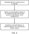
- Fig. 4 illustrates a flow diagram of a method for generating a random number.
- the PIC for use in generating the random number comprises a light source 2 on the substrate (illustrated later with Fig. 3 ), a light detector 4 on the substrate, and a light guidance system 6 on the substrate and configured to direct light from the light source to the light detector.
- Waveguides 8 (illustrated schematically as arrows) of the light guidance system guide light from the light source to the light detector 4.
- Light from the light source when incident on, in other words received by, the light detector 4 causes the light detector to output an electrical signal for use in generating the random number This is explained in further detail later.
- the light source is for example a semiconductor optical amplifier (SOA) or a laser.
- the light detector in other words a photodetector, is for example a photodiode capable of detecting a low light intensity.
- a photon detector is simpler than in known examples referred to as 'single-photon detectors' which use more complex or design limiting detectors such as a silicon photomultiplier (SiPM) avalanche photodiode.
- the photodiode in examples is a monolithically integrated photodiode with a sampling rate of at least giga-Hertz (GHz) frequencies; this offers quicker operation, and hence quicker generation of random numbers, than photodetectors in known systems. Plus, such photodiodes with such GHz or higher sampling rates can detect larger magnitude photocurrents than known photodetectors, which overcomes background electronic noise even more so that quantum effects related fluctuations dominate even more.
- GHz giga-Hertz
- the attenuation system is configured to attenuate an intensity of light output from the light source to an intensity used by the light detector 4 for use in generating a random number. Hence, between the light source and the light detector 4, the attenuation system reduces the intensity of light.
- the attenuation system comprises one or more light splitters 10 such as passive light splitters on the common substrate.
- FIG. 1 shows two such light splitters, but this is schematic; a first light splitter 10a receives light from the light source before other of the light splitters, such as a second light splitter 10b, receives light from the light source (via the first light splitter).
- Fig. 1 is schematic in that although first and second light splitters are shown, in some other examples there may be only one such light splitter, and in other examples there may be more than two light splitters, as required to reduce the light intensity to a level suitable for the light detector 4 (and the overall system set up) to be used in generating a random number.
- a suitable level is sufficiently low such that any fluctuations in the light intensity detected by the light detector 4 are dominated by quantum effects, and hence are in accordance with Poisson statistics. Otherwise, for a higher intensity, and hence a larger number of photons detected per sample by the light detector, any fluctuations caused by quantum effects would be masked, and hence too negligible, relative to the total number of photons detected per sample, to be satisfactorily detectable and used for random number generation.
- the skilled person is familiar with Poisson statistics and hence the Poisson probability distribution which describes the probability of a number of events occurring in a given time period, with the events occurring at a known constant mean rate and which are independent of the time since the last event. Application of the Poisson distribution in generating a random number is explained further below.
- the standard deviation, or inherent fluctuation, of the Poissonian distribution is the square root of the mean sample size. Therefore, the variation relative to the mean sample size decreases with more photon counts per sample.
- low photon counts, especially single photon counting requires optimised photo diodes and electronics.
- An InP PIC features a high sample-rate and low electronic background noise of the photodiode. Therefore, at photon counts of 1000 photons per sample, the inherent quantum fluctuation is still well above (at least ⁇ 10x) the electronic background current. At a high sample rate these 1000 photons per sample will still generate an appreciable photodiode current that can be measured with conventional readout electronics.
- the light source, light detectors and light splitters of the light attenuation system are optically connected to each other, as appropriate, by the light guidance system such as waveguides 8.
- the light guidance system such as waveguides 8.
- an input of the first light splitter is optically connected by a waveguide to receive light from the light source, in some examples directly, and an output of the first light splitter is optically connected by a waveguide to either an input of a subsequent light splitter, or to a light detector.
- Each splitter may be considered to guide or redirect portions of the light from the input to the outputs of the splitter, but as the function of the splitter is to reduce the intensity of light propagating from the light source, the splitters are described herein as part of the light attenuation system.
- the light attenuation system in some examples is configured to, between the light source and the light detector 4, attenuate the intensity of light from the light source by a factor of at least 1000. So, for example light incident on the light detector 4 has an intensity of at most 0.1% of that output by the light source.
- Each light splitter splits light originating from the light source into a first portion of light for propagation to the light detector 4 by the light guidance system, and into a second portion of light which is not guided to the light detector 4.
- a plurality of light splitters may be arranged in series with each other, such that the first portion of light output from one light splitter is guided onwards to be input to the next light splitter in the series, which in turn outputs its first portion of light to be guided onwards to any subsequent light splitters in the series, in turn, until reaching the light detector 4.
- Each light splitter of the attenuation system is for example a light filter, and is for example a multimode interferometer (MMI) which the skilled person is familiar with.
- MMI multimode interferometer
- the waveguide width is increased to transition the light from single mode propagation to multimode propagation.
- the spatial distribution of the optical modes changes as a function of the MMI length, and the appropriate distribution required for a particular splitter's application can be calculated using numerical computation.
- 2 waveguides are fabricated at the length from the start of the MMI where two modes have formed and are spatially well separated.
- each splitter reduces the light intensity in some examples by 50% (such that the first portion of light is 50% and the second portion of light is 50% the intensity of light input to the splitter), and in other examples each splitter reduces the light intensity by 70% (such that the first portion of light is 30% and the second portion of light is 70% the intensity of light input to the splitter).
- 50% such that the first portion of light is 50% and the second portion of light is 50% the intensity of light input to the splitter
- each splitter reduces the light intensity by 70% (such that the first portion of light is 30% and the second portion of light is 70% the intensity of light input to the splitter).
- 50:50 splitters are used in series in some examples, to reduce the intensity for the light detector 4
- six so-called 30:70 splitters are used in series in other examples to reduce the intensity for the light detector 4.
- different splitting ratios are envisaged.
- An MMI is an example of a passive light splitter which does not require driving by a voltage in order to function (as would be the case for an active component).
- Using passive light splitters in the light attenuation system means that a higher power can be used for the light source, which in turn can reduce the need for, and/or the power requirements of, circuitry for driving active components elsewhere in the PIC. Plus, as will be explained further below, such a passive light splitter means that the intensity of light output by the light source can be monitored, which in turn can assist calibration and tuning of the system for generating the random number.
- the light detector 4 described so far is also referred to herein as a first light detector.
- Each second light detector is of the same type of photodiode as the first light detector, but in other examples may be a different type.
- the first light detector is a balanced photodiode or another type of optimised high-accuracy photodiode; the second light detector may be the same or a different type of light detector.
- the PIC comprises first circuitry for processing an electrical signal output by each of the one or more second light detectors.
- a second light detector is for example used to monitor the intensity of light output by the light source. If the second light detector detects a deviation from a target intensity, which indicates that the intensity of light in the first portion guided onwards to the light detector has also deviated, appropriate action can be taken.
- the first circuitry receives the electrical signal from the respective second light detector.
- a property e.g. electrical current
- a property e.g. electrical current
- the first circuitry can cause an appropriate response to maintain the system's ability to generate a random number.
- Such a response may be to adjust a current applied to the light source, to adjust the intensity of light output by the light source. In this way, if the intensity of the second portion is less than the target intensity, the current can be increased to increase the intensity of light output by the light source, to reduce a difference between the actual intensity and the target intensity.
- such a response can be to calibrate a process (described further below) for generating the random number, by adjusting at least one of a threshold value, or a magnitude of a property (e.g. electrical current) measured from the electrical signal output by the first light detector 4, to compensate for any deviation in light intensity from the light source. Otherwise, such a deviation may cause the system to fail, in that any supposedly random number generated is not in fact truly random.
- Such monitoring is performed at least by the second light detector which receives the second portion of light from the first light splitter in the series, and in some examples more than one of the second portion of light from a light splitter in the series is used to monitor the attenuation.
- the second portion of light from each light splitter is output respectively to a different second light detector, so that each attenuation step by a splitter is monitored, and any deviation from a target intensity adjusted for in the current applied to the light source and/or in the processing of the electrical signal output by the first light detector 4.
- the PIC comprises second circuitry configured to use the electrical signal output by the first photodetector 4 for generating a random number.
- the second circuitry receives the electrical signal output by the light detector 4 and determines, based on a property (e.g. electrical current) of the electrical signal a value for use in generating the random number.
- a property e.g. electrical current
- Such a value is in these examples a binary value, otherwise known as a bit, with a value of either 1 or 0.
- a string of binary values may be generated based on a series of measurements of the electrical current; one binary value per measurement.
- the property of the electrical signal measured varies, or fluctuates, over a period of time, caused by quantum effects affecting the passage of photons from the light source to the first light detector 4.
- Various methods are envisaged to use the fluctuations in the property of the electrical signal output by the first light detector 4 in generating a random number.
- the measurements fit the Poisson distribution.
- each measurement of the property of the electrical signal can be compared against the Poisson distribution, or a parameter derived therefrom, to determine the value (e.g. a 1 or a 0) yielded for each measurement, for generating the random number.
- Fig. 2a shows an example plot of many electrical current measurements of the electrical signal output by a light detector 4.
- the plot assumes 1000 photons are detected per measurement (referred to as a readout in the Figure), with the x axis being time and the y axis the electrical current magnitude for each readout.
- Each readout can be considered a sample of the electrical current, with subsequent samples taken regularly at intervals of equal time duration apart from each other.
- the current per readout fluctuates about an average magnitude which is illustrated by the concentration of data points along a horizontal band on the plot.
- FIG. 2b shows the same readouts now plotted as a histogram, with electrical current magnitude for each readout on the x axis and the frequency of each measurement on the y axis.
- the histogram plot is a Poisson distribution.
- An average readout in these examples an average electrical current magnitude, is determined. This average is for example a mean value which corresponds with the most commonly measured electrical current magnitude, as shown by the vertical line 14 in Figure 2b .
- Such an average value is set as a threshold value for determining which value to assign for use in generating the random number, or in other examples it is envisaged that a different statistical value may be calculated and used to set the threshold value. After determining the average value, each subsequent measurement of the property such as electrical current is corresponded with the average value.
- a difference between the measurement and the threshold value is calculated, or it is determined whether the measurement is greater or less than the threshold value.
- the magnitude of the difference, or simply whether the measurement is greater or less than the threshold value can be used to determine the value assigned from the measurement, for generating the random number.
- Figure 2b shows that if the measurement is less than the threshold value 14, a bit value of 0 is determined and recorded in the bit string, whereas if the measurement is greater than the threshold value 14, a bit value of 1 is determined and recorded in the bit string. This method is repeated for each subsequent measurement, to generate a string of bit values which is randomly generated given its dependence on quantum effect based fluctuations in the light intensity on the light detector 4.
- the interval separating each subsequent measurement from an immediately previous measurement, and hence a sampling frequency, may be set by the particular light detector used, or controlled by the second circuitry based on a clock signal.
- the second circuitry in examples receives the electrical signal output by the first light detector 4, measures a property (e.g. electrical current) of the electrical signal at a first moment in time; then based on the measured property determines that a magnitude of the measured property is less than a threshold value; and on this basis determines a first value (e.g. a bit value, for example 0 according to Fig. 2b ) for use in generating the random number.
- a similar process is performed for the next measurement, at a second moment in time immediately subsequent to, but separated by a sampling cycle time period, the first moment in time.
- the second value e.g. a bit value, for example 1 according to Fig. 2b
- the second value is determined with a different value to the first value.
- the threshold value is determined before the circuitry starts to generate a random number. Measurements of the property of the electrical signal output by the light detector 4 may be sampled over a given period of time, sufficiently long to determine an average value (e.g. the mean) of the Poisson distribution of measurements. This average value is then set as the threshold value for use in determining the values (e.g. bits) based on future fluctuations of the property.
- a threshold value may be determined and stored during a calibration process during manufacture, before shipping the circuit to a consumer, again by measuring the property over a sufficiently long period of time to determine the average value for the Poisson distribution.
- the intensity of light output by the light source, and/or in any second portion of light output by a light splitter 10, may deviate from a target intensity. Such deviations may be greater than any fluctuation caused by quantum effects.
- the process for determining values (e.g bit values) for the random number generation may be adjusted accordingly. For example, an offset corresponding to the deviation is applied to a measured magnitude of the property, to compensate for the deviation such that a correct comparison against the threshold value is made.
- the threshold value may be adjusted in correspondence with any such deviation, again so that a correct comparison of the measured magnitude against the threshold value is made. Or, if any such deviation is sufficiently large or prolonged, a reset of the threshold value may be made, by performing a calibration process again to determine the average value according to the Poisson distribution.
- the light source outputs light with an intensity of 200 microWatts ( ⁇ W), an attenuation factor of 1000 by the attenuation system, a sampling rate of 1 GHz, a threshold value of 0.16 microAmps ( ⁇ A) and a conversion efficiency that the first light detector 4 converts photons into electrons (and hence measurable electrical current) of 100%.
- Figure 3 shows, from left to right, cross-sections taken respectively along lines A---A, B---B, C---C and D---D in Fig. 1 of example layers of the PIC.
- the light source, waveguides 8 and photodiode 4 are shown each between a substrate of N-InP compound and a p-type compound such as P-InP, P-InGaAs, P-InAlAs, P-InAlGaAs or P-InGaAsP (with Ga as gallium, As as arsenic, Al as aluminium and P as phosphorus.
- a p-type compound such as P-InP, P-InGaAs, P-InAlAs, P-InAlGaAs or P-InGaAsP (with Ga as gallium, As as arsenic, Al as aluminium and P as phosphorus.
- the semiconductor material which the light detector and photodiode are based on is the same in some examples but is different in other examples. Any materials which are secondary to the functionality described herein, such as electronic conductivity or passivation against the environment are not illustrated for clarity.
- the light intensity measured by the first light detector 4 can fluctuate by up to 3. 1%; as these fluctuations are based on quantum effects, the range of readout magnitude values (of the electrical current) covered by the Poisson distribution is 3.1%.
- Such a sufficiently large fluctuation range is useful for determining whether each measurement is greater or less than the threshold value; this determination can be more difficult with a smaller fluctuation range.
- a fluctuation range of 3.1% is notably greater than the range of fluctuation obtainable by systematic fluctuations in a PIC without the light attenuation system described herein. Note that a decrease of the intensity of light output by the light source, a decrease of the conversion efficiency, an increase in the attenuation factor and/or an increase in the sampling rate, the fluctuation range can increase. In contrast, an increase of the intensity of light output by the light source, an increase of the conversion efficiency, a decrease in the attenuation factor and/or a decrease in the sampling rate, can cause the fluctuation range to decrease.
- Electronic circuitry such as the first and second circuitry described herein may be implemented using at least one processor and at least one memory storing instructions which, when executed on the at least one processor, perform the method of any example described herein at least in relation to the first or second circuitry.
- the at least one processor is for example a general purpose processor, a microprocessor, a digital signal processor (DSP), an application specific integrated circuit (ASIC), a field programmable gate array (FPGA) or other programmable logic device, a discrete gate or transistor logic, discrete hardware components, or any suitable combination thereof designed to perform the functions described herein.
- the first and second circuitry may be provided together as a single printed circuit board (PCB) or each of the first and second circuitry may be implemented on one or more substrates, and connected accordingly to the PIC.
- PCB printed circuit board
- Appropriate power circuitry is envisaged too, as the skilled person will understand, for powering the PIC and first and second circuitry.
- Such techniques may include chemical vapour deposition techniques such as metalorganic vapour-phase epitaxy (MOVPE) or molecular beam epitaxy (MBE). Etching techniques may be used to remove portions of material, as part of patterning, as the skilled person will appreciate.
- CVPE metalorganic vapour-phase epitaxy
- MBE molecular beam epitaxy
- a PIC of examples described herein is manufactured by a method comprising: providing the substrate; forming the light source on the substrate; forming the first light detector on the substrate, the first light detector configured to, in response to receipt of light from the light source, output an electrical signal for use in generating the random number; and forming the light guidance system on the substrate configured to direct light from the light source to the first light detector.
- the method in examples comprises: forming the light attenuation system on the substrate configured to, between the light source and the light detector, attenuate an intensity of light from the light source such that fluctuations in the intensity of light detected by the light detector are dominated by Poisson statistics.
- the method comprises forming a plurality of the second light detectors described above, the light attenuation system comprises a series of passive light splitters, each of the series of passive light splitters respectively configured to split light from the light source into a first portion of light for propagation to the first light detector by the light guidance system, and a second portion of light for propagation to a second light detector of the plurality of second light detectors for use in at least one of: adjusting a current applied to the light source to adjust the intensity of light output by the light source, to reduce a difference between an actual intensity output by the light source and a target intensity to be output by the light source; or calibrating, on the basis of a difference between the actual intensity and the target intensity, a process for generating the random number.
- the light attenuation system comprises a series of passive light splitters, each of the series of passive light splitters respectively configured to split light from the light source into a first portion of light for propagation to the first light detector by the light guidance system, and a second portion of light for propagation
Landscapes
- Physics & Mathematics (AREA)
- General Physics & Mathematics (AREA)
- Engineering & Computer Science (AREA)
- Theoretical Computer Science (AREA)
- Computational Mathematics (AREA)
- Mathematical Optimization (AREA)
- Pure & Applied Mathematics (AREA)
- Mathematical Analysis (AREA)
- General Engineering & Computer Science (AREA)
- Optics & Photonics (AREA)
- Photometry And Measurement Of Optical Pulse Characteristics (AREA)
- Optical Modulation, Optical Deflection, Nonlinear Optics, Optical Demodulation, Optical Logic Elements (AREA)
- Semiconductor Integrated Circuits (AREA)
- Design And Manufacture Of Integrated Circuits (AREA)
Applications Claiming Priority (3)
| Application Number | Priority Date | Filing Date | Title |
|---|---|---|---|
| GB2001402.3A GB2592904A (en) | 2020-01-31 | 2020-01-31 | Photonic integrated circuit and method |
| PCT/EP2021/052192 WO2021152139A1 (fr) | 2020-01-31 | 2021-01-29 | Circuit intégré photonique et procédé |
| EP21707163.8A EP4097580B1 (fr) | 2020-01-31 | 2021-01-29 | Circuit intégré photonique et procédé |
Related Parent Applications (2)
| Application Number | Title | Priority Date | Filing Date |
|---|---|---|---|
| EP21707163.8A Division-Into EP4097580B1 (fr) | 2020-01-31 | 2021-01-29 | Circuit intégré photonique et procédé |
| EP21707163.8A Division EP4097580B1 (fr) | 2020-01-31 | 2021-01-29 | Circuit intégré photonique et procédé |
Publications (4)
| Publication Number | Publication Date |
|---|---|
| EP4509980A2 true EP4509980A2 (fr) | 2025-02-19 |
| EP4509980A3 EP4509980A3 (fr) | 2025-04-30 |
| EP4509980B1 EP4509980B1 (fr) | 2026-03-04 |
| EP4509980C0 EP4509980C0 (fr) | 2026-03-04 |
Family
ID=69800248
Family Applications (2)
| Application Number | Title | Priority Date | Filing Date |
|---|---|---|---|
| EP21707163.8A Active EP4097580B1 (fr) | 2020-01-31 | 2021-01-29 | Circuit intégré photonique et procédé |
| EP24215117.3A Active EP4509980B1 (fr) | 2020-01-31 | 2021-01-29 | Circuit intégré photonique et procédé |
Family Applications Before (1)
| Application Number | Title | Priority Date | Filing Date |
|---|---|---|---|
| EP21707163.8A Active EP4097580B1 (fr) | 2020-01-31 | 2021-01-29 | Circuit intégré photonique et procédé |
Country Status (6)
| Country | Link |
|---|---|
| US (2) | US12450033B2 (fr) |
| EP (2) | EP4097580B1 (fr) |
| JP (2) | JP7664267B2 (fr) |
| CN (1) | CN115023684A (fr) |
| GB (1) | GB2592904A (fr) |
| WO (1) | WO2021152139A1 (fr) |
Families Citing this family (4)
| Publication number | Priority date | Publication date | Assignee | Title |
|---|---|---|---|---|
| WO2024228716A2 (fr) * | 2022-07-11 | 2024-11-07 | Qwerx Inc. | Systèmes et procédés de génération directe de nombres aléatoires à partir d'événements aléatoires quantiques |
| CN115599344A (zh) * | 2022-09-30 | 2023-01-13 | 中国电子科技集团公司第三十研究所(Cn) | 基于放大自发辐射噪声的光电集成量子随机数发生器芯片 |
| US12238202B2 (en) | 2023-01-10 | 2025-02-25 | Qwerx Inc. | Systems and methods for continuous generation and management of ephemeral cryptographic keys |
| NL2036178B1 (en) * | 2023-11-03 | 2025-05-14 | Cublq B V | True Quantum Random Number Generator |
Citations (1)
| Publication number | Priority date | Publication date | Assignee | Title |
|---|---|---|---|---|
| EP2788863B1 (fr) * | 2011-12-07 | 2018-12-12 | Quintessencelabs Pty Ltd | Générateur de bruit quantique aléatoire intégré utilisant des états de vide quantique de lumière |
Family Cites Families (18)
| Publication number | Priority date | Publication date | Assignee | Title |
|---|---|---|---|---|
| US6539410B1 (en) * | 1999-03-17 | 2003-03-25 | Michael Jay Klass | Random number generator |
| GB0915000D0 (en) * | 2009-08-27 | 2009-09-30 | Univ Bruxelles | Quantum random number generation |
| US9335973B2 (en) * | 2014-01-03 | 2016-05-10 | Ut-Battelle, Llc | Quantum random number generator |
| GB2526288B (en) * | 2014-05-19 | 2016-04-13 | Toshiba Res Europe Ltd | A random number generator |
| GB2536248B (en) * | 2015-03-10 | 2021-10-20 | Univ Bristol | Optical apparatus |
| WO2016191679A1 (fr) * | 2015-05-28 | 2016-12-01 | Massachusetts Institute Of Technology | Appareils et procédés de distribution quantique de clés |
| WO2017019507A1 (fr) | 2015-07-29 | 2017-02-02 | Los Alamos National Security, Llc | Générateurs quantiques de nombres aléatoires |
| CN110325960B (zh) | 2016-05-05 | 2023-12-26 | Id量子技术公司 | 量子图像传感器量子随机数生成 |
| JPWO2018139486A1 (ja) * | 2017-01-26 | 2019-11-07 | 国立研究開発法人産業技術総合研究所 | レーザ光減衰器の製造装置、この製造装置により製造されたレーザ光減衰器及びこのレーザ光減衰器の製造方法 |
| CN108738361B (zh) | 2017-02-24 | 2024-03-12 | Id量子技术公司 | 利用多个光源的基于量子噪声的随机数生成设备 |
| US11442697B2 (en) | 2017-06-27 | 2022-09-13 | The Trustees Of The Stevens Institute Of Technology | Chip-integrated device and methods for generating random numbers that is reconfigurable and provides genuineness verification |
| CN107658694B (zh) | 2017-11-16 | 2020-01-03 | 太原理工大学 | 一种随机散射光反馈的InP基单片集成混沌半导体激光器芯片 |
| US11442699B2 (en) * | 2017-11-28 | 2022-09-13 | Nec Corporation | Random number generating circuit and random number generating method |
| CN108446099B (zh) * | 2018-05-02 | 2024-05-14 | 如般量子科技有限公司 | 源无关高维时间编码的量子随机数发生器 |
| TWI852756B (zh) * | 2018-05-15 | 2024-08-11 | 美商萊特美特股份有限公司 | 光子處理系統及方法 |
| US10540146B1 (en) * | 2018-08-20 | 2020-01-21 | Wells Fargo Bank, N.A. | Systems and methods for single chip quantum random number generation |
| CN110196710B (zh) * | 2019-05-13 | 2023-06-16 | 弦海(上海)量子科技有限公司 | 芯片结构零差探测的量子随机数发生器 |
| CN110569022B (zh) * | 2019-09-09 | 2022-12-27 | 弦海(上海)量子科技有限公司 | 全硅基cmos量子随机数发生装置 |
-
2020
- 2020-01-31 GB GB2001402.3A patent/GB2592904A/en not_active Withdrawn
-
2021
- 2021-01-29 EP EP21707163.8A patent/EP4097580B1/fr active Active
- 2021-01-29 EP EP24215117.3A patent/EP4509980B1/fr active Active
- 2021-01-29 CN CN202180012048.2A patent/CN115023684A/zh active Pending
- 2021-01-29 WO PCT/EP2021/052192 patent/WO2021152139A1/fr not_active Ceased
- 2021-01-29 JP JP2022543628A patent/JP7664267B2/ja active Active
-
2022
- 2022-07-29 US US17/876,601 patent/US12450033B2/en active Active
-
2025
- 2025-04-07 JP JP2025063013A patent/JP2025128066A/ja active Pending
- 2025-09-16 US US19/330,309 patent/US20260017021A1/en active Pending
Patent Citations (1)
| Publication number | Priority date | Publication date | Assignee | Title |
|---|---|---|---|---|
| EP2788863B1 (fr) * | 2011-12-07 | 2018-12-12 | Quintessencelabs Pty Ltd | Générateur de bruit quantique aléatoire intégré utilisant des états de vide quantique de lumière |
Also Published As
| Publication number | Publication date |
|---|---|
| JP2025128066A (ja) | 2025-09-02 |
| US20220391174A1 (en) | 2022-12-08 |
| EP4097580B1 (fr) | 2025-01-01 |
| JP2023512932A (ja) | 2023-03-30 |
| US20260017021A1 (en) | 2026-01-15 |
| JP7664267B2 (ja) | 2025-04-17 |
| EP4509980B1 (fr) | 2026-03-04 |
| CN115023684A (zh) | 2022-09-06 |
| EP4509980A3 (fr) | 2025-04-30 |
| WO2021152139A1 (fr) | 2021-08-05 |
| EP4097580A1 (fr) | 2022-12-07 |
| EP4509980C0 (fr) | 2026-03-04 |
| US12450033B2 (en) | 2025-10-21 |
| GB202001402D0 (en) | 2020-03-18 |
| GB2592904A (en) | 2021-09-15 |
Similar Documents
| Publication | Publication Date | Title |
|---|---|---|
| US12450033B2 (en) | Photonic integrated circuit and method | |
| US10502619B2 (en) | Characterization of single-photon detectors using a continuous wave laser source | |
| US7718948B2 (en) | Monitoring light pulses | |
| US6720588B2 (en) | Avalanche photodiode for photon counting applications and method thereof | |
| CN103674287B (zh) | 一种基于标准具的激光波长监测装置 | |
| Krainak et al. | Comparison of linear-mode avalanche photodiode lidar receivers for use at one-micron wavelength | |
| Clark et al. | Determination of Quantum Efficiency in In $ _ {\bf {0.53}} $ Ga $ _ {\bf {0.47}} $ As-InP-Based APDs | |
| CN118282506B (zh) | 一种用于光电探测阵列的时间延迟校准方法和通信装置 | |
| US4754131A (en) | Devices using avalanche photodiode and capable of detecting a small number of photons | |
| Sim et al. | Optimization of charge and multiplication layers of 20‐Gbps InGaAs/InAlAs avalanche photodiode | |
| CN118089942A (zh) | 一种基于半导体光电二极管的计算型光谱仪光谱重构的优化方法 | |
| CN110618807B (zh) | 一种混合集成量子随机数发生装置及发生系统 | |
| Phillips et al. | Experimental measure of dynamic spatial-hole burning in DFB lasers | |
| CN102829866A (zh) | 分布反馈式光纤激光器无源光谱测量系统 | |
| CN111785712A (zh) | 一种无偏量子熵源芯片结构 | |
| Cervelli et al. | Time stability of asymmetric Fabry-Perot modulator-based analog lightwave links | |
| JPH0769351B2 (ja) | 電気信号観測装置 | |
| TWI877546B (zh) | 光電系統及方法 | |
| Park et al. | Quenching bias circuit with current mirror for single photon detection | |
| Kuz'Min et al. | Metrological Analysis of Recirculation-Type Fiber-Optic Sensors | |
| Ou et al. | Reconstructing the Mean Photon Number Using Time-Multiplexing with a Homemade Single-Photon Avalanche Diode | |
| CN118069098A (zh) | 一种基于量子点光采样的量子随机数发生器及方法 | |
| CN121876942A (zh) | 一种基于宽谱谐振式光学陀螺仪噪声分离装置及方法 | |
| GB2493742A (en) | A pulse stretcher for nuclear pulse measurements, using photo-coupler response time | |
| Moeller et al. | Fiber-chip coupling for advanced microsystems |
Legal Events
| Date | Code | Title | Description |
|---|---|---|---|
| PUAI | Public reference made under article 153(3) epc to a published international application that has entered the european phase |
Free format text: ORIGINAL CODE: 0009012 |
|
| STAA | Information on the status of an ep patent application or granted ep patent |
Free format text: STATUS: THE APPLICATION HAS BEEN PUBLISHED |
|
| AC | Divisional application: reference to earlier application |
Ref document number: 4097580 Country of ref document: EP Kind code of ref document: P |
|
| AK | Designated contracting states |
Kind code of ref document: A2 Designated state(s): AL AT BE BG CH CY CZ DE DK EE ES FI FR GB GR HR HU IE IS IT LI LT LU LV MC MK MT NL NO PL PT RO RS SE SI SK SM TR |
|
| PUAL | Search report despatched |
Free format text: ORIGINAL CODE: 0009013 |
|
| AK | Designated contracting states |
Kind code of ref document: A3 Designated state(s): AL AT BE BG CH CY CZ DE DK EE ES FI FR GB GR HR HU IE IS IT LI LT LU LV MC MK MT NL NO PL PT RO RS SE SI SK SM TR |
|
| RIC1 | Information provided on ipc code assigned before grant |
Ipc: G06F 7/58 20060101AFI20250326BHEP |
|
| STAA | Information on the status of an ep patent application or granted ep patent |
Free format text: STATUS: REQUEST FOR EXAMINATION WAS MADE |
|
| 17P | Request for examination filed |
Effective date: 20250811 |
|
| GRAP | Despatch of communication of intention to grant a patent |
Free format text: ORIGINAL CODE: EPIDOSNIGR1 |
|
| STAA | Information on the status of an ep patent application or granted ep patent |
Free format text: STATUS: GRANT OF PATENT IS INTENDED |
|
| INTG | Intention to grant announced |
Effective date: 20251016 |
|
| GRAS | Grant fee paid |
Free format text: ORIGINAL CODE: EPIDOSNIGR3 |
|
| GRAA | (expected) grant |
Free format text: ORIGINAL CODE: 0009210 |
|
| STAA | Information on the status of an ep patent application or granted ep patent |
Free format text: STATUS: THE PATENT HAS BEEN GRANTED |
|
| RAP3 | Party data changed (applicant data changed or rights of an application transferred) |
Owner name: SMART PHOTONICS HOLDING B.V. |
|
| AC | Divisional application: reference to earlier application |
Ref document number: 4097580 Country of ref document: EP Kind code of ref document: P |
|
| AK | Designated contracting states |
Kind code of ref document: B1 Designated state(s): AL AT BE BG CH CY CZ DE DK EE ES FI FR GB GR HR HU IE IS IT LI LT LU LV MC MK MT NL NO PL PT RO RS SE SI SK SM TR |
|
| REG | Reference to a national code |
Ref country code: CH Ref legal event code: F10 Free format text: ST27 STATUS EVENT CODE: U-0-0-F10-F00 (AS PROVIDED BY THE NATIONAL OFFICE) Effective date: 20260304 Ref country code: GB Ref legal event code: FG4D |
|
| REG | Reference to a national code |
Ref country code: DE Ref legal event code: R096 Ref document number: 602021049571 Country of ref document: DE |
|
| REG | Reference to a national code |
Ref country code: IE Ref legal event code: FG4D |