EP4510248A2 - Festoxidzelle mit nickelfreier brennstoffelektrode - Google Patents
Festoxidzelle mit nickelfreier brennstoffelektrode Download PDFInfo
- Publication number
- EP4510248A2 EP4510248A2 EP24193003.1A EP24193003A EP4510248A2 EP 4510248 A2 EP4510248 A2 EP 4510248A2 EP 24193003 A EP24193003 A EP 24193003A EP 4510248 A2 EP4510248 A2 EP 4510248A2
- Authority
- EP
- European Patent Office
- Prior art keywords
- solid oxide
- electrode
- cell according
- oxide cell
- electrolyte
- Prior art date
- Legal status (The legal status is an assumption and is not a legal conclusion. Google has not performed a legal analysis and makes no representation as to the accuracy of the status listed.)
- Pending
Links
Images

Classifications
-
- H—ELECTRICITY
- H01—ELECTRIC ELEMENTS
- H01M—PROCESSES OR MEANS, e.g. BATTERIES, FOR THE DIRECT CONVERSION OF CHEMICAL ENERGY INTO ELECTRICAL ENERGY
- H01M4/00—Electrodes
- H01M4/86—Inert electrodes with catalytic activity, e.g. for fuel cells
- H01M4/90—Selection of catalytic material
- H01M4/9016—Oxides, hydroxides or oxygenated metallic salts
- H01M4/9025—Oxides specially used in fuel cell operating at high temperature, e.g. SOFC
-
- H—ELECTRICITY
- H01—ELECTRIC ELEMENTS
- H01M—PROCESSES OR MEANS, e.g. BATTERIES, FOR THE DIRECT CONVERSION OF CHEMICAL ENERGY INTO ELECTRICAL ENERGY
- H01M4/00—Electrodes
- H01M4/86—Inert electrodes with catalytic activity, e.g. for fuel cells
- H01M4/90—Selection of catalytic material
- H01M4/9041—Metals or alloys
- H01M4/905—Metals or alloys specially used in fuel cell operating at high temperature, e.g. SOFC
- H01M4/9066—Metals or alloys specially used in fuel cell operating at high temperature, e.g. SOFC of metal-ceramic composites or mixtures, e.g. cermets
-
- H—ELECTRICITY
- H01—ELECTRIC ELEMENTS
- H01M—PROCESSES OR MEANS, e.g. BATTERIES, FOR THE DIRECT CONVERSION OF CHEMICAL ENERGY INTO ELECTRICAL ENERGY
- H01M8/00—Fuel cells; Manufacture thereof
- H01M8/10—Fuel cells with solid electrolytes
- H01M8/12—Fuel cells with solid electrolytes operating at high temperature, e.g. with stabilised ZrO2 electrolyte
- H01M2008/1293—Fuel cells with solid oxide electrolytes
-
- Y—GENERAL TAGGING OF NEW TECHNOLOGICAL DEVELOPMENTS; GENERAL TAGGING OF CROSS-SECTIONAL TECHNOLOGIES SPANNING OVER SEVERAL SECTIONS OF THE IPC; TECHNICAL SUBJECTS COVERED BY FORMER USPC CROSS-REFERENCE ART COLLECTIONS [XRACs] AND DIGESTS
- Y02—TECHNOLOGIES OR APPLICATIONS FOR MITIGATION OR ADAPTATION AGAINST CLIMATE CHANGE
- Y02E—REDUCTION OF GREENHOUSE GAS [GHG] EMISSIONS, RELATED TO ENERGY GENERATION, TRANSMISSION OR DISTRIBUTION
- Y02E60/00—Enabling technologies; Technologies with a potential or indirect contribution to GHG emissions mitigation
- Y02E60/30—Hydrogen technology
- Y02E60/50—Fuel cells
Definitions
- the invention relates to a solid oxide cell (SOC), which includes solid oxide fuel cells (SOFCs), solid oxide electrolysis cells (SOECs) and reversible solid oxide cells (RSOCs).
- SOCs are electrochemical devices that can function as energy storage or energy conversion devices.
- the invention also relates to a method for operating the solid oxide cell.
- a typical SOC consists of a gas-tight electrolyte surrounded by two porous electrodes, namely the fuel electrode and the air/oxygen electrode.
- electrolysis mode H 2 O, CO 2 or a gas mixture of both can be converted into H 2 , CO or synthesis gas.
- Electrical energy can therefore be converted into chemical energy.
- SOFC mode the stored chemical energy can be converted back into electrical energy.
- gases such as H 2 , H 2 O, CO, CO 2 , hydrocarbon-based gases, etc. can be used in both electrolysis and fuel cell operation.
- the object of the present invention is to further develop a SOC.
- a long service life of the fuel electrodes in SOEC and SOFC systems is to be achieved.
- a method for production comprises the features of the independent claim.
- the dependent claims relate to advantageous embodiments.
- a solid oxide cell has an electrolyte, with gas-permeable electrical conductors as anode and cathode on opposite sides of the electrolyte.
- the cathode and/or anode can be attached directly or indirectly to the electrolyte.
- the anode and cathode can also advantageously be ionic conductors.
- the anode is the electrode that absorbs electrons during operation, i.e. an oxidation reaction of gas components takes place at this electrode.
- the anode is the electrode that is intended and suitable for supplying fuel during fuel cell operation.
- hydrogen can be supplied to the anode during fuel cell operation.
- Hydrogen molecules are oxidized and then give up their electrons to the anode.
- the anode is therefore also called the fuel electrode.
- An oxygen-containing gas such as air or pure oxygen can be supplied to the cathode during fuel cell operation.
- a reduction reaction of oxygen takes place at the cathode, i.e. the oxygen molecules absorb electrons from the cathode.
- the cathode is the fuel electrode.
- water vapor can be fed to the cathode in order to generate hydrogen.
- the fuel electrode can consist of just one layer.
- the other electrode can also consist of just one layer, i.e. just one material.
- the fuel electrode and/or the other electrode can also comprise more than one layer. Layers of an electrode can consist of different materials.
- the fuel electrode and/or the other electrode can each comprise a layer that conducts electricity and is catalytically active. An electrochemical reaction takes place in the catalytically active layer. For example, water vapor is converted into hydrogen by absorbing electrons.
- the electrode can comprise a porous layer that is advantageously not catalytically active.
- the catalytically active layer can advantageously be located between the electrolyte layer and the non-catalytically active layer of the electrode. In this way, the use of materials and mass transport can be optimized.
- An electrode can comprise a current collector layer.
- the current collector layer can be a third layer of an electrode.
- the current collector layer can be located on the outside of the electrode, i.e. as far away as possible from the electrolyte layer.
- the current collector layer can consist of gold, platinum or nickel, for example.
- Electrodes can be not only electrically conductive, but preferably also ionically conductive.
- the material of an electrode that is both electrically and ionically conductive is also called MIEC.
- the material can be a cermet, for example.
- the material can, for example, comprise two phases, namely an electrically conductive phase and an ionically conductive phase.
- the material can, for example, be a (mixed) conductive oxide.
- ⁇ represents an oxygen deficit in the material. So there can be a lack of oxygen in the crystal structure. This means that the material does not contain the maximum number of oxygen atoms normally provided for in the chemical formula. This can be beneficial in, for example, solid oxide fuel cells (SOFCs), as the oxygen can easily move through the material in the event of an oxygen deficit to maintain the electrochemistry in the fuel cell.
- SOFCs solid oxide fuel cells
- high stability can be achieved.
- the long-term stability for use as a fuel electrode for SOFC, RSOC and SOEC systems can thus be significantly improved compared to conventional systems.
- the fuel electrode or at least one layer of the fuel electrode particularly preferably consists of Pr 0.1 Ce 0.9 O 2- ⁇ , Pr 0.3 Ce 0.7 O 2- ⁇ or Pr 0.05 La 0.05 Ce 0.9 O 2- ⁇ , in order to obtain a long-term stable, high-performance solid oxide cell.
- cobalt, titanium, platinum, copper and/or nickel are infiltrated into the fuel electrode. It is possible that the fuel electrode is doped with cobalt, titanium, platinum, copper and/or nickel.
- the proportion of cobalt, titanium, platinum, copper and/or nickel in the fuel electrode can be more than 1 wt.% or more than 2 wt.% and/or less than 5 wt.% or less than 10 wt.%. From 1 wt.% or more than 2 wt.%, significant technical advantages result. From 5 wt.% or 10 wt.%, no significant technical advantages are achieved through the increased use of material. In particular, the proportion of nickel can therefore be low compared to the nickel content of conventional nickel-containing fuel electrodes. In this way, the electrochemical properties of a fuel electrode can be further improved without affecting long-term stability.
- a fuel electrode or a layer of a fuel electrode can be made from Ce 1-x Gd x O 2- ⁇ .
- the fuel electrode made from Ce 1-x Gd x O 2- ⁇ is then doped or infiltrated with nickel.
- the proportion of nickel must then be less than 5% by weight.
- a barrier can be located between the fuel electrode and the electrolyte to improve properties of the solid oxide cell.
- the barrier can, for example, comprise or consist of doped cerium oxide.
- the barrier can comprise or consist of gadolinium-doped cerium oxide (GDC) or samarium oxide-doped cerium oxide (SmDC).
- GDC gadolinium-doped cerium oxide
- SmDC samarium oxide-doped cerium oxide
- the barrier is basically a layer located between two other layers.
- the doping can be at least 10 wt.% and/or up to 20 wt.%.
- the electrolyte can consist of a gas-tight, ceramic material that can conduct oxygen ions at least at sufficiently high temperatures, such as 600°C and above, and has an insulating effect on electrons.
- the electrolyte may consist of or comprise yttrium-stabilized zirconia (YSZ), strontium and magnesium doped lanthanum gallium oxide (LSGM), or gadolinium doped ceria (GDC).
- YSZ yttrium-stabilized zirconia
- LSGM strontium and magnesium doped lanthanum gallium oxide
- GDC gadolinium doped ceria
- the other electrode or at least a layer of the other electrode may consist of a perovskite composite material.
- the other electrode may consist of lanthanum strontium manganite, ((La,Sr)MnO 3 or LSM)) or comprise LSM.
- the other electrode may consist of lanthanum strontium cobaltite, ((La,Sr)CoO 3 or LSC) or comprise LSC.
- the other electrode may consist of lanthanum strontium iron, ((La,Sr)FeO 3 or LSF) or comprise LSF.
- the other electrode may consist of samarium strontium cobaltite ((Sm,Sr)CoO 3 or SSC) or comprise SSC.
- other electrode is meant the electrode which is in the Oxygen is supplied during fuel cell operation or from which oxygen escapes during electrolysis operation.
- the separating layer may, for example, be a cerium compound between the electrolyte and the fuel electrode.
- Ce 1-x M x O 2- ⁇ can conduct electronically and ionically under oxidizing and reducing conditions.
- a gas-permeable layer formed from Ce 1-x M x O 2- ⁇ with M praseodymium (Pr) and/or lanthanum (La) and/or samarium (Sm) and/or neodymium (Nd) can therefore be adjacent to a layer of YZS, LSGM or GDC in order to obtain a long-term stable solid oxide cell.
- Pr praseodymium
- La lanthanum
- Sm samarium
- Nd neodymium
- the fuel electrode is suitable for various gas compositions, such as H 2 /H 2 O or CO/CO 2 mixtures.
- the solid oxide cell is usually operated in the temperature range of 600°C to 1000°C or 650°C to 900°C.
- the solid oxide cell can be plate-shaped.
- the anode, electrolyte and cathode can then be shaped like flat plates.
- An anode chamber can adjoin the anode, which can be separated from a cathode chamber adjoining the cathode.
- the anode chamber can have an inlet and an outlet for gas.
- the cathode chamber can have an inlet and an outlet for gas.
- a fuel gas such as hydrogen can be introduced into the anode chamber.
- the fuel gas can be passed through the anode chamber along the anode.
- an oxygen-containing gas such as air or oxygen can be introduced into the cathode chamber.
- air or oxygen can then be passed through the cathode chamber along the cathode.
- a plate-shaped interconnector can be used to electrically connect two plate-shaped solid oxide cells.
- An interconnector is an electrically conductive connecting part that can be made of metal.
- the solid oxide cell can be tubular.
- one electrode can be a tube.
- the outside of this electrode can be coated with the electrolyte.
- the outside of the electrolyte can be coated with the other, then external electrode.
- An electrically conductive interconnector can be connected to the tubular, internal electrode and led through the coatings to the outside. The interconnector is then electrically separated from the other, external electrode and therefore does not touch the external electrode.
- the fuel electrode can be produced by sintering in a high-temperature furnace.
- the electrode material can first be produced in powder form from its individual components, for example using the citrate-nitrate process described below.
- the electrode material can then be calcined.
- An electrode paste can be produced from the electrode powder using organic solvents and binders, which can be used in a screen printing process, for example.
- the electrode paste can either be applied directly to the solid oxide electrolyte or, for example, to an additional barrier layer, which can consist of GDC, for example.
- the fuel electrode is sintered at high temperatures (e.g. 1400°C or 1450°C for 4 hours) in a high-temperature furnace. Lower sintering temperatures can sometimes lead to poorer performance and/or delamination of the fuel electrode.
- variable air electrode material or cathode material e.g. Pt, LSCF or LSCF-GDC
- An additional barrier layer e.g. made of GDC, can be provided between the other electrode produced in this way (air electrode) and the solid oxide electrolyte.
- a current collecting layer made of e.g. gold can be applied to the fuel electrode. It can then also be sintered.
- the SOCs produced in this way can be used in larger SOC systems (stacks).
- a stack consists of many units of SOCs that are connected to one another by interconnectors.
- Example 1 Pr 0.05 La 0.05 Ce 0.9 O 2- ⁇ fuel electrode with GDC barrier layer
- the corresponding precursors were pre-dissolved in deionized water and then citric acid was added and dissolved with stirring at room temperature.
- the molar ratio of total metal ions to citric acid was 1:1:1. While heating this mixture on a hot plate at 80°C, the excess water and nitrate gases were removed, forming a viscous gel that later turned into a light brown foam. Upon further heating to 150°C, the foam self-ignited due to the citric acid, leaving a powder. The powder was then calcined at 600°C for 3 hours to obtain a pure phase.
- PrLaCeOz-s electrode material with a thickness of approx. 10 to 15 ⁇ m was applied.
- the fuel electrode and the GDC barrier layer were co-sintered at 1400°C for 4 hours in air.
- a thin GDC barrier layer with a thickness of approximately 4 - 5 ⁇ m was applied to the other side of the electrolyte using a screen printing process and sintered at the same time at 1400°C.
- the LSCF air electrode layer with a thickness of about 40 ⁇ m was applied to the GDC barrier layer and sintered at 1080 °C for 3 h under air atmosphere.
- the active area of the individual cells was 0.785 cm 2 .
- a solid oxide cell with a Pr 0.05 La 0.05 Ce 0.9 O 2- ⁇ fuel electrode and a GDC barrier layer was fabricated.
- Solid oxide cells with other compositions were prepared and investigated in essentially the same way.
- the manufactured individual cells were installed in a ceramic structure for the subsequent electrochemical measurements and the air and fuel electrodes were separated gas-tight using a gold ring.
- Gold current collectors were used to contact the electrodes. After the cell was installed, it was heated to an operating temperature of 900°C using nitrogen on the fuel electrode side and air on the air electrode side. After heating, the respective operating conditions of CO 2 , CO and water vapor electrolysis were then started. The electrochemical measurements were carried out using an Ivium Vertex potentiostat from Ivium Technologies BV, Eindhoven, the Netherlands.
- an electrolyte 2 and a cathode 3 is shown in section.
- the electrolyte 2 is located between the anode 1 and the cathode 3.
- An anode chamber 4 is adjacent to the anode 1.
- the anode chamber 4 has an inlet 5 for a fuel gas such as hydrogen.
- a cathode chamber 7 is adjacent to the cathode 3.
- the cathode chamber 7 has an inlet 8 for an oxygen-containing gas.
- the cathode chamber 7 has an outlet 9 for excess gas.
- An electrical conductor 10 can connect an electrical consumer 11 to the anode 1 and the cathode 3 in order to supply the electrical To supply consumer 11 with electricity generated by the operation of the fuel cell.
- the one in the Figure 3 The structure shown can also serve as an electrolyzer if the electrical consumer 11 is replaced by a direct current source. Water vapor can then be supplied to the electrode 1 as fuel. The electrode 1 is then a cathode. The electrode 3 is therefore then the anode.
- Hydrogen is produced at the cathode during operation.
- Oxygen is produced at the anode during operation.
Landscapes
- Chemical & Material Sciences (AREA)
- Engineering & Computer Science (AREA)
- Materials Engineering (AREA)
- Chemical Kinetics & Catalysis (AREA)
- Electrochemistry (AREA)
- General Chemical & Material Sciences (AREA)
- Ceramic Engineering (AREA)
- Composite Materials (AREA)
- Inert Electrodes (AREA)
- Fuel Cell (AREA)
Abstract
Description
- Die Erfindung betrifft eine Festoxidzelle (SOC), zu denen die Festoxidbrennstoffzellen (SOFCs), die Festoxidelektrolysezellen (SOECs) und die reversiblen Festoxidzellen (RSOCs) gehören. SOCs sind elektrochemische Bauelemente, die als Energiespeicher oder Energieumwandlungsgeräte fungieren können. Die Erfindung betrifft außerdem ein Verfahren für den Betrieb der Festoxidzelle.
- Eine typische SOC besteht aus einem gasdichten Elektrolyten, der von zwei porösen Elektroden, nämlich der Brennstoffelektrode und der Luft-/Sauerstoffelektrode, umschlossen wird. Im Elektrolysebetrieb kann H2O, CO2 oder eine Gasmischung aus beiden in H2, CO oder Synthesegas umgewandelt werden. Es kann also elektrische Energie in chemische Energie umgewandelt werden. Im SOFC-Modus kann die gespeicherte chemische Energie zurück in elektrische Energie umgewandelt werden.
- Es können bei der Benutzung der SOC-Technologie eine Vielzahl von Gasen, wie H2, H2O, CO, CO2, Gase auf Kohlenwasserstoffbasis usw. sowohl im Elektrolyse- als auch im Brennstoffzellenbetrieb verwendet werden.
- Es ist Aufgabe der vorliegenden Erfindung, eine SOC weiterzuentwickeln. Insbesondere soll eine hohe Lebensdauer der Brennstoffelektroden in SOEC- und SOFC-Systemen erreicht werden.
- Die Aufgabe wird durch eine Festoxidzelle mit den Merkmalen des ersten Anspruchs gelöst. Ein Verfahren zur Herstellung umfasst die Merkmale des nebengeordneten Anspruchs. Die abhängigen Ansprüche betreffend vorteilhafte Ausgestaltungen.
- Zur Lösung der Aufgabe weist eine Festoxidzelle einen Elektrolyten auf, wobei sich auf gegenüberliegenden Seiten des Elektrolyten gasdurchlässige elektrische Leiter als Anode und Kathode befinden. Kathode und/oder Anode können mittelbar oder unmittelbar an dem Elektrolyten angebracht sein. Anode und Kathode können außerdem vorteilhaft ionische Leiter sein.
- Die Brennstoffelektrode kann aus Ce1-xMxO2-δ mit M = Praseodym (Pr) und/oder Lanthan (La) und/oder Samarium (Sm) und/oder Neodym (Nd) bestehen oder Ce1-xMxO2-δ mit M = Praseodym (Pr) und/oder Lanthan (La) und/oder Samarium (Sm) und/oder Neodym (Nd) umfassen.
- Die Anode ist die Elektrode, die während des Betriebs Elektronen aufnimmt, d.h. an dieser Elektrode findet eine Oxidationsreaktion von Bestandteilen des Gases statt. Die Anode ist bei einem Brennstoffzellenbetrieb die Elektrode, die für die Zuführung von Brennstoff während eines Brennstoffzellenbetriebs bestimmt und geeignet ist. Beispielsweise kann während des Brennstoffzellenbetriebs Wasserstoff der Anode zugeführt werden. Wasserstoffmoleküle werden oxidiert und geben dann ihre Elektronen an die Anode ab. Die Anode wird daher auch Brennstoffelektrode genannt. Der Kathode kann während des Brennstoffzellenbetriebs ein Sauerstoff haltiges Gas wie Luft oder reiner Sauerstoff zugeführt werden. An der Kathode findet eine Reduktionsreaktion von Sauerstoff statt, d.h. die Sauerstoffmoleküle nehmen aus der Kathode Elektronen auf.
- Wird die Festoxidzelle als Elektrolysezelle betrieben, dann ist die Kathode die Brennstoffelektrode. Der Kathode kann beispielsweise Wasserdampf zugeführt werden, um Wasserstoff erzeugen zu können.
- Die Brennstoffelektrode kann aus nur einer Schicht bestehen. Auch die andere Elektrode kann aus nur einer Schicht bestehen, also aus nur einem Material. Die Brennstoffelektrode und/oder die andere Elektrode können aber auch mehr als eine Schicht umfassen. Schichten einer Elektrode können aus unterschiedlichen Materialien bestehen. Die Brennstoffelektrode und/oder die andere Elektrode können jeweils eine Schicht umfassen, die elektrisch leitet und die katalytisch aktiv ist. Es findet in der katalytisch aktiven Schicht eine elektrochemische Reaktion statt. Beispielsweise wird Wasserdampf in Wasserstoff unter Aufnahme von Elektronen umgewandelt.
- Außerdem kann die Elektrode eine poröse Schicht umfassen, die vorteilhaft nicht katalytisch aktiv ist. Die katalytisch aktive Schicht kann sich vorteilhaft zwischen der Elektrolytschicht und der nicht katalytisch aktiven Schicht der Elektrode befinden. Es kann so der Materialeinsatz und der Massentransport optimiert werden.
- Eine Elektrode kann eine Stromsammlerschicht umfassen. Die Stromsammlerschicht kann eine dritte Schicht einer Elektrode sein. Die Stromsammlerschicht kann sich auf der Außenseite der Elektrode befinden, also maximal entfernt von der Elektrolytschicht. Die Stromsammlerschicht kann beispielsweise aus Gold, Platin oder Nickel bestehen.
- Elektroden können nicht nur elektrisch leitend, sondern vorzugsweise auch ionisch leitend sein. Das Material einer Elektrode, die sowohl elektrisch als auch ionisch leitend ist, wird auch MIEC genannt. Das Material kann beispielsweise ein Cermet sein. Das Material kann beispielsweise zwei Phasen umfassen, und zwar eine elektrisch leitende Phase und eine ionisch leitende Phase. Das Material kann beispielsweise ein (misch)leitendes Oxid sein.
- Das Symbol "δ" steht für ein Sauerstoffdefizit in dem Material. Es kann also einen Sauerstoffmangel in der Kristallstruktur geben. Dies bedeutet, dass das Material nicht die maximale Anzahl von Sauerstoffatomen enthält, die normalerweise in der chemischen Formel vorgesehen sind. Dies kann beispielsweise in Festoxidbrennstoffzellen (Solid Oxide Fuel Cells, SOFCs) von Vorteil sein, da der Sauerstoff sich bei einem Sauerstoffdefizit leicht durch das Material hindurchbewegen kann, um die Elektrochemie in der Brennstoffzelle aufrechtzuerhalten.
- Durch einen möglichen Verzicht auf Nickel bei der Brennstoffelektrode kann eine hohe Stabilität erzielt werden. Die Langzeitstabilität für die Verwendung als Brennstoffelektrode für SOFC, RSOC und SOEC Systeme kann so im Vergleich zu konventionellen Systemen deutlich verbessert werden. Dies gilt für unterschiedliche Gaseinlasszusammensetzungen wie kohlenwasserstoffhaltige Gase, H2, H2O, CO und CO2. Es hat sich gezeigt, dass eine hohe Elektrodenleistung im Vergleich zu üblichen Elektrodenmaterialien bei der Dampfelektrolyse, bei der CO-Elektrolyse und CO2 Elektrolyse erzielt werden kann. Es ist möglich, dass der thermische Ausdehnungskoeffizient zu den anderen verwendeten Materialien passt, um eine Delamination der Brennstoffelektrode zu vermeiden.
- x = 0 bis 0.3 mit x>0 hat sich als besonders geeignet herausgestellt, um eine langzeitstabile, leistungsfähige Festoxidzelle erhalten zu können. Die Brennstoffelektrode oder zumindest eine Schicht der Brennstoffelektrode bestehen besonders bevorzugt aus Pr0.1Ce0.9O2-δ, Pr0.3Ce0.7O2-δ oder Pr0.05La0.05Ce0.9O2-δ, um eine langzeitstabile, leistungsfähige Festoxidzelle erhalten zu können.
- Es ist möglich, dass in der Brennstoffelektrode Kobalt, Titanium, Platin, Kupfer und/oder Nickel infiltriert sind. Es ist möglich, dass die Brennstoffelektrode mit Kobalt, Titan, Platin, Kupfer und/oder Nickel dotiert ist.
- Der Anteil an Kobalt, Titan, Platin, Kupfer und/oder Nickel in der Brennstoffelektrode kann mehr als 1 Gew.-% oder mehr als 2 Gew.-% und/oder weniger 5 Gew.-% oder weniger als 10 Gew.-%Ab betragen. Ab 1 Gew.-% oder mehr als 2 Gew.-% ergeben sich deutliche technische Vorteile. Ab 5 Gew.-% oder ab 10 Gew.-% werden keine deutlichen technischen Vorteile durch den erhöhten Materialeinsatz mehr erzielt. Insbesondere der Anteil an Nickel kann daher gering sein im Vergleich zum Nickelgehalt von üblichen Nickel haltigen Brennstoffelektroden. Es können so elektrochemische Eigenschaften einer Brennstoffelektrode weiter verbessert werden ohne die Langzeitstabilität zu beeinflussen.
- Zunächst eine Brennstoffelektrode herzustellen, die kein Nickel aufweist und bei der erst in einem zweiten Schritt Nickel eingebracht wird, stellt eine eigenständige Erfindung zur Lösung der Aufgabe dar. Eine so hergestellte Brennstoffelektrode ist langzeitstabil und leistungsfähig. Es kann beispielsweise eine Brennstoffelektrode oder eine Schicht einer Brennstoffelektrode aus Ce1-xGdxO2-δ hergestellt worden sein. Anschließend wird die aus Ce1-xGdxO2-δ hergestellte Brennstoffelektrode mit Nickel dotiert oder infiltriert. Der Anteil an Nickel an danach bei weniger als 5 Gew.-% liegen.
- Zwischen der Brennstoffelektrode und dem Elektrolyten kann sich zur Verbesserung von Eigenschaften der Festoxidzelle eine Barriere befinden. Die Barriere kann beispielsweise dotiertes Ceroxid aufweisen oder daraus bestehen. Die Barriere kann mit Gadolinium dotiertes Ceroxid (GDC) oder mit Samariumoxid dotiertes Ceroxid (SmDC) aufweisen oder daraus bestehen. Die Barriere ist grundsätzlich eine Schicht, die sich zwischen zwei anderen Schichten befindet. Die Dotierung kann wenigstens 10 Gew.-% und/oder bis 20 Gew.-% betragen.
- Der Elektrolyt kann aus einem gasdichten, keramischen Werkstoff bestehen, der Sauerstoffionen zumindest bei hinreichend hohen Temperaturen wie zum Beispiel ab 600°C leiten kann und für Elektronen isolierend wirkt.
- Der Elektrolyt kann aus Yttrium-stabilisiertem Zirconiumoxid (YSZ) oder aus Strontium und Magnesium dotiertes Lanthangalliumoxid (LSGM) oder aus mit Gadolinium dotiertes Ceroxid (GDC) bestehen oder diese Materialien umfassen.
- Die andere Elektrode oder zumindest eine Schicht der anderen Elektrode können aus einem Perowskit-Verbundwerkstoff bestehen. Die andere Elektrode kann aus Lanthan-Strontium-Manganit, ((La,Sr)MnO3 bzw. LSM)) bestehen oder LSM umfassen. Die andere Elektrode kann aus Lanthan-Strontium-Kobaltit, ((La,Sr)CoO3 bzw. LSC) bestehen oder LSC umfassen. Die andere Elektrode kann aus Lanthan-Strontium-Eisen, ((La,Sr)FeO3 bzw. LSF) bestehen oder LSF umfassen. Die andere Elektrode kann aus Samarium-Strontium-Kobaltit ((Sm,Sr)CoO3 bzw. SSC) bestehen oder SSC umfassen. Mit "anderer Elektrode" ist die Elektrode gemeint, der im Brennstoffzellenbetrieb Sauerstoff zugeführt wird bzw. aus der Sauerstoff im Elektrolysebetrieb austritt.
- Es kann eine Trennschicht zwischen dem Elektrolyten und der anderen Elektrode vorhanden sein. Die Trennschicht kann beispielsweise eine Cerverbindung zwischen dem Elektrolyten und der Brennstoffelektrode sein.
- Die Probleme der Langzeitstabilität in SOC Systemen können durch die Implementierung einer elektronisch und ionisch leitenden Brennstoffelektrode aus Ce1-xMxO2-δ behoben oder zumindest verringert werden. Ce1-xMxO2-δ kann elektronisch sowie ionisch unter oxidierenden sowie reduzierenden Bedingungen leiten.
- Für Festoxidzellen geeignete Materialien können so ausgewählt werden, dass thermische Ausdehnungskoeffizienten ähnlich sind, um weiter verbessert eine gute Langzeitstabilität zu erzielen. YZS, LSGM oder GDC weisen hinreichend ähnliche thermische Ausdehnungskoeffizienten wie das Material Ce1-xMxO2-δ mit M = Praseodym (Pr) und/oder Lanthan (La) und/oder Samarium (Sm) und/oder Neodym (Nd) der Brennstoffelektrode auf. An eine aus Ce1-xMxO2-δ mit M = Praseodym (Pr) und/oder Lanthan (La) und/oder Samarium (Sm) und/oder Neodym (Nd) gebildete, gasdurchlässige Schicht kann daher an eine Schicht aus YZS, LSGM oder GDC angrenzen, um eine langzeitstabile Festoxidzelle erhalten zu können.
- Die Brennstoffelektrode ist für verschiedene Gaskompositionen geeignet, so zum Beispiel für H2/H2O oder CO/CO2 Mixturen.
- Die Festoxidzelle wird in der Regel im Temperaturbereich von 600°C bis 1000°C oder 650°C bis 900°C betrieben.
- Die Festoxidzelle kann plattenförmig sein. Anode, Elektrolyt und Kathode können dann wie ebene Platten geformt sein. An die Anode kann ein Anodenraum grenzen, der von einem an die Kathode grenzenden Kathodenraum getrennt sein kann. Der Anodenraum kann einen Einlass und einen Auslass für Gas aufweisen. Der Kathodenraum kann einen Einlass und einen Auslass für Gas aufweisen. Während des Brennstoffzellenbetriebs kann in den Anodenraum ein Brenngas wie Wasserstoff eingeleitet werden. Das Brenngas kann durch den Anodenraum hindurch entlang der Anode geleitet werden. Während des Brennstoffzellenbetriebs kann in den Kathodenraum ein sauerstoffhaltiges Gas wie Luft oder Sauerstoff eingeleitet werden. Beispielsweise Luft oder Sauerstoff können dann durch den Kathodenraum hindurch entlang der Kathode geleitet werden.
- Ein zum Beispiel plattenförmiger Interkonnektor kann für ein elektrisches Verbinden von zwei plattenförmigen Festoxidzellen vorhanden sein. Ein Interkonnektor ist ein elektrisch leitendes Verbindungsteil, das aus Metall bestehen kann.
- Die Festoxidzelle kann röhrenförmig sein. Beispielsweise kann eine Elektrode ein Rohr sein. Die Außenseite dieser Elektrode kann mit dem Elektrolyten beschichten sein. Die Außenseite des Elektrolyten kann mit der anderen, dann außenliegenden Elektrode beschichtet sein. Ein elektrisch leitender Interkonnektor kann mit der röhrenförmigen, innenliegenden Elektrode verbunden und durch die Beschichtungen hindurch nach außen geführt sein. Der Interkonnektor ist dann von der anderen, außenliegenden Elektrode elektrisch getrennt und berührt die außenliegende Elektrode folglich nicht.
- Die Brennstoffelektrode kann durch Sintern im Hochtemperaturofen hergestellt werden. Zuvor kann das Elektrodenmaterial in Pulverform beispielsweise durch das unten beschriebene Citrat-Nitrat Verfahren aus seinen einzelnen Bestandteilen hergestellt werden. Anschließend kann das Elektrodenmaterial kalziniert werden. Aus dem Elektrodenpulver kann mit organischen Löse- und Bindemitteln eine Elektrodenpaste hergestellt werden, die z.B. im Siebdruckverfahren verwendet werden kann. Die Elektrodenpaste kann entweder direkt auf den Festoxidelektrolyten aufgetragen oder beispielsweise auf eine zusätzliche Barriereschicht, die z.B. aus GDC bestehen kann. Die Brennstoffelektrode wird bei hoher Temperatur (z.B. 1400°C oder 1450°C für 4 h) im Hochtemperaturofen gesintert. Teilweise kann es bei niedrigeren Sintertemperaturen zu schlechteren Leistungen und/oder Delaminierung der Brennstoffelektrode kommen.
- Es kann beispielsweise danach ein variierbares Luftelektrodenmaterial bzw. Kathodenmaterial z.B. Pt, LSCF oder LSCF-GDC auf die andere Seite des Elektrolyten aufgetragen werden. Es kann zwischen der dadurch hergestellten anderen Elektrode (Luftelektrode) und dem Festoxidelektrolyten eine zusätzliche Barriereschicht zum Beispiel aus GDC vorgesehen werden. Es kann in einem letzten Schritt eine Stromsammelschicht aus z.B. Gold auf die Brennstoffelektrode aufgetragen werden. Es kann danach ebenfalls gesintert werden. Die so produzierten SOCs können in größeren SOC Systemen (Stacks) verwendet werden. Ein Stack besteht aus vielen Einheiten von SOCs, die untereinander durch Interkonnektoren kontaktiert sind.
- 1.1 Synthese des Pulvers: Das Material wurde mithilfe des nun beschriebenen Citratnitratverfahrens synthetisiert. Ceriumnitrat (Ce(NO3)3.6H2O mit einem Reinheitsgrad von 99.99%, Aldrich), Lanthannitrat (La(NO3)3.6H2O mit einem Reinheitsgrad von 99.99%, Alfa Aesar) und Praseodymnitrat (Pr(NO3)3.6H2O mit einem Reinheitsgrad 99.9%) wurden als Ausgangsstoffe verwendet. Die Ausgangsstoffe stammten von der Firma Sigma-Aldrich. Wasserfreie Zitronensäure (C6H8O7) diente als Brennstoff für ein nachfolgend beschriebenes Entzünden. Die entsprechenden Vorstufen wurden in deionisiertem Wasser vorgelöst und anschließend wurde Zitronensäure zugegeben und unter Rühren bei Raumtemperatur gelöst. Das Molverhältnis von Gesamtmetallionen zu Zitronensäure betrug 1:1:1. Während des Erhitzens dieser Mischung auf einer Heizplatte bei 80°C wurden das überschüssige Wasser und die Nitratgase entfernt, sodass sich ein zähflüssiges Gel bildete, das später in einen hellbraunen Schaum überging. Beim weiteren Erhitzen auf 150°C entzündete sich der Schaum aufgrund der Zitronensäure selbst, sodass ein Pulver zurückblieb. Das Pulver wurde anschließend 3 Stunden lang bei 600°C kalziniert, um eine reine Phase zu erhalten.
- 1.2 Herstellung der Einzelzelle: Das nach 1.1 hergestellte Pulver des Elektrodenmaterials wurde mit α-Terpineol und Ethylcellulose kombiniert, um eine geeignete Siebdruckpaste herzustellen. Anschließend wurde die Paste mit einer Planetenmühle homogenisiert. Die elektrolytgestützten Einzelzellen wurden unter Verwendung eines handelsüblichen 8YSZ (8 Mol-% Yttrium-stabilisiertes Zirkoniumdioxid) Elektrolyts mit einer Dicke von ca. 300 µm und einem Durchmesser von 20 mm) der Firma Karafol hergestellt. Zunächst wurde eine dünne GDC-Schicht mit einer Dicke von ca. 4 µm im Siebdruckverfahren (M2-H, EKRA Siebdrucktechnologien) auf den Elektrolyten aufgebracht. Anschließend wurde PrLaCeOz-s-Elektrodenmaterial mit einer Dicke von ca. 10 bis 15 µm aufgebracht. Die Brennstoffelektrode und die GDC-Barriereschicht wurden bei 1400°C für 4 Stunden an der Luft co-gesintert. Eine dünne GDC-Barriereschicht mit einer Dicke von ca. 4 - 5 µm wurde im Siebdruckverfahren auf die andere Seite des Elektrolyten aufgebracht und zeitgleich bei den 1400°C gesintert.
- Im nächsten Schritt wurde die LSCF-Luftelektrodenschicht mit einer Dicke von ca. 40 µm auf die GDC-Barriereschicht aufgebracht und bei 1080 °C für 3 h unter Luftatmosphäre gesintert. Schließlich wurde eine dünne Goldschicht mit einer Dicke von 5 µm als Stromsammelschicht auf die PrLaCeO2-δ -Brennstoffelektrode gedruckt und bei 900 °C für 2 h unter Luftatmosphäre gesintert. Die aktive Fläche der einzelnen Zellen betrug 0,785 cm2.
- Es konnte so eine Festoxidzelle mit einer Pr0.05La0.05Ce0.9O2-δ Brennstoffelektrode und mit einer GDC Barriereschicht hergestellt werden.
- Auf im Prinzip gleiche Weise wurden Festoxidzellen mit anderen Zusammensetzungen hergestellt und untersucht.
- Es zeigen
- Figur 1:
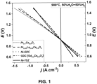
- Spannungs-Stromdichte Diagramm;
- Figur 2:
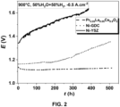
- Spannungs-Zeit-Diagramm;
- Figur 3:
- Aufbau einer SOC.
- In der
Figur 1 wird eine an die Elektroden der hergestellten SOCs angelegte Spannung und die resultierende Stromdichte in Abhängigkeit von der angelegten Spannung gezeigt. - Die hergestellten Einzelzellen wurden in einen keramischen Aufbau für die anschließenden elektrochemischen Messungen eingebaut und mithilfe eines Goldringes wurden die Luft- und Brennstoffelektrode gasdicht getrennt.
- (11) Goldstromsammler wurden für die Kontaktierung der Elektroden benutzt. Nachdem die Zelle installiert wurde, wurde diese auf eine Betriebstemperatur von 900°C unter der Verwendung von Stickstoff auf der Brennstoffelektrodenseite und Luft auf der Luftelektrodenseite aufgeheizt. Nach dem Aufheizen wurden dann die jeweiligen Betriebsbedingungen der CO2, CO- und Wasserdampfelektrolyse angefahren. Die elektrochemischen Messungen wurden mithilfe eines Ivium Vertex Potentiostaten der Firma Ivium Technologies BV, Eindhoven, Niederlande, ausgeführt.
- Es konnte mithilfe von Messungen gezeigt werden, dass die Benutzung des Elektrodenmaterials eine höhere Leistung im Vergleich zu den herkömmlichen Ni-YSZ und Ni-GDC Materialien in der Wasserelektrolyse aufweist. Ein Beispiel für solche Messung wird in der
Figur 1 gezeigt, die Strom Spannungs-Kennlinien zeigt. Aufgetragen ist eine gemessene Spannung E in [V] gegenüber der Stromdichte j in [A/cm2]. Beim Verbrauch von Energie, daher eine negativen Stromdichte in derFigur 1 auf der linken Seite, findet die Elektrolyse von Wasserdampf statt. Bei der Herstellung von elektrischer Energie, daher einer positiven Stromdichte in derFigur 1 auf der rechten Seite, findet der Brennstofzellenbetrieb mit Wasserstoff als Brenngas statt. Es wurden verschiedene Brennstoffelektroden in einem identischen Zelldesign miteinander verglichen, bei denen bei gleichem Aufbau und gleichen Dimensionen Brennstoffelektroden aus Pr0.1Ce0.9O2-δ, Pr0.05La0.05Ce0.9O2-δ, Ni-GDC, GDC sowie Ni-YSZ gebildet worden sind. Der Elektrolyt ist bei allen Zellen aus 8YSZ und die Luftelektrode aus LSCF. Betrieben wurden die Festoxidzellen bei einer Temperatur von 900°C. Als Brennstoff wurde ein Gemisch aus Wasserdampf und Wasserstoff zugeführt. Die größte elektrische Leistung im Elektrolysebetrieb konnte mit der aus Pr0.1Ce0.9O2-δ bestehenden Elektrode erzielt werden. Die zweithöchste mit der Pr0.05La0.05Ce0.9O2-δ Elektrode. Daher wurde bei einer Spannung von 1.5V die höchsten Beträge der Stromdichte j für die Pr0.1Ce0.9O2-δ und Pr0.05La0.05Ce0.9O2-δ Elektroden gemessen. - Es wurde außerdem ein konstanter Strom im Elektrolysebetrieb angelegt und die resultierende Spannung in Abhängigkeit von der Zeit gemessen. Beispiele für Ergebnisse werden in der
Figur 2 gezeigt. In derFigur 2 werden Ergebnisse zu Stabilitätsuntersuchungen bei einer Temperatur von 900°C und einer Stromdicht von - 0.5 A/cm2 gezeigt. Aufgetragen ist die Spannung E in [V] gegen die Zeit in [h]. DieFigur 2 verdeutlicht, dass die Brennstoffzelle mit der aus Pr0.05La0.05Ce0.9O2-δ bestehenden Brennstoffelektrode sich wesentlich langzeitstabiler verhalten hat im Vergleich zu aus Ni-YSZ sowie Ni-GDC bestehenden Brenngaselektroden. - In der
Figur 3 wird ein Beispiel für den Aufbau und den Betrieb einer Brennstoffzelle mit einer Anode 1, einem Elektrolyten 2 und einer Kathode 3 im Schnitt gezeigt. Der Elektrolyt 2 befindet sich zwischen der Anode 1 und der Kathode 3. An die Anode 1 grenzt ein Anodenraum 4. Der Anodenraum 4 weist einen Einlass 5 für ein Brenngas wie zum Beispiel Wasserstoff auf. Es gibt einen Auslass 6 für Anodenraum 4 entstandenen Wasserdampf sowie überschüssigen Wasserstoff. An die Kathode 3 grenzt ein Kathodenraum 7. Der Kathodenraum 7 weist einen Einlass 8 für ein Sauerstoff haltiges Gas auf. Der Kathodenraum 7 weist einen Auslass 9 für überschüssiges Gas auf. Ein elektrischer Leiter 10 kann einen elektrischen Verbraucher 11 mit der Anode 1 und der Kathode 3 verbinden, um den elektrischen Verbraucher 11 mit Strom versorgen zu können, der durch den Betrieb der Brennstoffzelle erzeugt wird. - Der in der
Figur 3 gezeigte Aufbau kann auch als Elektrolyseur dienen, wenn der elektrische Verbraucher 11 gegen eine Gleichstromquelle ausgetauscht wird. Der Elektrode 1 kann dann Wasserdampf als Brennstoff zugeführt werden. Die Elektrode 1 ist dann eine Kathode. Die Elektrode 3 ist folglich dann die Anode. - An der Kathode entsteht während des Betriebs Wasserstoff. An der Anode entsteht während des Betriebs Sauerstoff.
Claims (15)
- Festoxidzelle mit einem Elektrolyten (2), wobei auf gegenüberliegenden Seiten des Elektrolyten (2) gasdurchlässige Elektroden (1, 3) angebracht sind, dadurch gekennzeichnet, dass die Brennstoffelektrode (1) Ce1-xMxO2-δ mit M = Praseodym (Pr) und/oder Lanthan (La) und/oder Samarium (Sm) und/oder Neodym (Nd) umfasst.
- Festoxidzelle nach dem vorhergehenden Anspruch, dadurch gekennzeichnet, dass x = 0 bis 0.3 ist.
- Festoxidzelle nach Anspruch 1, dadurch gekennzeichnet, dass die Brennstoffelektrode (1) Pr0.1Ce0.9O2-δ oder Pr0.3Ce0.7O2-δ oder Pr0.05La0.05Ce0.9O2-δ umfasst.
- Festoxidzelle nach einem der vorhergehenden Ansprüche, dadurch gekennzeichnet, dass in der Brennstoffelektrode Kobalt, Titanium, Platin oder Kupfer oder Nickel infiltriert sind oder die Brennstoffelektrode mit Platin oder Kupfer oder Nickel dotiert ist.
- Festoxidzelle nach einem der vorhergehenden Ansprüche, dadurch gekennzeichnet, dass sich zwischen der Brennstoffelektrode (1) und dem Elektrolyten (2) eine Barriere befindet, wobei die Barriere dotiertes Ceroxid aufweist.
- Festoxidzelle nach dem vorhergehenden Anspruch, dadurch gekennzeichnet, dass die Barriere mit Gadolinium dotiertes Ceroxid (GDC) oder mit Samariumoxid dotiertes Ceroxid (SmDC) aufweist.
- Festoxidzelle nach dem vorhergehenden Anspruch, dadurch gekennzeichnet, dass die Barriere mit 10 Gew.-% bis 20 Gew.-% dotiert ist.
- Festoxidzelle nach einem der vorhergehenden Ansprüche, dadurch gekennzeichnet, dass die Brennstoffelektrode (1) kein Nickel umfasst oder der Anteil an Nickel maximal 10 Gew.-% beträgt.
- Festoxidzelle nach einem der vorhergehenden Ansprüche, dadurch gekennzeichnet, dass der Elektrolyt (2) aus einem gasdichten keramischen Werkstoff besteht, der Sauerstoffionen leiten kann und für Elektronen isolierend wirkt.
- Festoxidzelle nach dem vorhergehenden Anspruch, dadurch gekennzeichnet, dass der Elektrolyt aus Yttrium-stabilisiertem Zirconiumoxid (YSZ) oder aus Strontium und Magnesium dotiertem Lanthangalliumoxid (LSGM) oder aus mit Gadolinium dotiertem Ceroxid (GDC) besteht.
- Festoxidzelle nach einem der vorhergehenden Ansprüche, dadurch gekennzeichnet, dass die für Sauerstoff vorgesehene Elektrode (3) aus einem Perowskit-Verbundwerkstoff besteht.
- Festoxidzelle nach einem der vorhergehenden Ansprüche, dadurch gekennzeichnet, dass die für Sauerstoff vorgesehene Elektrode (3) Lanthan-Strontium-Manganit umfasst und/oder Yttrium-stabilisiertes Zirkoniumoxid umfasst,
oderLanthan-Strontium-Kobaltit und/oder Lanthan-Strontium-Eisenumfasst umfasst oderSamarium-Strontium-Kobaltit umfasst. - Festoxidzelle nach dem vorhergehenden Anspruch, dadurch gekennzeichnet, dass eine Trennschicht aus einer Cerverbindung zwischen dem Elektrolyten (2) und der für Sauerstoff vorgesehene Elektrode (3) vorhanden ist.
- Verfahren für eine Festoxidzelle nach einem der vorhergehenden Ansprüche, dadurch gekennzeichnet, dass die Festoxidzelle bei einer Temperatur betrieben wird, die zwischen 600°C bis 900°C liegt.
- Verfahren nach dem vorhergehenden Anspruch, dadurch gekennzeichnet, dass eine Elektrolyse durchgeführt wird.
Applications Claiming Priority (1)
| Application Number | Priority Date | Filing Date | Title |
|---|---|---|---|
| DE102023207910.0A DE102023207910A1 (de) | 2023-08-17 | 2023-08-17 | Festoxidzelle mit nickelfreier Brennstoffelektrode |
Publications (2)
| Publication Number | Publication Date |
|---|---|
| EP4510248A2 true EP4510248A2 (de) | 2025-02-19 |
| EP4510248A3 EP4510248A3 (de) | 2025-02-26 |
Family
ID=92258921
Family Applications (1)
| Application Number | Title | Priority Date | Filing Date |
|---|---|---|---|
| EP24193003.1A Pending EP4510248A3 (de) | 2023-08-17 | 2024-08-06 | Festoxidzelle mit nickelfreier brennstoffelektrode |
Country Status (2)
| Country | Link |
|---|---|
| EP (1) | EP4510248A3 (de) |
| DE (1) | DE102023207910A1 (de) |
Family Cites Families (7)
| Publication number | Priority date | Publication date | Assignee | Title |
|---|---|---|---|---|
| DE10218074A1 (de) | 2002-04-23 | 2003-11-13 | Fraunhofer Ges Forschung | Hochtemperatur-Festelektrolyt-Brennstoffzelle umfassend einen Verbund aus nanoporösen Dünnschichtelektroden und einem strukturiertem Elektrolyt |
| US7851103B2 (en) * | 2006-10-26 | 2010-12-14 | Toto Ltd. | Solid oxide fuel cell with lanthanum-gallate oxide and having high output performance |
| DE102007015358A1 (de) | 2007-03-30 | 2008-10-02 | Forschungszentrum Jülich GmbH | Schichtsystem für einen Elektrolyten einer Hochtemperatur-Brennstoffzelle sowie Verfahren zur Herstellung desselben |
| JP5796591B2 (ja) | 2013-03-21 | 2015-10-21 | 株式会社豊田中央研究所 | エネルギー変換装置用電極、それを用いたエネルギー変換装置およびエネルギー変換方法 |
| GB2557344B (en) * | 2016-12-08 | 2021-05-19 | Ceres Ip Co Ltd | Anode |
| DE102017009786A1 (de) | 2017-10-20 | 2019-04-25 | Forschungszentrum Jülich GmbH | Brenngaselektrode sowie Verfahren zur Herstellung einer Brenngaselektrode |
| KR20240118893A (ko) * | 2021-12-22 | 2024-08-05 | 유니버시티 오브 매릴랜드, 칼리지 파크 | 다공성 층을 갖는 고체 산화물 세포, 및 그 제조 방법 |
-
2023
- 2023-08-17 DE DE102023207910.0A patent/DE102023207910A1/de active Pending
-
2024
- 2024-08-06 EP EP24193003.1A patent/EP4510248A3/de active Pending
Also Published As
| Publication number | Publication date |
|---|---|
| DE102023207910A1 (de) | 2025-02-20 |
| EP4510248A3 (de) | 2025-02-26 |
Similar Documents
| Publication | Publication Date | Title |
|---|---|---|
| DE60101660T2 (de) | Festoxidbrennstoffzelle | |
| DE60103347T2 (de) | Festoxidbrennstoffzelle mit unterstütztem elektrolytischem Film | |
| DE60120227T2 (de) | Leitfähiges material mit mindestens zwei phasen | |
| DE112016004530T5 (de) | Zusammensetzung für Brennstoffzellenelektrode | |
| DE112012001479T5 (de) | Brennstoffzelle | |
| Zhong et al. | Defect-induced pyrochlore Pr2Zr2O7 cathode rich in oxygen vacancies for direct ammonia solid oxide fuel cells | |
| JP7231431B2 (ja) | 電気化学セル | |
| DE10130783A1 (de) | Brennstoffzelle | |
| DE19782271B4 (de) | Sauerstoffverbundelektroden/Elektrolyt-Struktur und Verfahren zu deren Herstellung | |
| Li et al. | Enhanced performance of solid oxide fuel cells using highly conductive Ca2+ and F− co-doped Gd0. 2Ce0. 8O1. 9 buffer layer | |
| Jo et al. | Enhancement of electrochemical performance and thermal compatibility of GdBaCo2/3Fe2/3Cu2/3O5+ δ cathode on Ce1. 9Gd0. 1O1. 95 electrolyte for IT-SOFCs | |
| DE69505784T2 (de) | Fester Elektrolyt für eine Brennstoffzelle und sein Herstellungsverfahren | |
| DE102013007637B4 (de) | Kathoden-Elektrolyt-Anodeneinheit von Hochtemperatur-Brennstoffzellen | |
| EP1497884A2 (de) | Hochtemperatur-festelektrolyt- brennstoffzelle umfassend einen verbund aus nanoporösen dünnschichtelektroden und einem strukturiertem elektrolyt | |
| Ishihara et al. | Novel fast oxide ion conductor and application for the electrolyte of solid oxide fuel cell | |
| DE112023000760T5 (de) | Elektrochemische zelle | |
| DE112021007166T5 (de) | Brennstoffelektrode und elektrochemische zelle | |
| Wei et al. | Anodic polarization induced performance loss in GdBaCo2O5+ δ oxygen electrode under solid oxide electrolysis cell conditions | |
| WO2021085426A1 (ja) | 一酸化炭素製造装置 | |
| EP4510248A2 (de) | Festoxidzelle mit nickelfreier brennstoffelektrode | |
| US12392045B2 (en) | Electrode material, method for the production thereof, and use of same | |
| EP2837053B1 (de) | Schwefeltolerantes hochtemperatur-brennstoffzellensystem mit internem wassergas-shift-katalysator | |
| US7758992B2 (en) | Copper-substituted perovskite compositions for solid oxide fuel cell cathodes and oxygen reduction electrodes in other electrochemical devices | |
| EP4673587A1 (de) | Festoxidelektrolysezelle mit kathode und verfahren | |
| DE10209791C1 (de) | Anodenmaterial für Hochtemperatur-Brennstoffzellen |
Legal Events
| Date | Code | Title | Description |
|---|---|---|---|
| PUAI | Public reference made under article 153(3) epc to a published international application that has entered the european phase |
Free format text: ORIGINAL CODE: 0009012 |
|
| STAA | Information on the status of an ep patent application or granted ep patent |
Free format text: STATUS: THE APPLICATION HAS BEEN PUBLISHED |
|
| PUAL | Search report despatched |
Free format text: ORIGINAL CODE: 0009013 |
|
| AK | Designated contracting states |
Kind code of ref document: A2 Designated state(s): AL AT BE BG CH CY CZ DE DK EE ES FI FR GB GR HR HU IE IS IT LI LT LU LV MC ME MK MT NL NO PL PT RO RS SE SI SK SM TR |
|
| AK | Designated contracting states |
Kind code of ref document: A3 Designated state(s): AL AT BE BG CH CY CZ DE DK EE ES FI FR GB GR HR HU IE IS IT LI LT LU LV MC ME MK MT NL NO PL PT RO RS SE SI SK SM TR |
|
| RIC1 | Information provided on ipc code assigned before grant |
Ipc: H01M 8/12 20160101ALN20250123BHEP Ipc: H01M 4/90 20060101AFI20250123BHEP |
|
| STAA | Information on the status of an ep patent application or granted ep patent |
Free format text: STATUS: REQUEST FOR EXAMINATION WAS MADE |
|
| 17P | Request for examination filed |
Effective date: 20250806 |