EP4510248A2 - Cellule à oxyde solide avec électrode de combustible sans nickel - Google Patents
Cellule à oxyde solide avec électrode de combustible sans nickel Download PDFInfo
- Publication number
- EP4510248A2 EP4510248A2 EP24193003.1A EP24193003A EP4510248A2 EP 4510248 A2 EP4510248 A2 EP 4510248A2 EP 24193003 A EP24193003 A EP 24193003A EP 4510248 A2 EP4510248 A2 EP 4510248A2
- Authority
- EP
- European Patent Office
- Prior art keywords
- solid oxide
- electrode
- cell according
- oxide cell
- electrolyte
- Prior art date
- Legal status (The legal status is an assumption and is not a legal conclusion. Google has not performed a legal analysis and makes no representation as to the accuracy of the status listed.)
- Pending
Links
Images

Classifications
-
- H—ELECTRICITY
- H01—ELECTRIC ELEMENTS
- H01M—PROCESSES OR MEANS, e.g. BATTERIES, FOR THE DIRECT CONVERSION OF CHEMICAL ENERGY INTO ELECTRICAL ENERGY
- H01M4/00—Electrodes
- H01M4/86—Inert electrodes with catalytic activity, e.g. for fuel cells
- H01M4/90—Selection of catalytic material
- H01M4/9016—Oxides, hydroxides or oxygenated metallic salts
- H01M4/9025—Oxides specially used in fuel cell operating at high temperature, e.g. SOFC
-
- H—ELECTRICITY
- H01—ELECTRIC ELEMENTS
- H01M—PROCESSES OR MEANS, e.g. BATTERIES, FOR THE DIRECT CONVERSION OF CHEMICAL ENERGY INTO ELECTRICAL ENERGY
- H01M4/00—Electrodes
- H01M4/86—Inert electrodes with catalytic activity, e.g. for fuel cells
- H01M4/90—Selection of catalytic material
- H01M4/9041—Metals or alloys
- H01M4/905—Metals or alloys specially used in fuel cell operating at high temperature, e.g. SOFC
- H01M4/9066—Metals or alloys specially used in fuel cell operating at high temperature, e.g. SOFC of metal-ceramic composites or mixtures, e.g. cermets
-
- H—ELECTRICITY
- H01—ELECTRIC ELEMENTS
- H01M—PROCESSES OR MEANS, e.g. BATTERIES, FOR THE DIRECT CONVERSION OF CHEMICAL ENERGY INTO ELECTRICAL ENERGY
- H01M8/00—Fuel cells; Manufacture thereof
- H01M8/10—Fuel cells with solid electrolytes
- H01M8/12—Fuel cells with solid electrolytes operating at high temperature, e.g. with stabilised ZrO2 electrolyte
- H01M2008/1293—Fuel cells with solid oxide electrolytes
-
- Y—GENERAL TAGGING OF NEW TECHNOLOGICAL DEVELOPMENTS; GENERAL TAGGING OF CROSS-SECTIONAL TECHNOLOGIES SPANNING OVER SEVERAL SECTIONS OF THE IPC; TECHNICAL SUBJECTS COVERED BY FORMER USPC CROSS-REFERENCE ART COLLECTIONS [XRACs] AND DIGESTS
- Y02—TECHNOLOGIES OR APPLICATIONS FOR MITIGATION OR ADAPTATION AGAINST CLIMATE CHANGE
- Y02E—REDUCTION OF GREENHOUSE GAS [GHG] EMISSIONS, RELATED TO ENERGY GENERATION, TRANSMISSION OR DISTRIBUTION
- Y02E60/00—Enabling technologies; Technologies with a potential or indirect contribution to GHG emissions mitigation
- Y02E60/30—Hydrogen technology
- Y02E60/50—Fuel cells
Definitions
- the invention relates to a solid oxide cell (SOC), which includes solid oxide fuel cells (SOFCs), solid oxide electrolysis cells (SOECs) and reversible solid oxide cells (RSOCs).
- SOCs are electrochemical devices that can function as energy storage or energy conversion devices.
- the invention also relates to a method for operating the solid oxide cell.
- a typical SOC consists of a gas-tight electrolyte surrounded by two porous electrodes, namely the fuel electrode and the air/oxygen electrode.
- electrolysis mode H 2 O, CO 2 or a gas mixture of both can be converted into H 2 , CO or synthesis gas.
- Electrical energy can therefore be converted into chemical energy.
- SOFC mode the stored chemical energy can be converted back into electrical energy.
- gases such as H 2 , H 2 O, CO, CO 2 , hydrocarbon-based gases, etc. can be used in both electrolysis and fuel cell operation.
- the object of the present invention is to further develop a SOC.
- a long service life of the fuel electrodes in SOEC and SOFC systems is to be achieved.
- a method for production comprises the features of the independent claim.
- the dependent claims relate to advantageous embodiments.
- a solid oxide cell has an electrolyte, with gas-permeable electrical conductors as anode and cathode on opposite sides of the electrolyte.
- the cathode and/or anode can be attached directly or indirectly to the electrolyte.
- the anode and cathode can also advantageously be ionic conductors.
- the anode is the electrode that absorbs electrons during operation, i.e. an oxidation reaction of gas components takes place at this electrode.
- the anode is the electrode that is intended and suitable for supplying fuel during fuel cell operation.
- hydrogen can be supplied to the anode during fuel cell operation.
- Hydrogen molecules are oxidized and then give up their electrons to the anode.
- the anode is therefore also called the fuel electrode.
- An oxygen-containing gas such as air or pure oxygen can be supplied to the cathode during fuel cell operation.
- a reduction reaction of oxygen takes place at the cathode, i.e. the oxygen molecules absorb electrons from the cathode.
- the cathode is the fuel electrode.
- water vapor can be fed to the cathode in order to generate hydrogen.
- the fuel electrode can consist of just one layer.
- the other electrode can also consist of just one layer, i.e. just one material.
- the fuel electrode and/or the other electrode can also comprise more than one layer. Layers of an electrode can consist of different materials.
- the fuel electrode and/or the other electrode can each comprise a layer that conducts electricity and is catalytically active. An electrochemical reaction takes place in the catalytically active layer. For example, water vapor is converted into hydrogen by absorbing electrons.
- the electrode can comprise a porous layer that is advantageously not catalytically active.
- the catalytically active layer can advantageously be located between the electrolyte layer and the non-catalytically active layer of the electrode. In this way, the use of materials and mass transport can be optimized.
- An electrode can comprise a current collector layer.
- the current collector layer can be a third layer of an electrode.
- the current collector layer can be located on the outside of the electrode, i.e. as far away as possible from the electrolyte layer.
- the current collector layer can consist of gold, platinum or nickel, for example.
- Electrodes can be not only electrically conductive, but preferably also ionically conductive.
- the material of an electrode that is both electrically and ionically conductive is also called MIEC.
- the material can be a cermet, for example.
- the material can, for example, comprise two phases, namely an electrically conductive phase and an ionically conductive phase.
- the material can, for example, be a (mixed) conductive oxide.
- ⁇ represents an oxygen deficit in the material. So there can be a lack of oxygen in the crystal structure. This means that the material does not contain the maximum number of oxygen atoms normally provided for in the chemical formula. This can be beneficial in, for example, solid oxide fuel cells (SOFCs), as the oxygen can easily move through the material in the event of an oxygen deficit to maintain the electrochemistry in the fuel cell.
- SOFCs solid oxide fuel cells
- high stability can be achieved.
- the long-term stability for use as a fuel electrode for SOFC, RSOC and SOEC systems can thus be significantly improved compared to conventional systems.
- the fuel electrode or at least one layer of the fuel electrode particularly preferably consists of Pr 0.1 Ce 0.9 O 2- ⁇ , Pr 0.3 Ce 0.7 O 2- ⁇ or Pr 0.05 La 0.05 Ce 0.9 O 2- ⁇ , in order to obtain a long-term stable, high-performance solid oxide cell.
- cobalt, titanium, platinum, copper and/or nickel are infiltrated into the fuel electrode. It is possible that the fuel electrode is doped with cobalt, titanium, platinum, copper and/or nickel.
- the proportion of cobalt, titanium, platinum, copper and/or nickel in the fuel electrode can be more than 1 wt.% or more than 2 wt.% and/or less than 5 wt.% or less than 10 wt.%. From 1 wt.% or more than 2 wt.%, significant technical advantages result. From 5 wt.% or 10 wt.%, no significant technical advantages are achieved through the increased use of material. In particular, the proportion of nickel can therefore be low compared to the nickel content of conventional nickel-containing fuel electrodes. In this way, the electrochemical properties of a fuel electrode can be further improved without affecting long-term stability.
- a fuel electrode or a layer of a fuel electrode can be made from Ce 1-x Gd x O 2- ⁇ .
- the fuel electrode made from Ce 1-x Gd x O 2- ⁇ is then doped or infiltrated with nickel.
- the proportion of nickel must then be less than 5% by weight.
- a barrier can be located between the fuel electrode and the electrolyte to improve properties of the solid oxide cell.
- the barrier can, for example, comprise or consist of doped cerium oxide.
- the barrier can comprise or consist of gadolinium-doped cerium oxide (GDC) or samarium oxide-doped cerium oxide (SmDC).
- GDC gadolinium-doped cerium oxide
- SmDC samarium oxide-doped cerium oxide
- the barrier is basically a layer located between two other layers.
- the doping can be at least 10 wt.% and/or up to 20 wt.%.
- the electrolyte can consist of a gas-tight, ceramic material that can conduct oxygen ions at least at sufficiently high temperatures, such as 600°C and above, and has an insulating effect on electrons.
- the electrolyte may consist of or comprise yttrium-stabilized zirconia (YSZ), strontium and magnesium doped lanthanum gallium oxide (LSGM), or gadolinium doped ceria (GDC).
- YSZ yttrium-stabilized zirconia
- LSGM strontium and magnesium doped lanthanum gallium oxide
- GDC gadolinium doped ceria
- the other electrode or at least a layer of the other electrode may consist of a perovskite composite material.
- the other electrode may consist of lanthanum strontium manganite, ((La,Sr)MnO 3 or LSM)) or comprise LSM.
- the other electrode may consist of lanthanum strontium cobaltite, ((La,Sr)CoO 3 or LSC) or comprise LSC.
- the other electrode may consist of lanthanum strontium iron, ((La,Sr)FeO 3 or LSF) or comprise LSF.
- the other electrode may consist of samarium strontium cobaltite ((Sm,Sr)CoO 3 or SSC) or comprise SSC.
- other electrode is meant the electrode which is in the Oxygen is supplied during fuel cell operation or from which oxygen escapes during electrolysis operation.
- the separating layer may, for example, be a cerium compound between the electrolyte and the fuel electrode.
- Ce 1-x M x O 2- ⁇ can conduct electronically and ionically under oxidizing and reducing conditions.
- a gas-permeable layer formed from Ce 1-x M x O 2- ⁇ with M praseodymium (Pr) and/or lanthanum (La) and/or samarium (Sm) and/or neodymium (Nd) can therefore be adjacent to a layer of YZS, LSGM or GDC in order to obtain a long-term stable solid oxide cell.
- Pr praseodymium
- La lanthanum
- Sm samarium
- Nd neodymium
- the fuel electrode is suitable for various gas compositions, such as H 2 /H 2 O or CO/CO 2 mixtures.
- the solid oxide cell is usually operated in the temperature range of 600°C to 1000°C or 650°C to 900°C.
- the solid oxide cell can be plate-shaped.
- the anode, electrolyte and cathode can then be shaped like flat plates.
- An anode chamber can adjoin the anode, which can be separated from a cathode chamber adjoining the cathode.
- the anode chamber can have an inlet and an outlet for gas.
- the cathode chamber can have an inlet and an outlet for gas.
- a fuel gas such as hydrogen can be introduced into the anode chamber.
- the fuel gas can be passed through the anode chamber along the anode.
- an oxygen-containing gas such as air or oxygen can be introduced into the cathode chamber.
- air or oxygen can then be passed through the cathode chamber along the cathode.
- a plate-shaped interconnector can be used to electrically connect two plate-shaped solid oxide cells.
- An interconnector is an electrically conductive connecting part that can be made of metal.
- the solid oxide cell can be tubular.
- one electrode can be a tube.
- the outside of this electrode can be coated with the electrolyte.
- the outside of the electrolyte can be coated with the other, then external electrode.
- An electrically conductive interconnector can be connected to the tubular, internal electrode and led through the coatings to the outside. The interconnector is then electrically separated from the other, external electrode and therefore does not touch the external electrode.
- the fuel electrode can be produced by sintering in a high-temperature furnace.
- the electrode material can first be produced in powder form from its individual components, for example using the citrate-nitrate process described below.
- the electrode material can then be calcined.
- An electrode paste can be produced from the electrode powder using organic solvents and binders, which can be used in a screen printing process, for example.
- the electrode paste can either be applied directly to the solid oxide electrolyte or, for example, to an additional barrier layer, which can consist of GDC, for example.
- the fuel electrode is sintered at high temperatures (e.g. 1400°C or 1450°C for 4 hours) in a high-temperature furnace. Lower sintering temperatures can sometimes lead to poorer performance and/or delamination of the fuel electrode.
- variable air electrode material or cathode material e.g. Pt, LSCF or LSCF-GDC
- An additional barrier layer e.g. made of GDC, can be provided between the other electrode produced in this way (air electrode) and the solid oxide electrolyte.
- a current collecting layer made of e.g. gold can be applied to the fuel electrode. It can then also be sintered.
- the SOCs produced in this way can be used in larger SOC systems (stacks).
- a stack consists of many units of SOCs that are connected to one another by interconnectors.
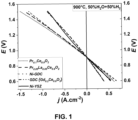
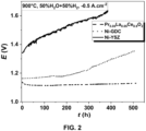
- Example 1 Pr 0.05 La 0.05 Ce 0.9 O 2- ⁇ fuel electrode with GDC barrier layer
- the corresponding precursors were pre-dissolved in deionized water and then citric acid was added and dissolved with stirring at room temperature.
- the molar ratio of total metal ions to citric acid was 1:1:1. While heating this mixture on a hot plate at 80°C, the excess water and nitrate gases were removed, forming a viscous gel that later turned into a light brown foam. Upon further heating to 150°C, the foam self-ignited due to the citric acid, leaving a powder. The powder was then calcined at 600°C for 3 hours to obtain a pure phase.
- PrLaCeOz-s electrode material with a thickness of approx. 10 to 15 ⁇ m was applied.
- the fuel electrode and the GDC barrier layer were co-sintered at 1400°C for 4 hours in air.
- a thin GDC barrier layer with a thickness of approximately 4 - 5 ⁇ m was applied to the other side of the electrolyte using a screen printing process and sintered at the same time at 1400°C.
- the LSCF air electrode layer with a thickness of about 40 ⁇ m was applied to the GDC barrier layer and sintered at 1080 °C for 3 h under air atmosphere.
- the active area of the individual cells was 0.785 cm 2 .
- a solid oxide cell with a Pr 0.05 La 0.05 Ce 0.9 O 2- ⁇ fuel electrode and a GDC barrier layer was fabricated.
- Solid oxide cells with other compositions were prepared and investigated in essentially the same way.
- the manufactured individual cells were installed in a ceramic structure for the subsequent electrochemical measurements and the air and fuel electrodes were separated gas-tight using a gold ring.
- Gold current collectors were used to contact the electrodes. After the cell was installed, it was heated to an operating temperature of 900°C using nitrogen on the fuel electrode side and air on the air electrode side. After heating, the respective operating conditions of CO 2 , CO and water vapor electrolysis were then started. The electrochemical measurements were carried out using an Ivium Vertex potentiostat from Ivium Technologies BV, Eindhoven, the Netherlands.
- an electrolyte 2 and a cathode 3 is shown in section.
- the electrolyte 2 is located between the anode 1 and the cathode 3.
- An anode chamber 4 is adjacent to the anode 1.
- the anode chamber 4 has an inlet 5 for a fuel gas such as hydrogen.
- a cathode chamber 7 is adjacent to the cathode 3.
- the cathode chamber 7 has an inlet 8 for an oxygen-containing gas.
- the cathode chamber 7 has an outlet 9 for excess gas.
- An electrical conductor 10 can connect an electrical consumer 11 to the anode 1 and the cathode 3 in order to supply the electrical To supply consumer 11 with electricity generated by the operation of the fuel cell.
- the one in the Figure 3 The structure shown can also serve as an electrolyzer if the electrical consumer 11 is replaced by a direct current source. Water vapor can then be supplied to the electrode 1 as fuel. The electrode 1 is then a cathode. The electrode 3 is therefore then the anode.
- Hydrogen is produced at the cathode during operation.
- Oxygen is produced at the anode during operation.
Landscapes
- Chemical & Material Sciences (AREA)
- Engineering & Computer Science (AREA)
- Materials Engineering (AREA)
- Chemical Kinetics & Catalysis (AREA)
- Electrochemistry (AREA)
- General Chemical & Material Sciences (AREA)
- Ceramic Engineering (AREA)
- Composite Materials (AREA)
- Inert Electrodes (AREA)
- Fuel Cell (AREA)
Applications Claiming Priority (1)
| Application Number | Priority Date | Filing Date | Title |
|---|---|---|---|
| DE102023207910.0A DE102023207910A1 (de) | 2023-08-17 | 2023-08-17 | Festoxidzelle mit nickelfreier Brennstoffelektrode |
Publications (2)
| Publication Number | Publication Date |
|---|---|
| EP4510248A2 true EP4510248A2 (fr) | 2025-02-19 |
| EP4510248A3 EP4510248A3 (fr) | 2025-02-26 |
Family
ID=92258921
Family Applications (1)
| Application Number | Title | Priority Date | Filing Date |
|---|---|---|---|
| EP24193003.1A Pending EP4510248A3 (fr) | 2023-08-17 | 2024-08-06 | Cellule à oxyde solide avec électrode de combustible sans nickel |
Country Status (2)
| Country | Link |
|---|---|
| EP (1) | EP4510248A3 (fr) |
| DE (1) | DE102023207910A1 (fr) |
Family Cites Families (7)
| Publication number | Priority date | Publication date | Assignee | Title |
|---|---|---|---|---|
| DE10218074A1 (de) | 2002-04-23 | 2003-11-13 | Fraunhofer Ges Forschung | Hochtemperatur-Festelektrolyt-Brennstoffzelle umfassend einen Verbund aus nanoporösen Dünnschichtelektroden und einem strukturiertem Elektrolyt |
| US7851103B2 (en) * | 2006-10-26 | 2010-12-14 | Toto Ltd. | Solid oxide fuel cell with lanthanum-gallate oxide and having high output performance |
| DE102007015358A1 (de) | 2007-03-30 | 2008-10-02 | Forschungszentrum Jülich GmbH | Schichtsystem für einen Elektrolyten einer Hochtemperatur-Brennstoffzelle sowie Verfahren zur Herstellung desselben |
| JP5796591B2 (ja) | 2013-03-21 | 2015-10-21 | 株式会社豊田中央研究所 | エネルギー変換装置用電極、それを用いたエネルギー変換装置およびエネルギー変換方法 |
| GB2557344B (en) * | 2016-12-08 | 2021-05-19 | Ceres Ip Co Ltd | Anode |
| DE102017009786A1 (de) | 2017-10-20 | 2019-04-25 | Forschungszentrum Jülich GmbH | Brenngaselektrode sowie Verfahren zur Herstellung einer Brenngaselektrode |
| KR20240118893A (ko) * | 2021-12-22 | 2024-08-05 | 유니버시티 오브 매릴랜드, 칼리지 파크 | 다공성 층을 갖는 고체 산화물 세포, 및 그 제조 방법 |
-
2023
- 2023-08-17 DE DE102023207910.0A patent/DE102023207910A1/de active Pending
-
2024
- 2024-08-06 EP EP24193003.1A patent/EP4510248A3/fr active Pending
Also Published As
| Publication number | Publication date |
|---|---|
| DE102023207910A1 (de) | 2025-02-20 |
| EP4510248A3 (fr) | 2025-02-26 |
Similar Documents
| Publication | Publication Date | Title |
|---|---|---|
| DE60101660T2 (de) | Festoxidbrennstoffzelle | |
| DE60103347T2 (de) | Festoxidbrennstoffzelle mit unterstütztem elektrolytischem Film | |
| DE60120227T2 (de) | Leitfähiges material mit mindestens zwei phasen | |
| DE112016004530T5 (de) | Zusammensetzung für Brennstoffzellenelektrode | |
| DE112012001479T5 (de) | Brennstoffzelle | |
| Zhong et al. | Defect-induced pyrochlore Pr2Zr2O7 cathode rich in oxygen vacancies for direct ammonia solid oxide fuel cells | |
| JP7231431B2 (ja) | 電気化学セル | |
| DE10130783A1 (de) | Brennstoffzelle | |
| DE19782271B4 (de) | Sauerstoffverbundelektroden/Elektrolyt-Struktur und Verfahren zu deren Herstellung | |
| Li et al. | Enhanced performance of solid oxide fuel cells using highly conductive Ca2+ and F− co-doped Gd0. 2Ce0. 8O1. 9 buffer layer | |
| Jo et al. | Enhancement of electrochemical performance and thermal compatibility of GdBaCo2/3Fe2/3Cu2/3O5+ δ cathode on Ce1. 9Gd0. 1O1. 95 electrolyte for IT-SOFCs | |
| DE69505784T2 (de) | Fester Elektrolyt für eine Brennstoffzelle und sein Herstellungsverfahren | |
| DE102013007637B4 (de) | Kathoden-Elektrolyt-Anodeneinheit von Hochtemperatur-Brennstoffzellen | |
| EP1497884A2 (fr) | Pile a combustible a electrolyte solide a haute temperature, comprenant un composite constitue d'electrodes en couche mince nanoporeuses et d'un electrolyte structure | |
| Ishihara et al. | Novel fast oxide ion conductor and application for the electrolyte of solid oxide fuel cell | |
| DE112023000760T5 (de) | Elektrochemische zelle | |
| DE112021007166T5 (de) | Brennstoffelektrode und elektrochemische zelle | |
| Wei et al. | Anodic polarization induced performance loss in GdBaCo2O5+ δ oxygen electrode under solid oxide electrolysis cell conditions | |
| WO2021085426A1 (fr) | Appareil de production de monoxyde de carbone | |
| EP4510248A2 (fr) | Cellule à oxyde solide avec électrode de combustible sans nickel | |
| US12392045B2 (en) | Electrode material, method for the production thereof, and use of same | |
| EP2837053B1 (fr) | Système de piles à combustible à haute température étant interte au soufre comprenant un catalyseur water gas shift | |
| US7758992B2 (en) | Copper-substituted perovskite compositions for solid oxide fuel cell cathodes and oxygen reduction electrodes in other electrochemical devices | |
| EP4673587A1 (fr) | Cellule d'électrolyse à oxyde solide avec cathode et procédé | |
| DE10209791C1 (de) | Anodenmaterial für Hochtemperatur-Brennstoffzellen |
Legal Events
| Date | Code | Title | Description |
|---|---|---|---|
| PUAI | Public reference made under article 153(3) epc to a published international application that has entered the european phase |
Free format text: ORIGINAL CODE: 0009012 |
|
| STAA | Information on the status of an ep patent application or granted ep patent |
Free format text: STATUS: THE APPLICATION HAS BEEN PUBLISHED |
|
| PUAL | Search report despatched |
Free format text: ORIGINAL CODE: 0009013 |
|
| AK | Designated contracting states |
Kind code of ref document: A2 Designated state(s): AL AT BE BG CH CY CZ DE DK EE ES FI FR GB GR HR HU IE IS IT LI LT LU LV MC ME MK MT NL NO PL PT RO RS SE SI SK SM TR |
|
| AK | Designated contracting states |
Kind code of ref document: A3 Designated state(s): AL AT BE BG CH CY CZ DE DK EE ES FI FR GB GR HR HU IE IS IT LI LT LU LV MC ME MK MT NL NO PL PT RO RS SE SI SK SM TR |
|
| RIC1 | Information provided on ipc code assigned before grant |
Ipc: H01M 8/12 20160101ALN20250123BHEP Ipc: H01M 4/90 20060101AFI20250123BHEP |
|
| STAA | Information on the status of an ep patent application or granted ep patent |
Free format text: STATUS: REQUEST FOR EXAMINATION WAS MADE |
|
| 17P | Request for examination filed |
Effective date: 20250806 |