EP4512453A2 - Verbesserte katheter sowie vorrichtungen und systeme mit solchen kathetern - Google Patents
Verbesserte katheter sowie vorrichtungen und systeme mit solchen kathetern Download PDFInfo
- Publication number
- EP4512453A2 EP4512453A2 EP25151200.0A EP25151200A EP4512453A2 EP 4512453 A2 EP4512453 A2 EP 4512453A2 EP 25151200 A EP25151200 A EP 25151200A EP 4512453 A2 EP4512453 A2 EP 4512453A2
- Authority
- EP
- European Patent Office
- Prior art keywords
- catheter
- pressure
- clot
- distal
- jacket
- Prior art date
- Legal status (The legal status is an assumption and is not a legal conclusion. Google has not performed a legal analysis and makes no representation as to the accuracy of the status listed.)
- Pending
Links
Images









Classifications
-
- A—HUMAN NECESSITIES
- A61—MEDICAL OR VETERINARY SCIENCE; HYGIENE
- A61B—DIAGNOSIS; SURGERY; IDENTIFICATION
- A61B17/00—Surgical instruments, devices or methods
- A61B17/22—Implements for squeezing-off ulcers or the like on inner organs of the body; Implements for scraping-out cavities of body organs, e.g. bones; for invasive removal or destruction of calculus using mechanical vibrations; for removing obstructions in blood vessels, not otherwise provided for
-
- A—HUMAN NECESSITIES
- A61—MEDICAL OR VETERINARY SCIENCE; HYGIENE
- A61L—METHODS OR APPARATUS FOR STERILISING MATERIALS OR OBJECTS IN GENERAL; DISINFECTION, STERILISATION OR DEODORISATION OF AIR; CHEMICAL ASPECTS OF BANDAGES, DRESSINGS, ABSORBENT PADS OR SURGICAL ARTICLES; MATERIALS FOR BANDAGES, DRESSINGS, ABSORBENT PADS OR SURGICAL ARTICLES
- A61L29/00—Materials for catheters, medical tubing, cannulae, or endoscopes or for coating catheters
- A61L29/04—Macromolecular materials
- A61L29/06—Macromolecular materials obtained otherwise than by reactions only involving carbon-to-carbon unsaturated bonds
-
- A—HUMAN NECESSITIES
- A61—MEDICAL OR VETERINARY SCIENCE; HYGIENE
- A61M—DEVICES FOR INTRODUCING MEDIA INTO, OR ONTO, THE BODY; DEVICES FOR TRANSDUCING BODY MEDIA OR FOR TAKING MEDIA FROM THE BODY; DEVICES FOR PRODUCING OR ENDING SLEEP OR STUPOR
- A61M1/00—Suction or pumping devices for medical purposes; Devices for carrying-off, for treatment of, or for carrying-over, body-liquids; Drainage systems
- A61M1/71—Suction drainage systems
- A61M1/74—Suction control
-
- A—HUMAN NECESSITIES
- A61—MEDICAL OR VETERINARY SCIENCE; HYGIENE
- A61M—DEVICES FOR INTRODUCING MEDIA INTO, OR ONTO, THE BODY; DEVICES FOR TRANSDUCING BODY MEDIA OR FOR TAKING MEDIA FROM THE BODY; DEVICES FOR PRODUCING OR ENDING SLEEP OR STUPOR
- A61M1/00—Suction or pumping devices for medical purposes; Devices for carrying-off, for treatment of, or for carrying-over, body-liquids; Drainage systems
- A61M1/71—Suction drainage systems
- A61M1/74—Suction control
- A61M1/75—Intermittent or pulsating suction
-
- A—HUMAN NECESSITIES
- A61—MEDICAL OR VETERINARY SCIENCE; HYGIENE
- A61M—DEVICES FOR INTRODUCING MEDIA INTO, OR ONTO, THE BODY; DEVICES FOR TRANSDUCING BODY MEDIA OR FOR TAKING MEDIA FROM THE BODY; DEVICES FOR PRODUCING OR ENDING SLEEP OR STUPOR
- A61M1/00—Suction or pumping devices for medical purposes; Devices for carrying-off, for treatment of, or for carrying-over, body-liquids; Drainage systems
- A61M1/84—Drainage tubes; Aspiration tips
-
- A—HUMAN NECESSITIES
- A61—MEDICAL OR VETERINARY SCIENCE; HYGIENE
- A61M—DEVICES FOR INTRODUCING MEDIA INTO, OR ONTO, THE BODY; DEVICES FOR TRANSDUCING BODY MEDIA OR FOR TAKING MEDIA FROM THE BODY; DEVICES FOR PRODUCING OR ENDING SLEEP OR STUPOR
- A61M25/00—Catheters; Hollow probes
- A61M25/0009—Making of catheters or other medical or surgical tubes
- A61M25/0012—Making of catheters or other medical or surgical tubes with embedded structures, e.g. coils, braids, meshes, strands or radiopaque coils
-
- A—HUMAN NECESSITIES
- A61—MEDICAL OR VETERINARY SCIENCE; HYGIENE
- A61M—DEVICES FOR INTRODUCING MEDIA INTO, OR ONTO, THE BODY; DEVICES FOR TRANSDUCING BODY MEDIA OR FOR TAKING MEDIA FROM THE BODY; DEVICES FOR PRODUCING OR ENDING SLEEP OR STUPOR
- A61M25/00—Catheters; Hollow probes
- A61M25/0043—Catheters; Hollow probes characterised by structural features
- A61M25/0045—Catheters; Hollow probes characterised by structural features multi-layered, e.g. coated
-
- A—HUMAN NECESSITIES
- A61—MEDICAL OR VETERINARY SCIENCE; HYGIENE
- A61M—DEVICES FOR INTRODUCING MEDIA INTO, OR ONTO, THE BODY; DEVICES FOR TRANSDUCING BODY MEDIA OR FOR TAKING MEDIA FROM THE BODY; DEVICES FOR PRODUCING OR ENDING SLEEP OR STUPOR
- A61M25/00—Catheters; Hollow probes
- A61M25/0043—Catheters; Hollow probes characterised by structural features
- A61M25/005—Catheters; Hollow probes characterised by structural features with embedded materials for reinforcement, e.g. wires, coils, braids
-
- A—HUMAN NECESSITIES
- A61—MEDICAL OR VETERINARY SCIENCE; HYGIENE
- A61M—DEVICES FOR INTRODUCING MEDIA INTO, OR ONTO, THE BODY; DEVICES FOR TRANSDUCING BODY MEDIA OR FOR TAKING MEDIA FROM THE BODY; DEVICES FOR PRODUCING OR ENDING SLEEP OR STUPOR
- A61M25/00—Catheters; Hollow probes
- A61M25/0043—Catheters; Hollow probes characterised by structural features
- A61M25/0054—Catheters; Hollow probes characterised by structural features with regions for increasing flexibility
-
- A—HUMAN NECESSITIES
- A61—MEDICAL OR VETERINARY SCIENCE; HYGIENE
- A61M—DEVICES FOR INTRODUCING MEDIA INTO, OR ONTO, THE BODY; DEVICES FOR TRANSDUCING BODY MEDIA OR FOR TAKING MEDIA FROM THE BODY; DEVICES FOR PRODUCING OR ENDING SLEEP OR STUPOR
- A61M25/00—Catheters; Hollow probes
- A61M25/01—Introducing, guiding, advancing, emplacing or holding catheters
- A61M25/0105—Steering means as part of the catheter or advancing means; Markers for positioning
- A61M25/0108—Steering means as part of the catheter or advancing means; Markers for positioning using radio-opaque or ultrasound markers
-
- A—HUMAN NECESSITIES
- A61—MEDICAL OR VETERINARY SCIENCE; HYGIENE
- A61B—DIAGNOSIS; SURGERY; IDENTIFICATION
- A61B17/00—Surgical instruments, devices or methods
- A61B17/22—Implements for squeezing-off ulcers or the like on inner organs of the body; Implements for scraping-out cavities of body organs, e.g. bones; for invasive removal or destruction of calculus using mechanical vibrations; for removing obstructions in blood vessels, not otherwise provided for
- A61B2017/22051—Implements for squeezing-off ulcers or the like on inner organs of the body; Implements for scraping-out cavities of body organs, e.g. bones; for invasive removal or destruction of calculus using mechanical vibrations; for removing obstructions in blood vessels, not otherwise provided for with an inflatable part, e.g. balloon, for positioning, blocking, or immobilisation
- A61B2017/22065—Functions of balloons
- A61B2017/22067—Blocking; Occlusion
-
- A—HUMAN NECESSITIES
- A61—MEDICAL OR VETERINARY SCIENCE; HYGIENE
- A61B—DIAGNOSIS; SURGERY; IDENTIFICATION
- A61B17/00—Surgical instruments, devices or methods
- A61B17/22—Implements for squeezing-off ulcers or the like on inner organs of the body; Implements for scraping-out cavities of body organs, e.g. bones; for invasive removal or destruction of calculus using mechanical vibrations; for removing obstructions in blood vessels, not otherwise provided for
- A61B2017/22079—Implements for squeezing-off ulcers or the like on inner organs of the body; Implements for scraping-out cavities of body organs, e.g. bones; for invasive removal or destruction of calculus using mechanical vibrations; for removing obstructions in blood vessels, not otherwise provided for with suction of debris
Definitions
- the jacket is formed in at least some regions by positioning a membrane over a helical structure, applying heat so that the membrane reflows such that it forms around the helical structure, winding a tensioned cinch wire around the outside of the membrane such that it forces membrane material into grooves between each loop of the helical structure, heat setting the membrane to fix the corrugations in place, and unwinding the tensioned cinch wire leaving the corrugations behind.
- the method comprises providing the helical support within a polymer jacket which is bonded to a liner to form a base assembly, placing an outer liner which will not bond to the polymer jacket over the jacketed coil, winding the cinch wire in a helix onto the outside of the outer liner under tension thereby imparting a corrugate geometry, heating to reflow or anneal the material to set said material into the corrugate geometry, cooling the assembly, removing the cinch wire, and peeling off the outer liner.
- Length of the distal portion is in one case suited to reach specific anatomical locations, such as the distal internal carotid artery, terminus of the internal carotid artery, proximal MI, distal MI, proximal M2, distal M2, basilar, or vertebral vessels, wherein the flow restrictor remains in or proximal of the C1 segment of the ICA.
- an aspiration system comprising a catheter of any embodiment, a pump linked with the catheter proximal portion, and a controller arranged to vary aspiration pressure during aspiration of a clot.
- the system may comprise a lumen pressure senor and the controller is configured to vary aspiration pressure according to sensed pressure within the catheter lumen.
- the system may comprise a lumen fluid flow sensor, and the controller is configured to vary aspiration pressure according to sensed fluid displacement in the lumen.
- the controller may have defined upper and lower limits of pressure or displacement to decide whether to apply a vacuum or pressurize, and/or it may cause the catheter to cyclically ingest and if required expel, at least some of a clot, whereby there is deformation of the clot to improve efficiency of aspiration and prevent clogging of the catheter.
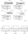
- the controller may begin to draw some vacuum so that a negative pressure is measured and in the absence of an occlusion or partial occlusion of the catheter tip, this will be a nominal reading, representing free-flow of fluid through the catheter, and once the catheter is advanced and engaged with the clot, an increase in the vacuum is observed.
- the controller may set the low limit between -100 rnm-HG and -200 mm-Hg, preferably between -200 mm-HG and - 300 mm- Hg, more preferably between -400 mm-HG and -500 mrn-Hg, and more preferably between -600 mrn-HG and -700 mm-Hg; and it may cause direction of fluid displacement of the pump to be reversed thereby increasing the pressure measured, and unloading a clot.
- Pushability is understood as the transfer of force and/or displacement applied at a proximal portion of a catheter, along a length of the catheter, to a more distal portion of the catheter. The higher the flexural stiffness the greater the pushability.
- distal means further from a clinician in use, closer to a catheter tip in the longitudinal direction, and "proximal” means closer to the clinician.
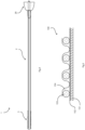
- Fig, 1 illustrates an embodiment of a highly flexible, kink resistant catheter 1.
- the catheter 1 includes a distal portion 3, a proximal portion 2, a central lumen 5 and a reinforcing structure such as a helical support 6 that runs the length of the catheter.
- the proximal portion and/or a transition between the distal portion and the proximal portion can in various embodiments include any of the corresponding features of the catheters described in U.S. Application No. 15/647,763, filed July 12, 2017 , titled "HIGH FLEXIBILITY, KINK RESISTANT CATHETER SHAFT," which is attached in the Appendix.
- the inner tubular layer and/or the outer tubular layer can include PTFE, ePTFE, electrospun PTFE, silicone, latex, TecoThane, nylon, PET, Carbothane (Bionate), SIBS, Tecoflex, Pellethane, PGLA, or Kynar, Polyethylene and cyclic olefin copolymers, PEEK.
- the inner and outer tubular layers ( Fig. 1 ) in at least the distal portion can be formed from a single section of material or a number different sections of similar or different material.
- the outer tubular layer 11 of the distal portion is formed from a polyurethane (e.g. Pellethane 80AE) and the inner tubular layer 5 is formed from ePTFE and/or PTFE.
- the catheter jacket comprises an inner liner 5 and an outer tubular later 11 with a helical support 6.
- the highly flexible distal portion 3 (left side) of the catheter is created by forming corrugations 15 into the outer surface of the outer tubular layer 11.
- the helical support 6 is encapsulated between the corrugations of the outer tubular layer 11 and the outside of the smooth inner tubular layer 5 as shown in Fig. 1 .
- the formation of a corrugated wall structure during bending provides flexibility while reducing the likelihood of kinking.
- the corrugated outer surface can also decrease resistance when the outer surface of the catheter contacts a vessel wall.
- the depth of the corrugations may be tailored to provide a desired variation in stiffness along the length of the catheter as shown in Fig. 2 .
- a parameter "D" is depth of a corrugation and a parameter "W” is the width of a corrugation.
- the width is not the distance from peak to peak, rather it is the effective width of the valley. In effect for many embodiments this is provided during manufacture by tightening a cinch wire around a tubular layer, heat treating, and removing the cinch wire to provide the corrugated surface.
- the width W is approximately the diameter of the cinch wire in this case.
- the depth D is not necessarily uniform because the pressure applied by the cinch wire may vary along the length of the catheter thereby forming deeper indentations in some locations than in others.
- Fig. 2 shows a cross section through a wall of a catheter tip 50, having an inner layer 51, a helical coil support structure 52, an outer layer 53 with a corrugated surface 53.
- the depth A of the corrugations on the left hand side is greater than the depth B on the right hand side.
- the section with the lower corrugation depth B may function as a transition region before a tip (left hand side) with more flexibility.
- the coil is embedded in the jacket; being constrained from movement relative to the surrounding jacket material.
- pitch, or corrugation width variations may be used to control the flexibility locally in the corrugated region.
- flexibility may be set during manufacture by choosing some length of the coil to be embedded in the jacket or to be floating, the region with the floating coil being more flexible. Where the coil is floating it is in the context of the jacket tubular layers being attached in the spaces between corrugation rubs, such as a jacket tubular layer to an inner liner.
- the outer tubular layer can extend at least a length of the highly flexible distal portion or extend beyond the distal portion for some distance along the proximal (midsection) length or extend the entire length of the catheter as shown in Figs. 3 and 4 (which shows the catheter of Fig. 1 in its full length). Extending the outer tubular layer at least some length beyond the highly flexible distal portion of the catheter allows for a controlled stiffness transition between the distal and proximal portions of the catheter and for the formation of a robust joint between the outer tubular layer and any additional outer jacket materials. Again, flexibility may be set during manufacture by choosing some length of the coil to be embedded in the jacket or to be floating, as is the case for any of the embodiments described with reference to Figs. 3 or 4 .
- the membrane can first be positioned over the helical reinforcing structure. On the application of heat, the outer tubular membrane will reflow such that it forms around the helical structure. A tensioned wire can then be wound around the outside of the tubular membrane such that it forces portions of the membrane into the grooves between each loop of the supporting helical structure. The tubular membrane can then be heat set to fix the corrugations in place. After this process the tensioned wire may be unwound leaving the corrugations behind.
- the inner tubular layer can extend into the proximal portion of the catheter to provide an uninterrupted lumen and to join or improve the joint strength between the highly flexible distal portion of the catheter and the proximal portion of the catheter.
- the diameter of the inner tubular layer can be constant (e.g. smooth surface).
- the inner tubular layer may form at least part of or the entirety of the liner as shown in Figure 4 .
- the inner tubular layer can be made from a low friction material such as ePTFE or PTFE.
- the outer tubular layer of at least the distal portion is formed from a polyurethane (e.g. Pellethane 80AE) and the inner tubular layer is formed from an ePTFE and/or PTFE liner. It is necessary to attach these layers together and this is not easily achieved as fluoropolymers do not form strong bonds with other materials.
- a polyurethane e.g. Pellethane 80AE
- the outer or bonding surface of the fluoropolymer(s) may be chemically treated using a sodium-based etching solution such as FluoroEtch.
- the etching solution removes fluorine atoms from the surface of the fluoropolymer and prepares it for bonding.
- the etched fluoropolymer can then be coated with a thin layer of urethane, such as ChronoFlex. On the application of heat, this thin ChronoFlex layer flows and acts to tie the fluoropolymer to a second etched fluoropolymer layer or to a different polymer layer as shown in Fig. 5 . This embeds the coil.
- a thin layer of urethane such as ChronoFlex
- This diagram shows part of the cross-section of a catheter at its distal portion 150.
- This includes a liner 151 of ePTFE or PTFE, a tie layer 152 of urethane or FEP tape or FEP powder.
- a Nitinol TM coil 153 in an outer jacket 154 of ePTFE, or urethane material.
- the nitinol coil 153 is encapsulated between the outer tubular corrugated layer and the smooth inner tubular layer 151.
- the tie layer 151 serves the purpose of attaching the liner 151 to the outer jacket material. If the liner is of ePTFE material then it will need to be etched to strip the fluorine atoms so that it will form a better bond with the tie layer.
- flexibility may be set during manufacture by choosing some length of the coil to be embedded in the jacket or to be floating, as is the case for any of the embodiments described below with reference to Figs. 6 and 7 .
- the ChronoFlex TM tie-layer 152 is so thin it does not cause any significant change in wall thickness.
- An alternative form of tie-layer involves the use of FEP.
- the fluoropolymer may be sputter coated with a FEP powder which under heat and pressure forms a bond between the coated fluoropolymer layer and a second layer.
- An ultra-thin FEP tape may also be used in the same application.
- the helical support is encapsulated between the corrugations of the outer tubular layer and the smooth inner tubular layer as shown in Fig. 5 .
- the inner tubular layer and the outer tubular layer are bonded together in the space between the adjacent loops of the helical support by such mechanisms as a tie-layer.
- the helical support is bonded within the helical channel formed by the corrugated outer tubular layer, i.e., the helical support is molecularly or physically attached to the outer tubular layer.
- the helical support may also be bonded to the outside surface of the smooth inner tubular layer.
- the distal portion of the catheter retains highly flexibility and kink resistance because of the advantages inherent in a corrugated outer structure and using materials of appropriate stiffness and thickness.
- the pitch of the helical support may vary over the length of the catheter to influence the flexural stiffness of the catheter.
- the helical support could have a different pitch at the proximal loops compared to the distal loops.
- the outer tubular layer of the distal portion of the catheter is formed from a fluoropolymer such as ePTFE or PTFE and the outer tubular layer of the proximal portion is formed from a different polymer then achieving a good bond, especially one that resists delamination during tracking, can be difficult. This may be overcome by sandwiching the outer layer of the proximal portion of the catheter between the inner and outer tubular layers of the distal portion of the catheter as shown in Fig. 6 .
- Fig. 6 shows a portion 200 of a catheter, having an inner lumen 201 with a liner, an outer layer 203 of Pellethane 80AE material, and Nitinol coils 206.
- the catheter On the right hand side the catheter has a smooth outer surface 203, and distally in a transition section there are corrugations 204 with a small depth, and more distally deeper corrugations 205 for more flexibility.
- the arrangement of having a transition section between proximal and distal sections may be referred to as a "sandwich arrangement".
- the tubular layers of the distal portion of the catheter can be joined by creating a small slit or window in one tubular layer and pulling a spliced length of the other tubular layer through it as shown in Fig. 7 .
- the helical support is then wound around the outside of these layers thus keeping them together.
- Fig. 7 shows a catheter section 250 with a proximal end 251, a transition section 252, and a distal tip 253, and a spliced proximal layer 260 with a window 261.
- the helical support is physically attached by being constrained or embedded in the catheter wall to move with its surrounding wall material. Such embedding might be achieved at an interface between the coil and solely the jacket material, or combination of an interface of the jacket material and the inner liner.
- the embedding can be achieved by a very tight fit between the coil and the surrounding material. Generally, there is no gap between the surrounding wall material and the coil. Due to the three-dimensional geometry of the coil, when within a surrounding material, it is unable to move independently.
- the material may be moulded around the coil, there is no play between the coil and jacket, meaning it cannot move independently. That is to say, the coil is immovable without concurrent movement or deformation the surrounding jacket material.
- the coil may be floating, that is to say there is not a tight fit between the material in the jacket and the helical coil.
- the width of the corrugate is between 5% and 49% of the pitch of the corrugate, and more preferably the width of the corrugate is between 15% and 45% of the pitch of the corrugate.
- the width of the corrugate is between 20% and 45% of the pitch of corrugate.
- the width of the corrugate is at least 10% of the jacket thickness.
- the width of the corrugate is at least 20% of the jacket thickness.
- the width of the corrugate it at least 60% of the jacket thickness.
- the width of the corrugate it at least 60% of the wall thickness and the depth of the corrugate is at least 70% of the wall thickness.
- the ratio of the width of the corrugate to the depth of the corrugate is at least 0.5 in at least one region of the catheter.
- the coil may be either embedded or floating in some or all regions of the catheter, unless stated otherwise.
- a catheter with a highly flexible distal tip to ensure that a smooth transition in flexural stiffness and pushability is achieved between the flexible distal portion and the proximal portion of the catheter, which may be of more conventional construction.
- a smooth transition prevents areas of stress and strain concentration within the catheter shaft. Such areas have potential for kinking of the catheter, delamination of layers of material, and/or of damage to key bonds within the catheter.
- Bench testing demonstrates the large difference between the stiffness of a conventional catheter tip design and a highly flexible corrugated design. Smoothly bridging of this gap presents a technical challenge.
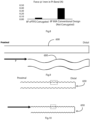
- Fig. 8 shows force measured at a 1 mm displacement in a 3-point bend test of a conventional catheter design (0. 80A urethane jacket over a 0.005in NiTi coil 0.018in (0.45 mm) pitch over on a 0.001in (0.025mm) PTFE Liner), and highly flexible corrugated ePTFE design (inner and outer 0.002in (0.05 mm) wall ePTFE 0.9g/cm 3 density, with a 0.005 in (0.125 mm) NiTi coil, 0.018 in (0.45 mm) pitch.
- pushability is understood as the transfer of force and/or displacement applied at a proximal portion of a catheter, across a length of the catheter, to a more distal portion.
- Catheter flexibility may limit the transfer of a displacement applied at a proximal portion of the catheter to a distal portion of the catheter. This implies a portion of the displacement is absorbed through global deformation of the catheter as shown in Fig. 9.
- Fig. 9 shows behaviour of a conventional catheter under compression when pushed against restriction. In this instance the length of the catheter 600 has not changed. In general, it is this type of shortening which occurs in catheters of conventional construction.
- Fig. 10 shows behaviour of a corrugated catheter 650 under compression when pushed against restriction.
- the deformation may be accommodated by the catheter wall.
- the inner and or outer tubular layers of the catheter can deform locally, particularly in the recess meaning the overall length is reduced. Some of the global deformation of the catheter as shown in Fig. 9 would also be expected.
- This soft compressive behaviour is advantageous at the distal tip as the catheter tip is limited in its ability to move forward causing vessel damage or dissection.
- some increased pushability in the proximal portion of the tip may be preferable to allow the physician to navigate the catheter distally and proximally as intended.
- one or more regions of varying pushability and flexibility are present within the catheter tip comprised of one or more of the regions of a rib and recess construction.
- Fig. 11 shows in a catheter 700 use of progressively more flexible or less pushable sections of catheter wall 701 within the distal tip, distally of a proximal portion 702. In one configuration the most flexible region is on the distal tip of the catheter.
- regions of increased/decreased pushability/flexural stiffness are achieved by a number of features such as embedding of the helical support, alterations to the inner and outer tubular layers (wherein the helical support may or may not be floating between the inner and outer tubular layers), or the use of an in-fill material.
- the change in the stiffness or pushability via the transition region may be gradual change or via multiple steps. Where it is stepped or gradually changed it may be achieved by having a particular tubular layer terminated, or by a change to the degree of corrugation or a change in material.
- the helical support is embedded by being bonded to the outer jacket, of for example ePTFE material. This has the effect of stiffening the catheter wall construction, when compared to a floating helical support, thus reducing the flexibility and increasing the pushability.
- a catheter portion 750 in a catheter portion 750 the helical support 752 is embedded in a matrix 753 of continuous porous flexible material such as ePTFE.
- the outer wall has corrugated surface, as shown in Fig. 12 .
- An inner tubular layer, or liner 751, as shown in Fig. 12 may not be required.
- ePTFE provides a very soft flexible material in the catheter construction it is also compressible due to its porosity. Furthermore, when used as a thin tubular layer which deforms easily locally, macro pushability can be compromised if an area of the catheter becomes impeded particularly if the distal tip meets a resistance.
- an incompressible flexible material may be used for embedding instead of a porous material such as ePTFE. This means it can accommodate deformation more readily than materials which are not porous.
- the corrugations allow localised deformation, while a region of continuous incompressible material ensures the efficient transfer of axial force and displacement along the length of the catheter.
- a region of continuous incompressible material ensures the efficient transfer of axial force and displacement along the length of the catheter.
- the inner tubular layer is comprised of ePTFE.
- the helical support is transposed from the inner liner such that it is not exposed to the liner. This is to prevent movement or debonding of the helical support, and to prevent it placing local stress or strain on the liner of the catheter.
- the corrugation geometry may be of semi-circular, U-shaped groove, V-shaped, or square groove.
- the width of the corrugate at the surface of the catheter is at least 5% of the wall thickness of the wall.
- the width of the corrugate at the surface of the catheter is at least 10% of the wall thickness at the wall.
- the width of the corrugate at the surface of the catheter is at least 30% of the wall thickness at the wall.
- the corrugate depth is between 5% and 95% of the catheter wall thickness. In one configuration the corrugate depth is at least 20% of the catheter wall thickness in at least one section of the catheter.
- the corrugate depth varies along the corrugated region of the catheter from a larger depth distally to smaller depth proximally.
- the corrugate width varies along the corrugated region of the catheter from a larger depth distally to smaller depth proximally.
- the corrugate depth varies from a larger depth distally to smaller depth proximally, while the width is substantially constant along the length of the corrugated section of the catheter.
- the corrugate represents the impression of a circular helical wire wound from a depth and width of no impression, i.e. no corrugate, to a depth of at least 50% of the wall thickness. It should be appreciated in that instance that the width of the corrugate is varying from 0 to a maximum width equivalent to the diameter of the helical wire, or impression which remains following removal of the helical wire.
- a tensile force on the wound cinch helical wire is required to create the corrugations.
- a 0.005in 304 Stainless Steel circular cross section wire at 1N tension wound at a force 1N, on a 0.006in wall thickness 80A jacket with an ID of 0.088in will achieve a 10-20% depth of corrugation.
- Increasing the tension to 1N tension wound at a force 7N will achieve a 40-70% depth of corrugation.
- Varying levels of force will induce different degrees of corrugation.
- corrugations of high depth D as shown in Fig. 1 will allow the catheter section to flex at a relatively low force. This is because the global bending of the catheter is actually concentrated within the recess of the corrugate.
- This bottoming-out means the catheter shaft has a lower limit of bend-radius which it can achieve via deformation within the recess. Further bending deformation beyond the bottoming-out limit is achievable but is not accommodated by deformation at the recess of the corrugation; it is accommodated by pressing adjacent corrugations against one another. This is generally at a very high force compared to the deformation which occurs at lower bend radii while the deformation is focused in the recess.
- the width of the corrugate should be controlled so as to be large enough to accommodate sufficient deformation within the recess to reach the desired lower limit of bend-radius at relatively low force of bending. This is important as physicians generally wish to be able to navigate catheters at low forces so that the potential for vessel damage is reduced, and the catheters are not deforming the vessels in order to travel forward.
- the width and depth of the corrugation contribute to the flexural stiffness of the catheter, the width can dominate the lower limit of bend-radius to which the catheter can deform. Accordingly, a larger corrugate width enables a lower bend radius at a low force of bending.
- the width of the corrugate should be of a minimum value relative to the pitch and or wall thickness.
- the width of the corrugate is no more than 50% of the pitch of the corrugate (same as the pitch of the helical support).
- the width of the corrugate is between 5% and 49% of the pitch of the corrugate. More preferably the width of the corrugate is between 15% and 45% of the corrugate. More preferably the width of the corrugate is between 20% and 45% of the corrugate.
- the width of the corrugate is at least 10% of the wall thickness. Preferably the width of the corrugate is at least 20% of the wall thickness. In one embodiment at the most distal section of the tip the width of the corrugate it at least 60% of the wall thickness.
- the width of the corrugate it at least 60% of the wall thickness and the depth of the corrugate is at least 70% of the wall thickness.
- the corrugate represents the impression of a circular helical wire wound from a depth and width of no impression, i.e. no corrugate, to a depth of at least 70% of the wall thickness.
- the inner tubular layer terminates in a region proximal to the distal end of the catheter. This will further reduce the stiffness of the catheter for a corrugated or uncorrugated configuration.
- the region without a liner may be tacky.
- the region of inner lumen of the catheter without a liner has hydrophilic or hydrophobic coating to improve lubricity. This is shown in Fig. 13 for a catheter portion 760 having a helical support 761 embedded in an outer jacket 762, and in which an inner liner 763 extends for part of this length but terminates before the distal end (left side).
- the un-lined section is at least 1cm in length, preferably at least 2 cm in length.
- the termination of the liner is advantageous in allowing a more flexible section of the catheter. However, this can also form a sudden change in flexural stiffness and potential location for kinking or high stress or strain. This may be managed using a change in corrugation parameters, or by skiving the liner. In another embodiment, the termination of the liner is a skive, or angular cut.
- a section of the un-lined jacket material adjacent to the liner proximally is less corrugated than the section of unlined jacket distally and proximally. This may be achieved by decreasing the depth of the corrugation.
- a corrugated section of the lined jacket adjacent to the unlined jacket has a longer pitch than the section of unlined jacket distally and proximally.
- the helical support is transposed from the inner liner such that it is not exposed to the inner lumen of the catheter as shown in Fig. 14 , having a helical support 771 in an outer jacket 772. This is to prevent pop-out the helical support into the catheter lumen during bend of the catheter.
- the distance from the inner lumen to the helical support is at least 0.005mm.
- a catheter portion 780 there is a helical support 781, and an outer jacket 782 and an inner liner 783.
- the outer jacket 783 has a proximal part 784 without corrugations, distal part 785 with corrugations.
- the inner liner 783 terminates proximally of the distal end at 786.
- all sections of the jacket are of the same material durometer.
- the material is urethane of durometer 80A.
- more proximal jackets are of a stiffer urethane or pebax are present.
- the liner is comprised of ePTFE. In a more proximal section of the shaft, the liner may transition to PTFE. In one embodiment this transition takes place in a more stiff durometer material than that of the jacket of the corrugated distal tip.
- a catheter portion 800 has a liner 751, a helical support 752, and an outer jacket 753 as for the catheter portion 750.
- an outer tubular layer 801 added to the outside of the corrugated structure which embeds the helical support to further increase the stiffness of a section of the catheter proximally of the distal end, as shown in Fig. 16 .
- This layer may be of the same or different material as the material used to encapsulate the helical support. Materials of higher stiffness such as PET or Nylon pr PEEK or other polymer can be used in this instance without significantly adding to the profile.
- a layer of PET is added which has a thickness of 0.05 mm or less, preferably 0.025 or less, and more preferably 0.0125 mm or less.
- FIG. 18 shows a catheter portion 850 with a liner 851, a coil 852 and inner and outer tubular layers 853 and 854 respectively and in-fill for increased stiffness
- the material is used only to partially fill the space around the helical support as shown in Fig. 18 .
- the in-fill material completely fills the helical channel around the helical support between the inner and outer tubular layers.
- the in-fill material is melted to form a layer of material on all surfaces within the helical channel.
- the outer and inner tubular layer are comprised of ePTFE or PTFE, and the in-fill material is PET, PEEK or FEP
- the helical channel may be formed using a helically wound wire (cinch wire) placed temporarily on the outside of the outer tubular layer.
- a helically wound wire cinch wire
- the construction may then be heated such that the in-fill layer melts to flow between the helical support, the outer tubular layer, and the inner tubular layer.
- the corrugate configuration is maintained, and an adhesive chemical bond is achieved between the components via the in-fill material.
- the in-fill material may be a polyurethane, pebax, PET, silicone, latex, TecoThane, Nylon, PET, Carbothane, SIBS, Tecoflex, Pellethane, PGLA or Kynar, Polyethylene and cyclic olefin copolymers, PEEK.
- the inner tubular layer and outer tubular layer of ePTFE are bonded to one another via sintering.
- sintering it must be appreciated that in the case of a fluoropolymer, and in particular ePTFE or PTFE for use as the inner and outer tubular layers, the temperature required for the sintering can exceed 500°C. In this instance it may be preferable to use materials for in-fill with a high processing and degradation temperatures such as PET, FEP, or PEEK. Other materials such as urethane or pebax will degrade at lower temperature and are not suitable.
- PET is a relatively stiff material it can be introduced in small volumes to stiffen the corrugate structure without significant impact on catheter profile or completely filling of the helical channel. This may provide regions of floating and of embedded coil.
- an increase in the pushability or stiffness is achieved by changing the thickness of one or both of the tubular layers.
- An increase in thickness increases the intrinsic stiffness of the wall. It also means a reduction in the available space for localised material bending and deformation. Therefore, the flexibility may be reduced. Furthermore, as the thickness increases the axial cross-sectional area along the axis of transmission of force and displacement along the catheter increases.
- both the inner and outer tubular layer thickness are increased, as shown in Fig. 19 for the catheter portion 950 as compared to the catheter portion 900.
- the catheter portion 900 there is an inner liner 901, a coil 902 and an outer tubular layer 903.
- the catheter portion 950 there is a thicker inner liner 951, a coil 952, and a thicker outer tubular layer 953.
- the inner tubular layer thickness alone is increased.
- the outer tubular layer thickness alone is increased.
- a catheter portion 1000 has a liner 1001, an outer jacket layer 1002 underneath a coil 1005, and two layers 1003 and 1004 outside the coil 1005.
- the total inner tubular layer wall thickness may be increased by the addition of one or more layers. These layers may be of the same or different materials. In the case of ePTFE, the combined thickness of the inner tubular layers in an unconstrained configuration may be between 0.025 mm to 0.3 mm, preferably between 0.05 mm and 0.2 mm.
- the inner and outer tubular layers are comprised of multiple layers of ePTFE, wherein there is at least one layer between an outer tubular layer and an inner tubular layer.
- the total thickness of (for example, ePTFE) tubular layers which are comprised of one or more layers may be between 0.025 mm to 0.3 mm, preferably between 0.05 mm and 0.2 mm.
- the density of the material (again, such as ePTFE) may be approximately 0.9g/cm 3 . Increasing or decreasing the density of the material will necessitate a bigger or smaller wall thickness to achieve the same effect.
- the inner tubular layer thickness is constant along the length of the tip, but the outer tubular layer thickness is larger in at least one region. In another embodiment the outer tubular layer thickness is increased proximally at least once along the length of the catheter tip.
- Fig. 21 In order to achieve a controlled change in stiffness of the distal tip, multiple layers may be overlapped to achieve a precise level of stiffness as shown in Fig. 21 in which an additional outer layer 1010 is present for part of this catheter portion.
- This principle may be used for any number of layers, to achieve a desired variation in stiffness.
- single thicker layers may be used proximally, connected to a thinner layer more distally to achieve the same effect.
- the tip has one outer tubular layer of 0.025 mm to 0.075 mm across the length of the tip.
- a second additional outer tubular layer of thickness 0.025 mm to 0.075 mm is present in a region more proximally.
- a third additional outer tubular layer of thickness 0.025 to 0.075 mm is present in a region even more proximally.
- a fourth additional layer of thickness 0.025 to 0.075 mm is present in a region even more proximally.
- the distal tip comprises an outer tubular layer of 0.05 mm across the length of the tip.
- a second additional outer tubular layer of thickness 0.05 mm is present in a region more proximally.
- a third additional outer tubular layer of thickness 0.05 mm is present in a region even more proximally.
- a fourth additional layer of thickness 0.05 mm is present in a region even more proximally.
- the tubular layers are bonded to one another.
- the bond may be present across the entire interface of the tubular layers.
- the bond may only be present at recesses of the corrugations, in the area where the inner and outer tubular layer are in contact.
- the bond is present between the layers at the rib and recess regions of the corrugations.
- the material of the inner or outer tubular layer may be changed to one with a higher stiffness to increase the stiffness of the wall.
- tubular layers may be present locally following bonding of inner and outer tubular layers, or their constituent layers, due to the use of local compression (pressure) to ensure a strong bond between tubular layers.
- local compression pressure
- This localised compression may reduce the wall thickness in that area.
- 8F catheter samples of inner diameter 0.088in were built and tested in a Three Point Bend Test.
- the force at a 1mm displacement was measured using a 50N Load Cell on a Zwick Roel tensile test machine.
- the distance between the supports was 20mm. Clear changes in stiffness were achievable using the various configurations outlined above.
- Fig. 22 shows results of 3-point bend tests to evaluate stiffness of various embodiments described above.
- the distal tip has a minimum length of its most flexible section such that the catheter tip will deflect or absorb deformation rather than causing vessel damage.
- the distal and flexible sections of the catheter of corrugate rib and recess design is a minimum of 1cm in length and is comprised of inner and outer tubular layers in a corrugate configuration, with a floating helical support within a helical channel.
- the force in 3-point bend test for a span of 20mm, at 1mm deflection, should not exceed 0.1N.
- the distal-most end 1050 of the distal portion is finished by inverting an inner tubular layer 1051 over the helical support to form a continuous element.
- a distal end 1060 in a distal end 1060 the softness of the distal tip end is improved by extending inner and outer tubular layers 1061 and 1062 beyond the last coil of the helical support.
- an inner tubular layer 1071 is inverted at the distal end 1072 to return as a continuous element.
- Inner and outer tubular layer are comprised of the same piece of material and are continuous.
- An extension of ePTFE at the end 1072 of the corrugated section is present to improve tip softness.
- an extension beyond the last coil is between 0.5 and 5.0 mm. More preferably the extension beyond the last coil is between 1.0 and 0.3 mm.
- the distal portion 1070 also has an outer tubular layer 1073 terminating before the distal end 1072, and a concentric further outer tubular layer 1074 around the layer 1073 for part of the length of the layer 1073. This staggered overlapping arrangement provides a transition portion with stepped changes in flexural stiffness.
- Fig. 25B shows a catheter distal portion 1080 with an inner liner 1081 which extends out at the distal tip to form an extension. In this case there are also overlapping staggered outer tubular layers 1083 and 1084.
- two or more layers are achieved by using the same piece of material inverted and returned along the length or a portion of the catheter.
- two pieces of ePTFE are used to achieve one inner tubular layer, and three outer corrugated tubular layers.
- catheter 1080 additional layers are added discretely.
- a combination of inverted continuous layers and discrete layers is used.
- the proximal portion of the catheter shown un-corrugated
- PTFE material is a relatively stiff material compared to eTPFE and so is therefore preferable to avoid the use of PTFE as an inner tubular layer (liner) particularly in areas which will be subject to significant bending during passage through tortuous vessels.
- an inner tubular layer is of ePTFE material and this extends along the entire length of the catheter including a distal end 1103, where it is bent back to be continuous with the outer tubular layer.
- the inner tubular layer is ePTFE in a distal portion and PTFE in a more proximal portion of the catheter as shown in Fig. 27 for a catheter 1150 having a proximal end 1151, an intermediate portion 1152, a distal portion 1153.
- a transition region 1154 in which the outer jacket a layer is merged into and joined with an outer jacket of PTFE material in the intermediate portion and the transition region.
- the transition from ePTFE to PTFE may be achieved by a "butt" joint, in which the inner tubular layers of PTFE and ePTFE are in contact without overlap.
- a transition from inner tubular layer of ePTFE to PTFE occurs in a region of the catheter which is not subject to significant bending during use.
- the device dimensions are suitable for placement in the neurovasculature, including M2, M1 and distal internal carotid arteries.
- the transition from ePTFE to PTFE occurs proximal to the petrous segment of the ICA.
- the transition from an ePTFE to PTFE inner tubular layer occurs between 3 and 40cm from the distal end of the catheter, preferably between 5 and 30cm from the distal end, and more preferably at least 10cm from the distal end.
- the transition from inner tubular layer of ePTFE to PTFE occurs in a region proximal to a region of the catheter of rib and corrugation recess.
- the transition from inner tubular layer of ePTFE to PTFE occurs proximal to the most flexible region of a rib and recess corrugate design, but still within a region of stiffer rib and recess corrugate design.
- the proximal region of rib and recess corrugate has an outer tubular layer comprised of a polymer material, as shown in Fig. 28 .
- the polymer material is a urethane or pebax.
- the polymer material is 80A urethane.
- Fig. 28 shows a catheter 1200 having a proximal end 1201, an intermediate portion 1202, a distal portion 1203, and a transition region 1204.
- An ePTFE inner tubular layer (liner) 1207 transitions to a PTFE jacket 1205 in the intermediate portion within a corrugated section of the distal tip.
- a lap joint is used in which the PTFE tubular layer 1208 is concentric within the ePTFE tubular layer 1207.
- transition from ePTFE to PTFE may be achieved via a "lap" joint wherein there is overlap of the tubular layers of ePTFE and PTFE.
- the overlap between the PTFE and ePTFE is between 1mm and 30mm in length. The use of an overlap increases the area of interface for bonding thus improving the bond strength.
- a catheter 1250 has a proximal end 1251, and intermediate portion 1252, and a distal portion 1253.
- An inner liner 1260 is bent over at the distal end to form part of the outer jacket of the distal portion 1253.
- the inner liner 1260 is within a tube of PTFE material 1261 with an overlap length of at least 2mm, preferably at least 5mm.
- the tubular layer 1261 extends proximally within a jacket material 1262 in the intermediate portion 1252.
- the distal flexible tip length is at least 10 cm, and the un-lined distal section is at least 3cm in length.
- the device is suitable for placement in the peripheral vasculature, the
- Aspiration Device including the Catheter.
- a catheter of any example may be used for example for thrombectomy.
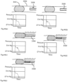
- Fig. 32 The prior art setup of balloon guide catheter in a thrombectomy procedure is shown schematically in Fig. 32 , with a balloon 1300 and a tip 1301.
- Balloon guide catheters for use in thrombectomy procedures must facilitate the insertion of a microcatheter, and distal access catheter.
- the balloon guide In order to do this, the balloon guide must have an inner diameter in the range of 5F or greater. Additionally, the catheter typically has an outer diameter in the range of 8F or 9F.
- the tip of the balloon guide catheter should be as close to the clot as possible. This reduces the distance over which the clot must be dragged from the target vessel to the location of the balloon guide catheter tip. It may also enable the physician to directly aspirate the clot locally as the tip of the catheter can now engage the clot.
- remote aspiration of the clot is being performed using balloon guide catheters, while the balloon is inflated.
- Remote aspiration is a procedure in which the clot is aspirated without contact of the catheter tip with the clot. This works particularly well in a closed system where alternative flow pathways are not present. The success of this technique is often limited by the fact that the tip of the catheter can be a long distance from the clot.
- a balloon catheter whether used for PTA or embolic protection, is typically of a dual lumen, double layer construction along the length proximal to the balloon. This ensures there are two lumens; one for the passage of guide wires, catheters, or fluids, and one lumen for inflation. This dual layer construction is not always as flexible as desired, and is prone to kinking.
- a balloon guide catheter which can provide flow arrest, but which also incorporates a very flexible distal portion which can track through a tortuous vessel, such as the distal ICA or as far as the MI or other vasculature.
- a shaft or section with enhanced flexibility compared to the proximal section is present distal to the balloon of a balloon catheter.
- This flexible section enables the tip of the balloon to be placed more distally in the vasculature.
- This section of enhanced flexibility may be comprised of the types described in U.S. Application No. 15/647763, filed July 12,2017 , titled “HIGH FLEXIBILITY, KINK RESISTANT CATHETER SHAFT," and U.S. Provisional No. 62/599560, filed December 15, 2017 , titled "HIGH FLEXIBILITY, KINK RESISTANT CATHETER SHAFT" (both included in the Appendix), corrugate construction or other design.
- This device may be designed so that the distal tip is flexible enough to reach and touch the clot for vacuum aspiration.
- the part which is distal of the flow restrictor (such as the balloon) includes the distal portion and preferably at least some of the transition portion. There may also be some of the transition portion proximally of the flow restrictor.
- the length of this flexible section may vary such that it can reach specific anatomical locations, such as the distal internal carotid artery, terminus of the internal carotid artery, proximal MI, distal MI, proximal M2, distal M2, basilar, or vertebral vessels. This length may also help ensure that that while the tip of the catheter can reach the target vessel, the balloon does not pass the cavernous, or petrous segment of the ICA. Inflation of the balloon beyond these segments can cause vessel damage.
- the length of the flexible section may be between 1cmn and 20cm, preferably between 3cm and 15cm.
- the outer diameter of this flexible tip may differ from the outer diameter of the proximal section of the catheter.
- the distal section has a larger diameter than the proximal section.
- the outer diameter has a diameter smaller than the diameter of the proximal section of the catheter. Variations such as a taper in the diameter of the distal section may also be used. Differing diameter distal sections can help to ensure access to specific vessels beyond the area to land the balloon.
- Fig. 33 shows a device 350 with a flexible distal catheter tip 1351 extending from a balloon 1352, and proximally of which there is a catheter main section 1353 extending from a Y-piece 1354.
- Fig. 10 shows the balloon 352 inner layer inflation lumen 1360 and the balloon outer layer inflation lumen 1361.
- the outer layer of balloon inflation lumen may of enhanced flexibility while the inner layer of the balloon inflation lumen may be of a conventional construction comprising a single layer material, braided extrusion, coiled extrusion or other construction. These layers are shown schematically in Fig. 34 , inner layer 1360 and outer layer 1361. In this way the pushability of the catheter may be maintained by the inner layer, while the outer layer mitigates compromise in terms of flexibility. Furthermore this construction will help to prevent kinking, since mechanics dictate that as the ratio of the inner diameter to the outer diameter of a tube increases, kink resistance is reduced. Use of the enhanced flexibility construction for the outer layer, traditionally more prone to kinking will solve this issue.
- a balloon catheter of dual layer construction comprises both inner and outer layer of the balloon inflation lumen of the enhanced flexibility construction. This will represent an ultra-flexible and kink resistant balloon catheter.
- the proximal section may utilise other constructions to inflate the balloon such as a single lumen design with a vent hole and teak proof seal, a coaxial lumen or other design.
- a balloon guide catheter with a long distal tip capable of reaching a clot may be used as a thrombectomy device as follows:
- enhanced catheter shaft flexibility and kink resistance may be achieved without additional helical wire support, but instead using a simple tubular construction with a corrugate architecture.
- the corrugations may be defined as adjacent circular depressions in the wall thickness of the tube, or as a continuous helical depression as shown in Figs. 35 and 36 respectively.
- the tip has an outer layer 1400 with corrugations 1401 ( Fig. 35 ) and an outer layer 1450 with more shallow corrugations for desired flexibility.
- the device may be designed so that the distal tip is flexible enough to reach and touch a clot for vacuum aspiration.
- the typical target vessels are the M1, M2, M3, distal ICA.
- the distal tip should be long enough to reach the target vessel, while also ensuring that the balloon does not pass the petrous segment of the internal carotid artery (known as C2). This is because the vessels and surrounding tissue beyond the petrous segment are prone to damage which can have catastrophic consequences.
- the length of the flexible section may be between 1cm and 20cm, preferably between 3cm and 20cm.
- Fig. 37 left image shows an Angiogram demonstrating the external carotid, common carotid and internal carotid artery (ICA), including the C1 and C2 segments
- right image shows acceptable positioning of the balloon (2282, in a catheter 2280 proximal of a distal end 2281. It should not be inflated past the C2 segment. The distal tip length of the catheter should be long enough to reach the clot while ensuring safe position within or proximal to the C2 segment of the ICA.
- ICA external carotid, common carotid and internal carotid artery
- the proximal shaft must serve two functions and have at least two lumens; one for balloon inflation and a main lumen for delivery of fluids and devices, and for aspiration.
- the flexible tip only requires one lumen, therefore has potential to have a larger lumen than the proximal section.
- the inner diameter of the flexible tip is the same inner diameter as the proximal shaft.
- proximal and distal shaft have the same outer diameter, and the proximal shaft has two concentric lumens, in which the central lumen diameter is less than that of the flexible distal tip as shown in Fig. 38 .
- This drawing shows a balloon guide catheter 2300 with a flexible corrugated distal tip 2302 and a balloon 2301. In this incidence the inner diameter of a proximal shaft lumen 2303 is less than that of the flexible corrugated distal tip 2302.
- the proximal and distal shafts have the same outer diameter.
- the inner diameter of the proximal shaft is the same as that of the flexible distal tip.
- the outer diameter of the distal tip is smaller than that of the proximal shaft.
- the distal tip inner diameter may be the same as, or smaller than, the inner diameter of the proximal shaft.
- Fig. 39 shows a catheter 1400 with a balloon 2401 and a distal portion 2402 having a smaller outer diameter than the proximal portion 2403.
- the distal tip is comprised of a flexible corrugate section distally, and a non-corrugated section proximally.
- Fig. 40 shows a catheter 1500 with a non-corrugated proximal region 2501 of the distal region 2502.
- a radiopaque marker is present at the distal end of the flexible distal tip. Markers are also present immediately distal and or proximal to the balloon to define its location. An additional intermediate distal marker may be present within the distal tip to define a proximal region of increased stiffness unsuitable for placement in distal to the C2 segment of the ICA.
- the balloon catheter is suitable for use via direct carotid access.
- a shorter proximal shaft will improve ergonomics for the physician.
- the length of the catheter shaft proximal to the balloon does not exceed 40cm, and preferably does not exceed 30 cm.
- the embodiments described above enable the physician to place larger bore catheters more distally than has been possible using conventional catheter technology. However, it may not be possible to place a larger catheter in the target vessel due to the vessel diameter being smaller than the catheter itself. In this instance a larger catheter may be used to achieve flow restriction.
- additional vessels are present which perfuse the treatment area.
- proximal occlusion using a balloon guide catheter placed in the ICA does not prevent inflow to the target treatment site.
- This is also a problem in posterior stroke where there are two significant inflow vessels (left vertebral artery and right vertebral artery), and the target treatment site is the basilar artery or posterior communicating artery.
- a system is comprised of a "mother" and "daughter" catheter, in which significant flow restriction, or flow arrest, may be achieved by placing or wedging a large bore highly flexible mother catheter in a vessel location proximal to the target treatment site. A smaller daughter catheter may then be passed through the parent catheter to the treatment site. In this instance a proximal balloon for flow restriction is not required. Near occlusion of the vessel, without wedging the catheter, will dramatically reduce flow also. This is shown in Fig. 42 , in which there is a large catheter 2702 and a smaller catheter 2703 for aspiration of a clot 2701. Large bore highly flexible catheters can enable the most distal flow arrest possible.
- flow restriction using a larger bore catheter may also be advantageous.
- additional embolization procedures are often used occlude adjacent non-target vessels.
- Non-target embolization can cause non-target vessel occlusion, or the delivery of a drug to non-target tissue. This may be avoided if a larger bore highly flexible catheter is placed distally in the vessel feeding the target region of delivery of the embolic such that the catheter tip is wedged. Upon injection of the embolic, the wedged condition prevents retrograde flow of the embolic, thus preventing non-target embolization.
- the pressure gradient within the vessel is a reflection of the proximal injection pressure, rather than the hemodynamic pressure, giving the physician full control of the delivery of the embolic.
- Fig. 43 shows such a configuration, in a catheter 2800 having a distal portion 2801
- Left shows the use of a small catheter unable to reach a distal target vessel (right side vessel) during delivery of a drug or embolic and the resulting undesired delivery to a non-target vessel (top left vessel)
- the right hand diagram shows the use of a method wherein a highly flexible large diameter catheter is chosen to effectively occlude the target vessel, and can be placed beyond the non-target vessel, so delivery of the embolic only occurs to the target vessel. It is preferable that the catheter is wedged in the target vessel.
- embolization procedures means that often, only microcatheters are capable of entering the vessels today. This limits the type of embolic which can be used (e.g. 018 microcoils may need to be used where larger 035 coils or a plug would e preferred, or the desired particle becomes clogged in the only microcatheter capable of entering the vessel).
- the technical success of these procedures is also limited by the inability to place larger support catheters distally.
Landscapes
- Health & Medical Sciences (AREA)
- Life Sciences & Earth Sciences (AREA)
- Heart & Thoracic Surgery (AREA)
- Veterinary Medicine (AREA)
- Public Health (AREA)
- General Health & Medical Sciences (AREA)
- Animal Behavior & Ethology (AREA)
- Biomedical Technology (AREA)
- Engineering & Computer Science (AREA)
- Hematology (AREA)
- Anesthesiology (AREA)
- Pulmonology (AREA)
- Biophysics (AREA)
- Vascular Medicine (AREA)
- Surgery (AREA)
- Nuclear Medicine, Radiotherapy & Molecular Imaging (AREA)
- Orthopedic Medicine & Surgery (AREA)
- Medical Informatics (AREA)
- Molecular Biology (AREA)
- Chemical & Material Sciences (AREA)
- Chemical Kinetics & Catalysis (AREA)
- Epidemiology (AREA)
- Media Introduction/Drainage Providing Device (AREA)
- Infusion, Injection, And Reservoir Apparatuses (AREA)
Applications Claiming Priority (6)
| Application Number | Priority Date | Filing Date | Title |
|---|---|---|---|
| US201762599560P | 2017-12-15 | 2017-12-15 | |
| US201762599573P | 2017-12-15 | 2017-12-15 | |
| US201862616188P | 2018-01-11 | 2018-01-11 | |
| EP21177317.1A EP3925638B1 (de) | 2017-12-15 | 2018-12-14 | Verbesserte katheter |
| PCT/EP2018/085064 WO2019115809A1 (en) | 2017-12-15 | 2018-12-14 | Improved catheters and devices and systems incorporating such catheters |
| EP18830199.8A EP3723821B1 (de) | 2017-12-15 | 2018-12-14 | Verbesserte katheter und vorrichtungen und systeme mit solchen kathetern |
Related Parent Applications (3)
| Application Number | Title | Priority Date | Filing Date |
|---|---|---|---|
| EP21177317.1A Division EP3925638B1 (de) | 2017-12-15 | 2018-12-14 | Verbesserte katheter |
| EP21177317.1A Division-Into EP3925638B1 (de) | 2017-12-15 | 2018-12-14 | Verbesserte katheter |
| EP18830199.8A Division EP3723821B1 (de) | 2017-12-15 | 2018-12-14 | Verbesserte katheter und vorrichtungen und systeme mit solchen kathetern |
Publications (2)
| Publication Number | Publication Date |
|---|---|
| EP4512453A2 true EP4512453A2 (de) | 2025-02-26 |
| EP4512453A3 EP4512453A3 (de) | 2025-05-14 |
Family
ID=64959302
Family Applications (3)
| Application Number | Title | Priority Date | Filing Date |
|---|---|---|---|
| EP25151200.0A Pending EP4512453A3 (de) | 2017-12-15 | 2018-12-14 | Verbesserte katheter sowie vorrichtungen und systeme mit solchen kathetern |
| EP18830199.8A Active EP3723821B1 (de) | 2017-12-15 | 2018-12-14 | Verbesserte katheter und vorrichtungen und systeme mit solchen kathetern |
| EP21177317.1A Active EP3925638B1 (de) | 2017-12-15 | 2018-12-14 | Verbesserte katheter |
Family Applications After (2)
| Application Number | Title | Priority Date | Filing Date |
|---|---|---|---|
| EP18830199.8A Active EP3723821B1 (de) | 2017-12-15 | 2018-12-14 | Verbesserte katheter und vorrichtungen und systeme mit solchen kathetern |
| EP21177317.1A Active EP3925638B1 (de) | 2017-12-15 | 2018-12-14 | Verbesserte katheter |
Country Status (6)
| Country | Link |
|---|---|
| US (3) | US11197977B2 (de) |
| EP (3) | EP4512453A3 (de) |
| JP (3) | JP7274485B2 (de) |
| CN (2) | CN111465420B (de) |
| ES (1) | ES2894768T3 (de) |
| WO (1) | WO2019115809A1 (de) |
Families Citing this family (43)
| Publication number | Priority date | Publication date | Assignee | Title |
|---|---|---|---|---|
| US11660420B2 (en) | 2018-09-17 | 2023-05-30 | Seigla Medical, Inc. | Catheters and related devices and methods of manufacture |
| EP3247444B1 (de) | 2015-01-20 | 2023-03-29 | Q'Apel Medical, Inc. | Röhrenförmige strukturen mit variabler unterstützung |
| WO2018022813A1 (en) | 2016-07-27 | 2018-02-01 | Q'apel Medical, Llc | Tubular structures with variable support |
| US11224458B2 (en) | 2017-04-10 | 2022-01-18 | The Regents Of The University Of Michigan | Hydrodynamic vortex aspiration catheter |
| CN111031943B (zh) | 2017-04-10 | 2024-09-27 | 密歇根大学董事会 | 流体动力涡旋抽吸导管 |
| US10531883B1 (en) | 2018-07-20 | 2020-01-14 | Syntheon 2.0, LLC | Aspiration thrombectomy system and methods for thrombus removal with aspiration catheter |
| US12539389B2 (en) | 2018-09-17 | 2026-02-03 | Seigla Medical, Inc. | Catheters and related devices and methods of manufacture |
| CA3125916C (en) * | 2019-01-09 | 2023-09-12 | Vena Medical Holdings Corp. | Cerebrovascular pathology viewing and treatment |
| US11766539B2 (en) | 2019-03-29 | 2023-09-26 | Incept, Llc | Enhanced flexibility neurovascular catheter |
| US12161836B2 (en) * | 2019-06-10 | 2024-12-10 | Medtronic Minimed, Inc. | Flexible cannula and process |
| EP4613215A3 (de) | 2019-06-18 | 2025-12-10 | Perfuze Limited | Verbesserungen an geriffelten kathetern |
| CN211724332U (zh) | 2019-08-13 | 2020-10-23 | 上海沃比医疗科技有限公司 | 多层导管主体及其导管组件 |
| JP7372809B2 (ja) * | 2019-10-17 | 2023-11-01 | Hoya株式会社 | 内視鏡 |
| JP7299997B2 (ja) * | 2019-11-19 | 2023-06-28 | Hoya株式会社 | 内視鏡 |
| US11439799B2 (en) | 2019-12-18 | 2022-09-13 | Imperative Care, Inc. | Split dilator aspiration system |
| US11559257B2 (en) | 2019-12-23 | 2023-01-24 | Covidien Lp | Catheter insert including one or more sensors |
| US11730498B2 (en) | 2020-01-23 | 2023-08-22 | Stryker Corporation | Mechanically resonant pulse relief valve and methods of use for assisted clearing of plugged aspiration |
| CN118925025A (zh) * | 2020-03-10 | 2024-11-12 | 因普瑞缇夫护理公司 | 增强的柔韧性的神经血管导管 |
| CA3191656A1 (en) * | 2020-09-03 | 2022-03-10 | Garrett J. GOMES | Dynamically rigidizing guiderail and methods of use |
| US20240001099A1 (en) * | 2020-11-24 | 2024-01-04 | Coloplast A/S | A Tube |
| CN114762615B (zh) * | 2021-01-14 | 2026-04-14 | 苏州英途康医疗科技有限公司 | 一种吻合器用钢带及吻合器 |
| US20220273323A1 (en) | 2021-03-01 | 2022-09-01 | Endovascular Engineering, Inc. | Aspiration devices for treatment of thrombosis including expandable distal ends and systems and methods thereof |
| US20220323096A1 (en) * | 2021-04-12 | 2022-10-13 | Poseydon Medical, Llc | Aspiration systems, devices and methods for treating ischemic stroke |
| EP4329643A4 (de) | 2021-04-27 | 2025-03-12 | Contego Medical, Inc. | Thrombusaspirationssystem und verfahren zur kontrolle von blutverlust |
| CN113244527B (zh) * | 2021-05-25 | 2024-11-22 | 深圳核心医疗科技股份有限公司 | 套管组件、血泵及该套管组件的制备方法 |
| AU2022280862A1 (en) | 2021-05-26 | 2023-10-26 | Foldé Inc. | Flexible catheters and related methods |
| CN113375848B (zh) * | 2021-06-08 | 2023-03-21 | 哈尔滨工业大学 | 一种基于形状记忆聚合物支撑的土压力计 |
| DE102021126571A1 (de) * | 2021-10-13 | 2023-04-13 | Ambu A/S | Verstärkter Arbeitskanalschlauch für ein Endoskop |
| CN115054320A (zh) * | 2021-12-08 | 2022-09-16 | 上海心玮医疗科技股份有限公司 | 一种颅内取栓支架的输送系统 |
| EP4468973A1 (de) | 2022-01-27 | 2024-12-04 | Contego Medical, Inc. | Thrombektomie- und aspirationssystem und verfahren zur verwendung |
| US12220139B2 (en) | 2022-03-20 | 2025-02-11 | Von Vascular, Inc. | System, devices and methods for removing obstructions in body lumens |
| CN119343096A (zh) | 2022-03-28 | 2025-01-21 | 万能医药公司 | 带有可扩展远侧尖端的抽吸导管 |
| WO2023192800A1 (en) * | 2022-03-29 | 2023-10-05 | Stryker Corporation | Enhanced polymer liner for catheter |
| EP4531769A1 (de) * | 2022-05-31 | 2025-04-09 | Coloplast A/S | Rohr |
| WO2024035705A2 (en) * | 2022-08-09 | 2024-02-15 | Rutgers, The State University Of New Jersey | Guide catheter and methods of using the same |
| US12053192B2 (en) | 2022-09-01 | 2024-08-06 | Endovascular Engineering, Inc. | Systems, devices, and methods for aspiration, including expandable structures and rotatable shafts |
| CN117073616B (zh) * | 2022-09-27 | 2026-04-17 | 中国科学院沈阳自动化研究所 | 一种应用于导管弯曲变形质量测量的皱纹度标准件及测量方法 |
| JP2025535183A (ja) * | 2022-10-20 | 2025-10-22 | キューマックス・エルエルシー | チューブならびにチューブを拡張および/または収縮させる方法 |
| US12471937B2 (en) | 2023-01-25 | 2025-11-18 | Syntheon Pv, Llc | Aspiration thrombectomy systems and methods for thrombus removal with aspiration catheter |
| US12544500B2 (en) | 2023-08-28 | 2026-02-10 | Incuvate, Llc | Systems and methods for injection and aspiration |
| US12280222B2 (en) | 2023-08-28 | 2025-04-22 | Incuvate, Llc | Systems and methods for injection and aspiration |
| US12171917B1 (en) | 2024-01-08 | 2024-12-24 | Imperative Care, Inc. | Devices for blood capture and reintroduction during aspiration procedure |
| CN118304469B (zh) * | 2024-06-04 | 2024-09-10 | 江西钶维肽生物科技有限公司 | 一体式支撑环的膨体聚四氟乙烯人工血管及其制备方法 |
Family Cites Families (142)
| Publication number | Priority date | Publication date | Assignee | Title |
|---|---|---|---|---|
| US3879516A (en) * | 1972-12-07 | 1975-04-22 | Technibiotics | Method of constructing a catheter |
| US4463755A (en) * | 1981-05-18 | 1984-08-07 | Terumo Corporation | Breathing circuit |
| US4516970A (en) * | 1982-09-13 | 1985-05-14 | Kaufman Jack W | Medical device |
| US4777951A (en) * | 1986-09-19 | 1988-10-18 | Mansfield Scientific, Inc. | Procedure and catheter instrument for treating patients for aortic stenosis |
| US4784639A (en) | 1987-07-06 | 1988-11-15 | Patel Piyush V | Catheter and method of inserting catheter |
| US4982765A (en) * | 1989-07-31 | 1991-01-08 | Usui Kokusai Sangyo Kaisha Ltd. | Flexible composite hose |
| US5256233A (en) * | 1989-09-11 | 1993-10-26 | Dayco Products, Inc. | Flexible hose construction and method of making the same |
| EP0421650A1 (de) | 1989-10-06 | 1991-04-10 | C.R. Bard, Inc. | Katheterbau aus eingerolltem mehrschichtigem Laminatfilm |
| US6482171B1 (en) | 1991-07-16 | 2002-11-19 | Heartport, Inc. | Multi-lumen catheter |
| US5380304A (en) | 1991-08-07 | 1995-01-10 | Cook Incorporated | Flexible, kink-resistant, introducer sheath and method of manufacture |
| AU3666393A (en) * | 1992-02-13 | 1993-09-03 | Navarre Biomedical, Ltd. | Solution draw method |
| US5358493A (en) | 1993-02-18 | 1994-10-25 | Scimed Life Systems, Inc. | Vascular access catheter and methods for manufacture thereof |
| JP3383009B2 (ja) * | 1993-06-29 | 2003-03-04 | テルモ株式会社 | 血管カテーテル |
| US5911715A (en) | 1994-02-14 | 1999-06-15 | Scimed Life Systems, Inc. | Guide catheter having selected flexural modulus segments |
| US6858024B1 (en) * | 1994-02-14 | 2005-02-22 | Scimed Life Systems, Inc. | Guide catheter having selected flexural modulus segments |
| US5454795A (en) | 1994-06-27 | 1995-10-03 | Target Therapeutics, Inc. | Kink-free spiral-wound catheter |
| CA2147547C (en) * | 1994-08-02 | 2006-12-19 | Peter J. Schmitt | Thinly woven flexible graft |
| US5460170A (en) | 1994-08-23 | 1995-10-24 | Hammerslag; Julius G. | Adjustable surgical retractor |
| US5599305A (en) | 1994-10-24 | 1997-02-04 | Cardiovascular Concepts, Inc. | Large-diameter introducer sheath having hemostasis valve and removable steering mechanism |
| US5762995A (en) | 1995-01-13 | 1998-06-09 | Fuji Photo Optical Co., Ltd. | Flexible sheathing tube construction, and method for fabrication thereof |
| US6824553B1 (en) | 1995-04-28 | 2004-11-30 | Target Therapeutics, Inc. | High performance braided catheter |
| ATE189964T1 (de) | 1995-04-28 | 2000-03-15 | Target Therapeutics Inc | Hochleistungskatheter mit geflochtenem element |
| WO1996040342A1 (en) * | 1995-06-07 | 1996-12-19 | Cardima, Inc. | Guiding catheter for coronary sinus |
| US20030069522A1 (en) | 1995-12-07 | 2003-04-10 | Jacobsen Stephen J. | Slotted medical device |
| US5772641A (en) | 1995-12-12 | 1998-06-30 | Medi-Dyne Inc. | Overlapping welds for catheter constructions |
| US5865723A (en) | 1995-12-29 | 1999-02-02 | Ramus Medical Technologies | Method and apparatus for forming vascular prostheses |
| US5938587A (en) * | 1996-04-25 | 1999-08-17 | Modified Polymer Components, Inc. | Flexible inner liner for the working channel of an endoscope |
| US5817057A (en) * | 1996-09-13 | 1998-10-06 | Micro Interventional Systems, Inc. | Fluid propulsion steerable catheter and method |
| US5879342A (en) | 1996-10-21 | 1999-03-09 | Kelley; Gregory S. | Flexible and reinforced tubing |
| US5951539A (en) | 1997-06-10 | 1999-09-14 | Target Therpeutics, Inc. | Optimized high performance multiple coil spiral-wound vascular catheter |
| US6217566B1 (en) | 1997-10-02 | 2001-04-17 | Target Therapeutics, Inc. | Peripheral vascular delivery catheter |
| US6004310A (en) | 1998-06-17 | 1999-12-21 | Target Therapeutics, Inc. | Multilumen catheter shaft with reinforcement |
| US6171297B1 (en) | 1998-06-30 | 2001-01-09 | Schneider (Usa) Inc | Radiopaque catheter tip |
| US6464684B1 (en) | 1998-09-09 | 2002-10-15 | Scimed Life Systems, Inc. | Catheter having regions of differing braid densities and methods of manufacture therefor |
| US7418504B2 (en) | 1998-10-30 | 2008-08-26 | Virnetx, Inc. | Agile network protocol for secure communications using secure domain names |
| US6709429B1 (en) | 2000-01-19 | 2004-03-23 | Scimed Life Systems, Inc. | Intravascular catheter with multiple axial fibers |
| US6464632B1 (en) | 1999-02-13 | 2002-10-15 | James M. Taylor | Flexible inner liner for the working channel of an endoscope |
| JP3641381B2 (ja) * | 1999-03-10 | 2005-04-20 | テルモ株式会社 | 医療用チューブ及びその製造方法 |
| EP1206296A4 (de) | 1999-07-23 | 2007-01-03 | Tfx Medical Extrusion Products | Katheter mit einem verstärkten vielfachlumenschaft sowie herstellungsverfahren dafür |
| US6689120B1 (en) | 1999-08-06 | 2004-02-10 | Boston Scientific Scimed, Inc. | Reduced profile delivery system |
| US6358238B1 (en) | 1999-09-02 | 2002-03-19 | Scimed Life Systems, Inc. | Expandable micro-catheter |
| US6702802B1 (en) * | 1999-11-10 | 2004-03-09 | Endovascular Technologies, Inc. | Catheters with improved transition |
| WO2001070305A1 (en) | 2000-03-22 | 2001-09-27 | Kawasumi Laboratories, Inc. | Medical tube and production method and production device therefor and medical appliance |
| DE60128663T2 (de) | 2000-03-23 | 2008-01-31 | Cook Inc., Bloomington | Kathetereinführungshülse |
| US20020132076A1 (en) | 2000-11-17 | 2002-09-19 | Stevens Robert C. | Reinforced catheter device, catheter stock, and methods and apparatus for making same |
| US6616651B1 (en) | 2000-11-17 | 2003-09-09 | Robert C. Stevens | Intravascular microcatheter with embedded helical coil reinforcement member and methods and apparatus for making same |
| US6508806B1 (en) | 2000-12-13 | 2003-01-21 | Advanced Cardiovascular Systems, Inc. | Catheter with multi-layer wire reinforced wall construction |
| US20020156460A1 (en) | 2001-04-20 | 2002-10-24 | Scimed Life Systems, Inc | Microcatheter with improved distal tip and transitions |
| US6652508B2 (en) | 2001-11-09 | 2003-11-25 | Scimed Life Systems, Inc. | Intravascular microcatheter having hypotube proximal shaft with transition |
| WO2003043685A2 (en) * | 2001-11-19 | 2003-05-30 | Cardiovascular Systems, Inc | High torque, low profile intravascular guidewire system |
| US7166120B2 (en) * | 2002-07-12 | 2007-01-23 | Ev3 Inc. | Catheter with occluding cuff |
| CA2493013C (en) | 2002-07-25 | 2011-07-19 | Boston Scientific Limited | Medical device for navigation through anatomy and method of making same |
| US20050165366A1 (en) | 2004-01-28 | 2005-07-28 | Brustad John R. | Medical tubing having variable characteristics and method of making same |
| US7273485B2 (en) | 2003-03-20 | 2007-09-25 | Advanced Cardiovascular Systems, Inc. | Balloon catheter having a shaft with a variable stiffness inner tubular member |
| US7001369B2 (en) | 2003-03-27 | 2006-02-21 | Scimed Life Systems, Inc. | Medical device |
| US20100145313A1 (en) | 2003-04-04 | 2010-06-10 | Packard Brian M | System and method for treating septal defects |
| AU2004229523B2 (en) | 2003-04-14 | 2008-09-25 | Cook Medical Technologies Llc | Large diameter delivery catheter/sheath |
| CA2528959C (en) * | 2003-06-10 | 2011-12-20 | Lumend, Inc. | Catheter systems and methods for crossing vascular occlusions |
| US20040256329A1 (en) * | 2003-06-13 | 2004-12-23 | Peter Meserol | Photodynamic biological fluid pathogen inactivation/filtering apparatus and method |
| US8535293B2 (en) * | 2004-04-13 | 2013-09-17 | Gyrus Acmi, Inc. | Atraumatic ureteral access sheath |
| US20060030835A1 (en) | 2004-06-29 | 2006-02-09 | Sherman Darren R | Catheter shaft tubes and methods of making |
| US7674239B2 (en) | 2004-11-17 | 2010-03-09 | Cook Incorporated | Flexible introducer sheath |
| US7815599B2 (en) | 2004-12-10 | 2010-10-19 | Boston Scientific Scimed, Inc. | Catheter having an ultra soft tip and methods for making the same |
| US7402151B2 (en) | 2004-12-17 | 2008-07-22 | Biocardia, Inc. | Steerable guide catheters and methods for their use |
| JP5049596B2 (ja) | 2005-01-21 | 2012-10-17 | テルモ株式会社 | カテーテルおよびその製造方法 |
| US20110319754A1 (en) | 2006-01-25 | 2011-12-29 | Solar Ronald J | Variable length catheter for drug delivery |
| DE602006021705D1 (de) | 2005-03-02 | 2011-06-16 | Cook Inc | Einführschleuse |
| JP2006288670A (ja) | 2005-04-11 | 2006-10-26 | Terumo Corp | カテーテル |
| WO2006113863A2 (en) | 2005-04-20 | 2006-10-26 | Cook Incorporated | Medical apparatus for rapid insertion |
| DE602006012464D1 (de) | 2005-04-20 | 2010-04-08 | Cook Inc | Schmelzgebundenes gelenk für medizinprodukt |
| JP4771456B2 (ja) | 2005-05-13 | 2011-09-14 | テルモ株式会社 | カテーテル |
| US8070898B2 (en) | 2005-10-04 | 2011-12-06 | Clph, Llc | Catheters with lubricious linings and methods for making and using them |
| US7988621B2 (en) | 2006-08-10 | 2011-08-02 | Syntheon, Llc | Torque-transmitting, variably-flexible, corrugated insertion device and method for transmitting torque and variably flexing a corrugated insertion device |
| US8092374B2 (en) | 2006-03-02 | 2012-01-10 | Kevin Smith | Variably flexible insertion device and method for variably flexing an insertion device |
| US20070225680A1 (en) | 2006-03-21 | 2007-09-27 | Medtronic Vascular, Inc. | Guiding catheter with chemically softened distal portion and method of making same |
| US7905877B1 (en) | 2006-05-12 | 2011-03-15 | Micrus Design Technology, Inc. | Double helix reinforced catheter |
| US20080091169A1 (en) | 2006-05-16 | 2008-04-17 | Wayne Heideman | Steerable catheter using flat pull wires and having torque transfer layer made of braided flat wires |
| JP4859539B2 (ja) | 2006-06-02 | 2012-01-25 | 富士フイルム株式会社 | 内視鏡の可撓チャンネル |
| GB0616054D0 (en) | 2006-08-11 | 2006-09-20 | Bhp Billiton Petroleum Pty Ltd | Improvements relating to hose |
| US8021352B2 (en) | 2006-08-23 | 2011-09-20 | Codman & Shurtleff, Inc. | Unfused catheter body feature and methods of manufacture |
| US20080108974A1 (en) | 2006-10-20 | 2008-05-08 | Vital Signs, Inc. | Reinforced catheter with radiopaque distal tip and process of manufacture |
| US7815608B2 (en) | 2007-04-02 | 2010-10-19 | William Cook Australia Pty. Ltd. | High flex introducer assembly |
| US8114144B2 (en) | 2007-10-17 | 2012-02-14 | Abbott Cardiovascular Systems Inc. | Rapid-exchange retractable sheath self-expanding delivery system with incompressible inner member and flexible distal assembly |
| US20090149834A1 (en) | 2007-12-07 | 2009-06-11 | Gerald Moss | Reinforced enteral feeding catheter |
| US20090240236A1 (en) | 2008-03-20 | 2009-09-24 | Composite Plastic, Inc. | Reinforced medical tubing |
| US20100049167A1 (en) | 2008-08-20 | 2010-02-25 | Cook Incorporated | Introducer sheath having reinforced distal taper |
| US7815762B2 (en) | 2008-08-26 | 2010-10-19 | Cook Incorporated | Method of forming an introducer sheath |
| US8343136B2 (en) | 2008-08-26 | 2013-01-01 | Cook Medical Technologies Llc | Introducer sheath with encapsulated reinforcing member |
| IT1391568B1 (it) * | 2008-09-05 | 2012-01-11 | E V R Endovascular Res Es S A | Cavo guida di navigazione attraverso una anatomia con condotti ramificati |
| US8663196B2 (en) | 2008-09-23 | 2014-03-04 | Kassab Kughn Endovascular Devices Llc | Endovascular sheath with gradable stiffness device and method |
| US9149376B2 (en) * | 2008-10-06 | 2015-10-06 | Cordis Corporation | Reconstrainable stent delivery system |
| JP4743800B2 (ja) * | 2008-10-11 | 2011-08-10 | 朝日インテック株式会社 | カテーテル |
| US9365018B2 (en) | 2008-11-24 | 2016-06-14 | Cook Medical Technologies Llc | Method of forming reinforced tubing |
| US8992506B2 (en) * | 2008-12-10 | 2015-03-31 | MircoVention, Inc. | Microcatheter |
| US20110245807A1 (en) * | 2008-12-11 | 2011-10-06 | Kaneka Corporation | Medical Tube |
| GB0823716D0 (en) * | 2008-12-31 | 2009-02-04 | Angiomed Ag | Stent delivery device with rolling stent retaining sheath |
| KR101188471B1 (ko) * | 2009-01-14 | 2012-10-05 | 이용붕 | 라이닝 피복형 이중 파형강관과 라이닝 및 이의 제조방법 |
| WO2010141819A1 (en) | 2009-06-04 | 2010-12-09 | The Procter & Gamble Company | Disposable absorbent article having a frangible bonding agent |
| CN101933821B (zh) * | 2009-06-30 | 2014-03-12 | 上海微创医疗器械(集团)有限公司 | 一种微导管 |
| EP2475417B1 (de) | 2009-09-11 | 2018-10-10 | Onset Medical Corporation | Dehnbare zerebrovaskuläre schleuse |
| PL2498646T3 (pl) | 2009-11-10 | 2014-09-30 | Strolka Echols Johanna | Elektryczna leżanka ogrodowa |
| JP5399301B2 (ja) * | 2010-03-12 | 2014-01-29 | テルモ株式会社 | カテーテル |
| US20110245775A1 (en) | 2010-04-01 | 2011-10-06 | Cook Incorporated | Tapered sheath |
| JP5900331B2 (ja) | 2010-06-10 | 2016-04-06 | 株式会社カネカ | 医療用チューブの製造方法 |
| US9943668B2 (en) * | 2010-07-16 | 2018-04-17 | Sub3 Vascular, Llc | Guidewire and catheter system and method for treating a blood clot |
| US20120078187A1 (en) | 2010-09-23 | 2012-03-29 | Cook Incorporated | Flexible introducer sheath |
| CA2813067C (en) | 2010-10-04 | 2017-01-24 | Lynn Miyeko Shimada | Distal access aspiration guide catheter |
| EP2529680B1 (de) | 2010-12-28 | 2016-06-01 | Olympus Corporation | Behandlungsvorrichtung für endoskop |
| US20120179097A1 (en) | 2011-01-06 | 2012-07-12 | Cully Edward H | Methods and apparatus for an adjustable stiffness catheter |
| US8591495B2 (en) | 2011-02-23 | 2013-11-26 | Fischell Innovations, Llc | Introducer sheath with thin-walled shaft |
| US8652098B2 (en) | 2011-03-08 | 2014-02-18 | Abbott Cardiovascular Systems Inc. | Catheter with radiopaque coil |
| US9623206B2 (en) | 2011-04-29 | 2017-04-18 | Cook Medical Technologies Llc | Catheter having a selectively variable degree of flexibility |
| US10130789B2 (en) * | 2011-06-30 | 2018-11-20 | Covidien Lp | Distal access aspiration guide catheter |
| EP2572749B1 (de) | 2011-09-23 | 2022-04-27 | Covidien LP | Ballonführungskatheter für distalen Zugang |
| EP2809384B1 (de) * | 2012-01-31 | 2017-09-27 | Boston Scientific Scimed, Inc. | Führungsverlängerungskatheter |
| JP2013162979A (ja) | 2012-02-13 | 2013-08-22 | Olympus Medical Systems Corp | 複合チューブ部材、医療用チューブ、および内視鏡用チャンネルチューブ |
| CN202612896U (zh) * | 2012-05-08 | 2012-12-19 | 成都川盛塑胶有限公司 | 一种加强型双壁波纹管 |
| US9393380B2 (en) | 2012-08-08 | 2016-07-19 | Cook Medical Technologies Llc | Introducer sheath having profiled reinforcing member |
| US9119740B2 (en) | 2012-08-09 | 2015-09-01 | Cook Medical Technologies Llc | Introducer sheath |
| EP3042685B1 (de) | 2012-09-17 | 2020-01-29 | Boston Scientific Scimed, Inc. | Katheter mit kragenloser führungsverlängerung |
| WO2014066470A1 (en) | 2012-10-24 | 2014-05-01 | Evergreen Medical Technologies, Inc. | Flex circuit ribbon based elongated members and attachments |
| EP2934336B1 (de) * | 2012-12-18 | 2018-09-05 | Volcano Corporation | Übergangsbereich mit schnitten und fenestrierung für einen bildgebenden katheter |
| JP6149431B2 (ja) | 2013-03-08 | 2017-06-21 | 住友ベークライト株式会社 | 医療用機器、カテーテルおよび医療用機器の製造方法 |
| US9370639B2 (en) | 2013-03-12 | 2016-06-21 | Cook Medical Technologies, LLC | Variable stiffness catheter |
| JP2014233534A (ja) * | 2013-06-04 | 2014-12-15 | コニカミノルタ株式会社 | 医療用チューブ及びその製造方法 |
| JP2017502731A (ja) | 2013-12-19 | 2017-01-26 | スミス メディカル エーエスディー インコーポレーテッド | ソフトチップカテーテル |
| JP2017504390A (ja) | 2013-12-24 | 2017-02-09 | セント・ジュード・メディカル,カーディオロジー・ディヴィジョン,インコーポレイテッド | 波形構造を有する偏向可能なカテーテル本体 |
| US9789283B2 (en) | 2014-02-03 | 2017-10-17 | Medinol Ltd. | Catheter tip assembled with a spring |
| EP3089688B1 (de) * | 2014-02-06 | 2019-03-27 | St. Jude Medical, Cardiology Division, Inc. | Längliche medizinische vorrichtung mit abgeschrägter ringelektrode und variabler welle |
| JP6434495B2 (ja) * | 2014-03-14 | 2018-12-05 | テルモ株式会社 | 医療用チューブ |
| CN106102814B (zh) | 2014-03-18 | 2020-03-27 | 泰尔茂株式会社 | 导管 |
| JP5901078B2 (ja) | 2014-03-25 | 2016-04-06 | 朝日インテック株式会社 | カテーテル |
| JP5954748B2 (ja) | 2014-04-25 | 2016-07-20 | 朝日インテック株式会社 | カテーテル |
| JP6344762B2 (ja) | 2014-05-21 | 2018-06-20 | 朝日インテック株式会社 | カテーテル |
| US10405924B2 (en) * | 2014-05-30 | 2019-09-10 | The Spectranetics Corporation | System and method of ablative cutting and vacuum aspiration through primary orifice and auxiliary side port |
| JP6235428B2 (ja) | 2014-07-29 | 2017-11-22 | 朝日インテック株式会社 | カテーテル |
| US10071229B2 (en) * | 2015-04-14 | 2018-09-11 | Abbott Cardiovascular Systems, Inc. | Mechanisms for improving the stiffness transition across a dissimilar metal weld joint |
| JP6426068B2 (ja) | 2015-08-10 | 2018-11-21 | 朝日インテック株式会社 | カテーテル及びバルーンカテーテル |
| US20170072163A1 (en) | 2015-09-11 | 2017-03-16 | Cathera, Inc. | Catheter shaft and associated devices, systems, and methods |
| EP4032578A1 (de) * | 2016-07-13 | 2022-07-27 | Perfuze Limited | Hochgradig biegsamer, knickbeständiger katheterschaft |
| CN206530786U (zh) * | 2016-12-09 | 2017-09-29 | 湖北飞歌科技有限公司 | 一种用hdpe加强型缠绕波纹管 |
| CN107376101B (zh) * | 2017-02-24 | 2024-03-08 | 苏州恒瑞迪生医疗科技有限公司 | 用于经导管动脉化疗栓塞术(tace)的微导管 |
-
2018
- 2018-12-14 CN CN201880081023.6A patent/CN111465420B/zh active Active
- 2018-12-14 JP JP2020531910A patent/JP7274485B2/ja active Active
- 2018-12-14 CN CN202310324527.9A patent/CN116899069B/zh active Active
- 2018-12-14 EP EP25151200.0A patent/EP4512453A3/de active Pending
- 2018-12-14 EP EP18830199.8A patent/EP3723821B1/de active Active
- 2018-12-14 WO PCT/EP2018/085064 patent/WO2019115809A1/en not_active Ceased
- 2018-12-14 ES ES18830199T patent/ES2894768T3/es active Active
- 2018-12-14 EP EP21177317.1A patent/EP3925638B1/de active Active
-
2020
- 2020-03-13 US US16/817,787 patent/US11197977B2/en active Active
-
2021
- 2021-08-06 US US17/395,789 patent/US20210361910A1/en active Pending
-
2023
- 2023-04-26 JP JP2023071993A patent/JP7549070B2/ja active Active
-
2024
- 2024-08-29 JP JP2024147392A patent/JP7829641B2/ja active Active
-
2025
- 2025-05-02 US US19/197,386 patent/US20250269144A1/en active Pending
Also Published As
| Publication number | Publication date |
|---|---|
| EP4512453A3 (de) | 2025-05-14 |
| WO2019115809A1 (en) | 2019-06-20 |
| US20250269144A1 (en) | 2025-08-28 |
| EP3925638A1 (de) | 2021-12-22 |
| ES2894768T3 (es) | 2022-02-15 |
| CN111465420A (zh) | 2020-07-28 |
| CN116899069A (zh) | 2023-10-20 |
| JP7274485B2 (ja) | 2023-05-16 |
| US20210361910A1 (en) | 2021-11-25 |
| US20200206458A1 (en) | 2020-07-02 |
| EP3723821B1 (de) | 2021-09-22 |
| JP7549070B2 (ja) | 2024-09-10 |
| EP3723821A1 (de) | 2020-10-21 |
| CN116899069B (zh) | 2026-01-13 |
| EP3925638B1 (de) | 2025-02-19 |
| JP2023093692A (ja) | 2023-07-04 |
| JP2021506364A (ja) | 2021-02-22 |
| JP7829641B2 (ja) | 2026-03-13 |
| US11197977B2 (en) | 2021-12-14 |
| JP2024161610A (ja) | 2024-11-19 |
| CN111465420B (zh) | 2023-04-18 |
Similar Documents
| Publication | Publication Date | Title |
|---|---|---|
| US20250269144A1 (en) | Catheters and devices and systems incorporating such catheters | |
| US20240082536A1 (en) | Enhanced flexibility neurovascular catheter | |
| US20260007855A1 (en) | Neurovascular catheter | |
| JP6185113B2 (ja) | 補助的可変支持体を備える非円形内側ルーメン誘導カテーテル | |
| JP2022106867A (ja) | 血管内部位から閉塞性物質を除去する装置および方法 | |
| JP2025519139A (ja) | 神経血管系の治療を容易にするためのロボット駆動システム及び使用方法 | |
| CN108025160A (zh) | 具有灌注开口的引导延伸导管 | |
| JPH07178176A (ja) | カテーテル | |
| CN114099910A (zh) | 改善的柔性球囊导管 | |
| JP2021120067A (ja) | 医療用デバイス | |
| EP4356950B1 (de) | Freisetzungsunterstützende drahtkatheteranordnung |
Legal Events
| Date | Code | Title | Description |
|---|---|---|---|
| PUAI | Public reference made under article 153(3) epc to a published international application that has entered the european phase |
Free format text: ORIGINAL CODE: 0009012 |
|
| STAA | Information on the status of an ep patent application or granted ep patent |
Free format text: STATUS: THE APPLICATION HAS BEEN PUBLISHED |
|
| AC | Divisional application: reference to earlier application |
Ref document number: 3723821 Country of ref document: EP Kind code of ref document: P Ref document number: 3925638 Country of ref document: EP Kind code of ref document: P |
|
| AK | Designated contracting states |
Kind code of ref document: A2 Designated state(s): AL AT BE BG CH CY CZ DE DK EE ES FI FR GB GR HR HU IE IS IT LI LT LU LV MC MK MT NL NO PL PT RO RS SE SI SK SM TR |
|
| REG | Reference to a national code |
Ref country code: DE Ref legal event code: R079 Free format text: PREVIOUS MAIN CLASS: A61M0025000000 Ipc: A61M0001000000 |
|
| PUAL | Search report despatched |
Free format text: ORIGINAL CODE: 0009013 |
|
| AK | Designated contracting states |
Kind code of ref document: A3 Designated state(s): AL AT BE BG CH CY CZ DE DK EE ES FI FR GB GR HR HU IE IS IT LI LT LU LV MC MK MT NL NO PL PT RO RS SE SI SK SM TR |
|
| RIC1 | Information provided on ipc code assigned before grant |
Ipc: A61M 25/00 20060101ALI20250404BHEP Ipc: A61M 1/00 20060101AFI20250404BHEP |
|
| STAA | Information on the status of an ep patent application or granted ep patent |
Free format text: STATUS: REQUEST FOR EXAMINATION WAS MADE |
|
| 17P | Request for examination filed |
Effective date: 20251031 |
|
| STAA | Information on the status of an ep patent application or granted ep patent |
Free format text: STATUS: EXAMINATION IS IN PROGRESS |
|
| 17Q | First examination report despatched |
Effective date: 20260408 |