EP4512727A1 - Bewegungsgruppe zum bewegen einer arbeitsgruppe eines einwickelgerätes - Google Patents
Bewegungsgruppe zum bewegen einer arbeitsgruppe eines einwickelgerätes Download PDFInfo
- Publication number
- EP4512727A1 EP4512727A1 EP24190531.4A EP24190531A EP4512727A1 EP 4512727 A1 EP4512727 A1 EP 4512727A1 EP 24190531 A EP24190531 A EP 24190531A EP 4512727 A1 EP4512727 A1 EP 4512727A1
- Authority
- EP
- European Patent Office
- Prior art keywords
- group
- flexible
- wrapping
- rolling
- movement
- Prior art date
- Legal status (The legal status is an assumption and is not a legal conclusion. Google has not performed a legal analysis and makes no representation as to the accuracy of the status listed.)
- Pending
Links
Images


Classifications
-
- B—PERFORMING OPERATIONS; TRANSPORTING
- B65—CONVEYING; PACKING; STORING; HANDLING THIN OR FILAMENTARY MATERIAL
- B65B—MACHINES, APPARATUS OR DEVICES FOR, OR METHODS OF, PACKAGING ARTICLES OR MATERIALS; UNPACKING
- B65B65/00—Details peculiar to packaging machines and not otherwise provided for; Arrangements of such details
- B65B65/02—Driving gear
-
- B—PERFORMING OPERATIONS; TRANSPORTING
- B65—CONVEYING; PACKING; STORING; HANDLING THIN OR FILAMENTARY MATERIAL
- B65B—MACHINES, APPARATUS OR DEVICES FOR, OR METHODS OF, PACKAGING ARTICLES OR MATERIALS; UNPACKING
- B65B2210/00—Specific aspects of the packaging machine
- B65B2210/14—Details of wrapping machines with web dispensers for application of a continuous web in layers onto the articles
- B65B2210/16—Details of wrapping machines with web dispensers for application of a continuous web in layers onto the articles the web dispenser travelling around the article along a non-rotating ring
Definitions
- the invention relates to a movement group arranged for moving an operating group, such as a support and unwinding group of a reel or pre-stretching group, of a wrapping apparatus arranged for wrapping a film around a load for example located on a support (palletized load).
- an operating group such as a support and unwinding group of a reel or pre-stretching group
- a wrapping apparatus arranged for wrapping a film around a load for example located on a support (palletized load).
- the invention refers to a movement group intended to move the operating group around the load, for example along a trajectory around a vertical axis in order to perform works on the load.
- the works that the operating group can perform on the load comprise, in particular, a wrapping operation during which the wrapping apparatus is intended to apply a set number of wrapping coils of film to the load.
- Wrapping apparatuses of the rotating ring type are known from the prior art, each comprising a rotating ring that is rotatable around a vertical wrapping axis and a support and unwinding group connected stiffly to the rotating ring and arranged for supporting and unwinding a reel of a film, in particular a film of plastics, by a rotation around the load of the support and unwinding group moved by the rotating ring.
- the rotating ring and, consequently the support and unwinding group to which it is connected is further movable by a motor along a vertical direction in order to be able to apply a set number of wrapping coils of film to the entire height of the load.
- a drawback of the wrapping apparatuses of the rotating ring type is that the rotating ring, together with the components that it supports in rotation around the vertical wrapping axis, including the support and unwinding group and a drive device for rotating the rotating ring, can reach rather a high mass, for example about 500 kg. Further, the load imposed on the rotating ring is not distributed evenly because the support and unwinding group and the drive device are associated with determined zones of a perimeter of the rotating ring. What has been set out above shows that rotation of the rotating ring entails very high inertia moments and, therefore, very much power absorbed by the drive device. This therefore results in premature wear of the drive device.
- annular structure mounted translateably vertically to two columns of a pallet wrapper, to which a support shelf is mounted movably.
- the shelf is mounted translateably to tracks of the annular structure by a series of rolling wheels and is fixed to a dragging ring that rotates restingly on bearings arranged circumferentially on the annular structure.
- the dragging ring, together with the shelf, are rotated by a drive belt controlled by a motor, arranged fixed externally to the annular structure.
- a drive belt controlled by a motor, arranged fixed externally to the annular structure.
- it is suitable for engaging a second dragging belt that wraps for a portion that is as wide as possible around the bush with the help of a belt tightener, and then adheres to a track that is integral with the annular structure.
- the second dragging belt which is static with respect to the track, rotates the bush.
- the second dragging belt is thus used to transmit the motion to the bush that constitutes the motor-drive member of the dispensing device.
- a drawback of the pallet wrapper disclosed by EP1319596 B1 is that rotating the dragging ring together with the shelf to which it is fixed entails very high inertia moments and, accordingly, as indicated above, very great power absorbed by the motor.
- a wrapping machine is further known, of the type comprising a vertical fixed structure and moving means for moving along the vertical fixed structure an unwinding reel-holding group for unwinding at least one film reel supported there rotatably and with which to wrap goods grouped above a pallet.
- This wrapping machine comprises at least one horizontal frame having the shape of a polygonal ring with rounded corners. The horizontal frame is applied to the vertical moving means and is run peripherally by the reel-holding group to enter, from top to bottom, according to need, the goods to be wrapped completely with the film, said goods being arranged on a pallet positioned in the centre of the annular frame.
- the reel-holding group is moved on the annular frame by a superimposed double-strap dragging system one strap of which is motor-drive belt and the other of which is connected directly to the reel-holding group, which exploits the contact between the two belts to transfer the motion from the motor-drive belt to the driven belt.
- a closed loop flat belt is engaged both outside a plurality of smooth idling pulleys that are mounted in brackets and a drive pulley connected to an electric reduction gear and positioned therewith inside the perimeter of the annular frame.
- a second flat belt has an end fixed to the bracket with suitable screw means and is then completely superimposed on the motor-drive belt, except in the portion engaged in the drive pulley, until also the other end thereof is fixed to the bracket. In this manner, as the open belt is superimposed and in contact with the closed belt, the open belt is dragged and consequently moves the reel-holding group to which it is connected in the bracket.
- a drawback of the wrapping machine of EP2468635 A1 is that the motor-drive belt drags by friction the belt connected directly to the reel-holding group, this causing great wear to both the belts because of the reciprocal rubbing, in particular when the belts come to the corners of the annular frame.
- a movement group is desirable for moving an operating group that enables inertia moments to be obtained in use that are lower than those associated with prior-art movement groups.
- a movement group is desirable that reduces wear to the motion transmission members that are set up to transmit motion to the operating group.
- a movement group is desirable in which it is possible to decouple and adjust independently the rotation speed of a driven transmitting member and of a driving transmitting member.
- An object of the present invention is to improve the movement groups for moving an operating group of a wrapping apparatus of known type.
- Another object of the present invention is to make a movement group that moves an operating group of a wrapping apparatus along a trajectory around a vertical wrapping axis that entails moments of reduced inertia.
- a further object of the present invention is to make a movement group provided with transmitting members with a long working life.
- Yet another object of the present invention is to make a movement group of an operating group of a wrapping apparatus that is simple and cheap.
- a further object of the present invention is to make a movement group that can receive a load of elevated dimensions internally.
- a movement group arranged for moving an operating group, in particular of a wrapping apparatus, around a load comprises:
- a movement group for moving an operating group that moves the operating group along a trajectory around a vertical wrapping axis by using a driven flexible dragging member (i.e. connected to and arranged for dragging, the operating group around the load) and a flexible driving member spatially decoupled along a vertical direction.
- This spatial decoupling results in a plurality of constructional advantages, including the possibility of providing rotation speeds of the aforesaid members that are different from one another. This is obtained, in particular, by varying the transmission torque of revolving elements on which they are respectively engaged.
- the spatial decoupling between the two members enables the wear process to be avoided that is due to reciprocal rubbing of the flexible dragging member and of the flexible driving member when arranged in contact, superimposed, as occurs in prior-art movement groups.
- Such a movement group has moreover the advantage of being able to receive inside the ring-shaped supporting frame a load that has great overall dimensions and is not influenced by the presence of components of the movement group.
- the movement group according to the invention appears rather simple and easily installable in wrapping apparatuses that are already known that are provided with a ring-shaped supporting frame.
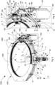
- a movement group 1 arranged for moving an operating group 100 around a load 2 ( Figure 1 ), for example a load 2 arranged on a support like, for example, a pallet, or a support provided with roller or chain movements is illustrated.
- the movement group 1 is suitable for being installed in a wrapping apparatus 1000 which is designed to wrap a film around the load 2 with a set number of wrapping coils during a wrapping cycle.
- the film is made of an elastic material and/or plastics, for example can be an extendible film having elasticity that is such as to be able to be applied to and shaped around the load and, at the same time, such as to be able to keep together the latter stably.
- the film can be, in particular, a microperforated film and/or a biodegradable film and/or a heat-sensitive film.
- the wrapping apparatus 1000 is provided with the operating group 100 with which the movement group 1 according to the invention is associable.
- the operating group 100 can comprise, in particular, a support and unwinding group 101 for supporting and unwinding a reel 102 of film by a rotation of the support and unwinding group 101 around the load 2 so as to apply a certain number of wrapping coils to the load 2.
- the film unwound from the reel 102 can be stretched before being wrapped around the load 2 and diverted to the load 2 by one or more pre-stretching and diverting rollers, of known type, of the support and unwinding group 101.
- the operating group 100 moved in use by the movement group 1 follows a trajectory around a vertical wrapping axis Y in particular for wrapping the load 2 with the film along a movement direction, for example an anticlockwise rotation direction.
- the movement group 1 is configured to move the operating group 100 so that the latter performs, for example, a rotation along a substantially circular trajectory around the vertical wrapping axis Y.
- vertical or “substantially vertical” means an axis that is substantially vertical to the gravity-accelerating vector.
- the wrapping apparatus 1000 comprises a fixed frame, which is not shown in the Figures, restable for example on a floor, and a main frame 1001 connected to the fixed frame and movably axially so that the main frame 1001 can be moved by alternating motion along a descent direction or an ascent direction, these directions being substantially parallel to a central axis C of the load 2 substantially coinciding with the, or parallel to the vertical wrapping axis Y.
- the central axis C of the load 2 is an axis passing through the centre of gravity of the load 2.
- the main frame 1001 comprises a protection casing 1002, one part of which has been removed in the Figures to be able to enable components of the movement group 1 (or of the wrapping apparatus 1000) to be shown.
- the rotation of the operating group 100 is associated with a vertical movement of the operating group 100, i.e. along a direction substantially parallel to the vertical wrapping axis Y.
- the operating group 100 can be connected to the main frame 1001 and moved together with the latter along a substantially vertical direction.
- the movement group 1 comprises an annular support frame 3 arranged for supporting the operating group 100 during the movement of the latter around the vertical wrapping axis Y.
- the annular support frame 3 is configured to slidingly support the operating group 100.
- the operating group 100 is configured to be slidable on the annular support frame 3 so as to follow a trajectory around the vertical wrapping axis Y for wrapping the load 2 with the film.
- the wrapping apparatus 1000 comprises a work zone L arranged inside the annular support frame 3 in which the load 2 is locatable to be subjected to processing by the operating group 100.
- the annular support frame 3 is arranged inside the fixed frame.
- the annular support frame 3 is rotatably stationary, i.e. does not rotate around the vertical wrapping axis Y.
- the movement group 1 comprises a single annular support frame 3 that is rotatably stationary.
- the annular support frame 3 is, in particular, connected to the fixed frame and/or to the main frame 1001 so as so as to be able to be movable vertically so that the operating group 100 can apply a set number of wrapping coils of the film to a height of the load 2 whilst it is slided around the vertical wrapping axis Y on the annular support frame 3.
- annular support frame 3 is relatable axially with respect to the fixed frame.
- the annular support frame 3 can be connected stiffly to the main frame 1001 and be moved together with the latter vertically along the ascent or descent direction with respect to the load 2.
- the annular support frame 3 can be slidingly connected to the fixed frame.
- the annular support frame 3 can comprise at least one annular tubular element 4 on which the operating group 100 is couplable.
- the annular tubular element 4 can have, in particular, a substantially circular cross section.
- the annular support frame 3 is provided with two annular tubular elements 4 arranged on one another, in particular reciprocally parallel and spaced vertically.
- a plurality of support elements 5 for supporting the movement group 1 is connected to the annular tubular element 4 or to the annular tubular elements 4 (when a plurality of annular tubular elements 4 is provided), each support element 5 being arranged for supporting a plurality of electric tracks 1003 of the wrapping apparatus 1000.
- Each electric track 1003 has an annular conformation and is arranged inside the annular support frame 3.
- the support elements 5 are distributed peripherally and inside the annular support frame 3.
- the support elements 5 can be mounted equidistant to the annular tubular element 4 or to the annular tubes 4.
- the electrical tracks 1003 thus run near an inner perimeter of the annular support frame 3 and are connected to the plurality of support elements 5 to be supported thereby.
- the support elements 5 further have the object of stiffly connecting together the annular tubular elements 4.
- the plurality of support elements 5 can be connected to the main frame 1001, in particular to the protection casing 1002.
- an upper portion of each support element 5 can be connected, with connecting means of known type, to the protection casing 1002.
- Each support element 5 can comprise, in particular, a bracket 6.
- the annular support frame 3 acts as a rail for the operating group 100.
- the operating group 100 comprises at least one carriage 103 provided with a plurality of idling rollers 104 arranged for sliding on the annular support frame 3, in particular on the tubular element/s 4 during rotation of the operating group 100 when moved by the movement group 1.
- the carriage 103 comprises at least one support plate 105 shaped substantially as a C and arranged for grasping the tubular element/s 4.
- the plurality of idling rollers 104 is mounted to the at least one support plate 105.
- the movement group 1 further comprises a flexible dragging member 7 directly connected to the, and arranged for dragging the, operating group 100 around the load 2.
- the flexible dragging member 7 can be chosen from a group comprising: a flat belt, a V-belt, a belt provided with grooves, a toothed belt, an articulated chain of roller type, an articulated chain of the Half link type.
- the flexible dragging member 7 can be made so as to be elastic, i.e. after being subjected to an external force, like a force acting along a direction substantially perpendicular to the vertical wrapping axis, reacquires the initial shape when this external force ceases.
- the flexible dragging member 7 is mounted closed in a loop, in particular outside the annular support frame 3.
- the movement group 1 can further comprise a connecting element 8 arranged for connecting, in particular stiffly, the operating group 100 to the flexible dragging member 7.
- the connecting element 8 that connects directly the flexible dragging member 7 to the operating group 100 ensures that, in use, the flexible dragging member 7 and the operating group 100 move integrally around the vertical wrapping axis Y.
- the flexible dragging member 7 is fixed to the operating group 100 so that they move integrally around the vertical wrapping axis Y.
- the connecting element 8 can comprise a pair of clamps 9 between which the flexible dragging member 7 is clamped.
- a portion of inner surface 17 of the flexible dragging member 7 and an outer surface portion 20 can be clamped between the clamps 9, the portion of inner surface 17 and the outer surface portion 20 being mutually opposite.
- the portion of inner surface 17 faces, in particular, the work zone L.
- the portion of inner surface 17 is arranged at a lesser distance from the vertical wrapping axis Y with respect to the outer surface portion 20.
- the connecting element 8 can be mounted to a frame element 106 of the operating group 100 to which the operating components of the operating group 100 can be mounted, like, for example, the reel 102.
- the frame element 106 can be further connected to the at least one support plate 105.
- the electrical tracks 1003 of the wrapping apparatus 1000 are configured to be contacted by a brush element 107 of the operating group 100 connected to components of the operating group 100 that have to be supplied electrically.
- the brush element 107 establishes a sliding contact on the electrical tracks 1003 to transmit an electric signal or electric energy from the electrical tracks 1003 to the components of the operating group 100 that need an electric supply.
- the movement group 1 further comprises motor means 10 configured to advance the operating group 100 along the trajectory around the vertical wrapping axis Y.
- the motor means 10 can comprise a motor, like, for example an electric motor.
- the motor means 10 is rotationally stationary, i.e. does not rotate around the vertical wrapping axis Y.
- the motor means 100 can be connected to the main frame 1001, in particular to the protection casing 1002.
- the motor means 10 can be connected to the protection casing 1002 by connecting means of known type, comprising, for example, a plate element 1004.
- the movement group 1 further comprises a flexible driving member 11 connected to the, and movable by the, motor means 10.
- the flexible driving member 11 can be chosen from a group comprising: a flat belt, a V-belt, a belt provided with grooves, a toothed belt, an articulated chain of roller type, an articulated chain of the Half link type.
- the flexible driving member 11 can be made so as to be elastic.
- the flexible driving member 11 is mounted closed in a loop, in particular outside the annular support frame 3.
- the flexible dragging member 7 and the flexible driving member 11 are mounted so as to be separated and spaced mutually apart from one another.
- the flexible dragging member 7 and the flexible driving member 11 are arranged, in particular, one above the other mutually spaced apart from one another vertically, i.e. in a vertical direction D substantially parallel to the vertical wrapping axis Y.
- the flexible dragging member 7 is mounted below the flexible driving member 11 with respect to the vertical direction D, but in one embodiment that is not shown, the flexible dragging member 7 can be above the flexible driving member 11 with respect to the vertical direction D.
- the movement group 1 further comprises motion transmitting means 12 arranged for transmitting the motion from the flexible driving member 11 to the flexible dragging member 7.
- the flexible dragging member 7 and the flexible driving member 11 are mounted spatially separate and the flexible driving member 11 does not drag the flexible dragging member 7 by friction. In this manner, possible wear to the flexible dragging member 7 and the flexible driving member 11 through mutual rubbing is avoided.
- the motion transmitting means 12 can comprise a first portion arranged for coupling with the flexible dragging member 7 and a second portion arranged for coupling with the flexible driving member 11.
- the first portion and the second portion are mounted separately and spaced mutually apart from one another so that the flexible dragging member 7 and the flexible driving member 11 are in turn mounted separated and spaced mutually apart from one another.
- the operating group 100 that, as said, is connected stiffly to the flexible dragging member 7, is dragged around the vertical wrapping axis Y when the flexible dragging member 7 is moved around the vertical wrapping axis Y by the flexible driving member 11 by means of the motion transmitting means 12.
- the motion transmitting means 12 can comprise a plurality of motion transmitting devices 13 distributed peripherally and outside the annular support frame 3.
- the motion transmitting devices 13 can be (equally) spaced apart angularly.
- the flexible dragging member 7 and the flexible driving member 11 are mounted closed in a loop on at least one part of the motion transmitting devices 13.
- the flexible dragging member 7 and the flexible driving member 11 are mounted stretched on at least one part of the motion transmitting devices 13.
- the flexible dragging member 7 and the flexible driving member 11 are mounted to the motion transmitting means 12, in particular to at least one part of the motion transmitting devices 13, such that they are arranged on top of one another spaced mutually apart from one another vertically, i.e. in the vertical direction D substantially parallel to the vertical wrapping axis Y.
- Each motion transmitting device 13 can comprise a shaft element 14 extending along an axis of vertical extent V substantially parallel to the vertical wrapping axis Y.
- the shaft element 14 can be shaped substantially as a pin.
- Each motion transmitting device 13 can further comprise a first revolving transmission element 15 that is rotatable around a first vertical rotation axis R1 and provided with a first lateral revolving surface 16 on which it is configured to engage a portion of inner surface 17 of the flexible dragging member 7.
- portions of inner surface 17 slide progressively on the first lateral revolving surfaces 16 of the motion transmitting devices 13.
- the first lateral revolving surfaces 16 of the motion transmitting devices 13 on which inner surface portions 17 of the flexible dragging member 7 engage define the first portion of the motion transmitting means 12.
- Each first revolving transmission element 15 can comprise a pulley that is each chosen from a group comprising: a flat pulley, a V pulley, a pulley provided with grooves, a toothed pulley, a conical pulley.
- the first revolving transmission elements 15 can have a different configuration from one another.
- each configuration can comprise pulleys of different type.
- Each motion transmitting device 13 can further comprise a second revolving transmission element 18 that is rotatable around a second vertical rotation axis R2 and is provided with a second lateral revolving surface 19 on which it is configured to engage a portion of inner surface 21 of the flexible driving member 11.
- the second lateral revolving surfaces 19 of the motion transmitting devices 13 define the second portion of the motion transmitting means 12.
- Each second revolving transmission element 18 can comprise a pulley that is each chosen from a group comprising: a flat pulley, a V pulley, a pulley provided with grooves, a toothed pulley, a conical pulley.
- the second revolving transmission elements 18 can have a different configuration from one another.
- each configuration can comprise pulleys of different type.
- the first revolving transmission element 15 and the second revolving transmission element 18 are, in particular, splined on the shaft element 14 spaced vertically apart in the vertical direction D, i.e. a direction substantially parallel to the vertical wrapping axis Y.
- first revolving transmission element 15 and the second revolving transmission element 18 are joined with the shaft element 14 by interlocking.
- the axis of vertical extent V of the shaft element 14 and/or the first rotation axis R1 of the first revolving transmission element 15 and/or the second rotation axis R2 of the second revolving transmission element 18 can be substantially coincident.
- the arrangement of the axes of the first revolving transmission elements 15 (first axes of rotation R1), and/or of the second revolving transmission elements 18 (second axes of rotation R2) of different transmitting devices 13, can be different in the motion transmitting devices 13.
- the plurality of motion transmitting devices 13 of the motion transmitting means 12 can be connected to the main frame 1001, in particular to the protection casing 1002.
- an upper portion of each shaft element 14 can be connected, with connecting means of known type, to the protection casing 1002.
- the first revolving transmission element 15 and the second revolving transmission element 18 can have different dimensions.
- the corresponding pulleys can have diameters that are different from one another and/or are different in the various motion transmitting devices 13.
- the movement group 1 further comprises a driving rolling element 22 connected, in particular mounted, to the motor means 10 to be rotated by the latter around a rotation axis T of the driving rolling element 22.
- the driving rolling element 22 can comprise an outer rolling surface on which the flexible driving member 11 is configured to engage, in particular a portion of inner surface 21 of the flexible driving member 11.
- the driving rolling element 22 can comprise a pulley chosen from a group comprising: a flat pulley, a V pulley, a pulley provided with grooves, a toothed pulley, a conical pulley.
- the driving rolling element 22 and the motor means 10 are mounted outside the annular support frame 3 to avoid occupying the work zone L arranged inside the annular support frame 3 and in which the load 2 is locatable.
- the movement group 1 can further comprise at least one return and diverting rolling element 23 that is freely rotatable around a rotation axis A and comprises a rolling surface 24 configured to engage a portion of outer surface 25 of the flexible driving member 11.
- the outer surface 25 of the flexible driving member 11 and the inner surface 21 of the flexible driving member 11 are mutually opposite.
- the portion of inner surface 21 faces the work zone L.
- the movement group 1 can comprise a plurality of return and diverting rolling elements 23 freely rotatable around a respective rotation axis A and each comprising a respective rolling surface 24 configured to engage a portion of outer surface 25 of the flexible driving member 11.
- Each rotation axis A can be arranged at a distance from the wrapping vertical axis Y greater than each axis of vertical extent V of the shaft elements 14.
- the at least one or each return and diverting rolling element 23 can each comprise a pulley that is each chosen from a group comprising: a flat pulley, a V pulley, a pulley provided with grooves, a toothed pulley, a conical pulley.
- the at least one or each return and diverting rolling element 23 can comprise, in particular, a first return and diverting rolling element 26 and a second return and diverting rolling element 27 so positioned with respect to the driving rolling element 22 that the flexible driving member 11 advances, near the driving rolling element 22, with a path having a substantially omega ⁇ plan shape.
- the movement group 1 can further comprise at least one rolling return and spacing element 28 that is freely rotatable around a rotation axis B and comprises a rolling spacing surface 29 configured to engage a portion of inner surface 17 of the flexible dragging member 7.
- the movement group 1 can comprise a plurality of return and spacing elements 28 each of which is freely rotatable around a respective rotation axis B and comprises a respective rolling spacing surface 29 configured to engage a portion of inner surface 17 of the flexible dragging member 7.
- each rolling return and spacing element 28 can be arranged at a distance from the wrapping vertical axis Y greater than each axis of vertical extent V of the shaft elements 14.
- the at least one or each rolling return and spacing element 28 is connected, in particular mounted, to the operating group 100.
- the at least one or each rolling return and spacing element 28 is mounted to the frame element 106.
- the at least one or each rolling return and spacing element 28 enables a portion of the flexible dragging member 7 to be spaced apart (spaced apart portion 30) from the vertical wrapping axis Y, near the zones in which the return and spacing elements 28 are located, i.e. near the operating group 100.
- the spaced apart portion 30 is spaced apart from the remaining portions of flexible dragging member 7. Owing to the spaced apart portion 30, it is avoided that components of the operating group 100 of large dimensions can hit the motion transmitting devices 13 when the operating group 100 is dragged by the flexible dragging member 7.
- the flexible dragging member 7 can therefore not engage one or more of the first lateral revolving surfaces 16 when the spaced apart portion 30 reaches these first lateral revolving surfaces 16.
- the flexible dragging member 7 can be mounted closed in a loop on a part of the dragging devices 13, i.e. on only one part of the first lateral revolving surfaces 16.
- the first lateral revolving surfaces 16 which the flexible dragging member 7 engages vary during the movement of the operating group 100, i.e. on the basis of the positioning of the spaced apart portion 30 (and thus of the operating group 100).
- the flexible driving member 11 can be mounted closed in a loop on all the dragging devices 13, i.e. on all the second lateral revolving surfaces 19.
- Each rolling return and spacing element 28 can comprise a pulley that is each chosen from a group comprising: a flat pulley, a V pulley, a pulley provided with grooves, a toothed pulley, a conical pulley.
- the movement group 1 can comprise a first rolling return and spacing element 31 and a second rolling return and spacing element 32 mounted near and respectively upstream and downstream of the connecting element 8 with respect to the movement direction of the operating group 100 to enable the operating group 100 to be spaced apart from the motion transmitting means 12.
- the motor means 10 is driven, in particular rotated. This rotates the driving rolling element 22 around the rotation axis T thereof. Owing to the connection between the driving rolling element 22 and the flexible driving member 11, which flexible conducting member 11 is mounted with a portion of inner surface 21 thereof in contact engagement with the outer rolling surface of the driving rolling element 22, the flexible driving member 11 is moved.
- the flexible driving member 11 can be moved by direct contact with the motor means 10.
- the flexible driving member 11 rotates around the respective second vertical rotation axes R2 the second transmission rolling elements 18 which the flexible driving member 11 engages.
- each second rolling transmission element 18 and a respective first rolling transmission element 15 are splined on a respective shaft element 14
- the rotation of the second transmission rolling elements 18 around the second vertical rotation axes R2 involves a resulting rotation of the first rolling transmission elements 15 around the respective first vertical rotation axes R1.
- the first rolling transmission elements 15 transmit motion to the flexible dragging member 7 which the flexible dragging member 7 engages.
- the flexible dragging member 7 accordingly drags, in particular rotationally, the operating group 100 to which it is stiffly connected. In this manner, the movement group 1 moves the operating group 100 around the vertical wrapping axis Y.
Landscapes
- Engineering & Computer Science (AREA)
- Mechanical Engineering (AREA)
- Transmission Devices (AREA)
Applications Claiming Priority (1)
| Application Number | Priority Date | Filing Date | Title |
|---|---|---|---|
| IT102023000015570A IT202300015570A1 (it) | 2023-07-25 | 2023-07-25 | Gruppo di movimentazione per movimentare un gruppo operativo di un apparato avvolgitore |
Publications (1)
| Publication Number | Publication Date |
|---|---|
| EP4512727A1 true EP4512727A1 (de) | 2025-02-26 |
Family
ID=88291310
Family Applications (1)
| Application Number | Title | Priority Date | Filing Date |
|---|---|---|---|
| EP24190531.4A Pending EP4512727A1 (de) | 2023-07-25 | 2024-07-24 | Bewegungsgruppe zum bewegen einer arbeitsgruppe eines einwickelgerätes |
Country Status (2)
| Country | Link |
|---|---|
| EP (1) | EP4512727A1 (de) |
| IT (1) | IT202300015570A1 (de) |
Citations (3)
| Publication number | Priority date | Publication date | Assignee | Title |
|---|---|---|---|---|
| EP1319596A2 (de) | 2001-12-13 | 2003-06-18 | OFFICINA MECCANICA SESTESE S.p.A. | Mechanisch geregelte Abgabevorrichtung für Umhüllungsmaschinen und Umhüllungsmaschine mit einer solchen Vorrichtung |
| EP2046647B1 (de) * | 2006-07-07 | 2012-03-14 | AETNA GROUP S.p.A. | Einwickelmaschine und einwickelverfahren |
| EP2468635A1 (de) | 2010-12-27 | 2012-06-27 | Pomatec di Podeschi Mauro | Umwicklungsmaschine |
-
2023
- 2023-07-25 IT IT102023000015570A patent/IT202300015570A1/it unknown
-
2024
- 2024-07-24 EP EP24190531.4A patent/EP4512727A1/de active Pending
Patent Citations (4)
| Publication number | Priority date | Publication date | Assignee | Title |
|---|---|---|---|---|
| EP1319596A2 (de) | 2001-12-13 | 2003-06-18 | OFFICINA MECCANICA SESTESE S.p.A. | Mechanisch geregelte Abgabevorrichtung für Umhüllungsmaschinen und Umhüllungsmaschine mit einer solchen Vorrichtung |
| EP1319596B1 (de) | 2001-12-13 | 2006-02-01 | OFFICINA MECCANICA SESTESE S.p.A. | Mechanisch geregelte Abgabevorrichtung für Umhüllungsmaschinen und Umhüllungsmaschine mit einer solchen Vorrichtung |
| EP2046647B1 (de) * | 2006-07-07 | 2012-03-14 | AETNA GROUP S.p.A. | Einwickelmaschine und einwickelverfahren |
| EP2468635A1 (de) | 2010-12-27 | 2012-06-27 | Pomatec di Podeschi Mauro | Umwicklungsmaschine |
Also Published As
| Publication number | Publication date |
|---|---|
| IT202300015570A1 (it) | 2025-01-25 |
Similar Documents
| Publication | Publication Date | Title |
|---|---|---|
| EP3109173B1 (de) | Folienabwicklungsvorrichtung für eine verpackungsmaschine und verpackungsmaschine | |
| EP2403782B1 (de) | Vorrichtung und verfahren zur übertragung von waren zwischen fördereinrichtungen | |
| US7823718B2 (en) | Dynamic conveyance device | |
| JP2022541038A (ja) | チェーン移送システム | |
| US20160325860A1 (en) | Apparatus, system and method for adjustable wrapping | |
| EP4512727A1 (de) | Bewegungsgruppe zum bewegen einer arbeitsgruppe eines einwickelgerätes | |
| CN112830001B (zh) | 一种具有配重功能的筒纱暂存系统 | |
| EP2204323B1 (de) | Umwicklungsmaschine | |
| WO2025074313A1 (en) | Movement group for moving an operating group of a wrapping apparatus | |
| CN219057442U (zh) | 通用化滚筒式输送装置 | |
| US4671760A (en) | Apparatus for stretching a plastic raw material | |
| CN211711833U (zh) | 一种传送线步进进给机构 | |
| US4561536A (en) | Rotary conveyor apparatus | |
| CN113172377A (zh) | 一种底座焊接机械结构 | |
| JPH0671720B2 (ja) | ウォータジェット加工機 | |
| US2727401A (en) | Card driving mechanisms | |
| EP0191556A1 (de) | Sprühgerät | |
| CN118125037B (zh) | 一种皮带机支撑装置 | |
| US795343A (en) | Pie-making machine. | |
| SU1085910A1 (ru) | Подъемное устройство | |
| SU1712497A1 (ru) | Устройство дл центрировани ленточного материала | |
| US4051701A (en) | Leather softening machines | |
| SU1407804A2 (ru) | Устройство дл обработки дерев нных изделий | |
| CN117401347A (zh) | 一种钢结构用的材料运输设备 | |
| US3206010A (en) | Counterweighted take-up system |
Legal Events
| Date | Code | Title | Description |
|---|---|---|---|
| PUAI | Public reference made under article 153(3) epc to a published international application that has entered the european phase |
Free format text: ORIGINAL CODE: 0009012 |
|
| STAA | Information on the status of an ep patent application or granted ep patent |
Free format text: STATUS: THE APPLICATION HAS BEEN PUBLISHED |
|
| AK | Designated contracting states |
Kind code of ref document: A1 Designated state(s): AL AT BE BG CH CY CZ DE DK EE ES FI FR GB GR HR HU IE IS IT LI LT LU LV MC ME MK MT NL NO PL PT RO RS SE SI SK SM TR |
|
| STAA | Information on the status of an ep patent application or granted ep patent |
Free format text: STATUS: REQUEST FOR EXAMINATION WAS MADE |
|
| 17P | Request for examination filed |
Effective date: 20250820 |