EP4512959A1 - Engin de construction routière, en particulier finisseur ou chargeur, et procédé de rééquipement d'un tel engin de construction routière - Google Patents
Engin de construction routière, en particulier finisseur ou chargeur, et procédé de rééquipement d'un tel engin de construction routière Download PDFInfo
- Publication number
- EP4512959A1 EP4512959A1 EP24191198.1A EP24191198A EP4512959A1 EP 4512959 A1 EP4512959 A1 EP 4512959A1 EP 24191198 A EP24191198 A EP 24191198A EP 4512959 A1 EP4512959 A1 EP 4512959A1
- Authority
- EP
- European Patent Office
- Prior art keywords
- road construction
- construction machine
- base part
- replacement
- pivoting
- Prior art date
- Legal status (The legal status is an assumption and is not a legal conclusion. Google has not performed a legal analysis and makes no representation as to the accuracy of the status listed.)
- Pending
Links
Images




Classifications
-
- E—FIXED CONSTRUCTIONS
- E01—CONSTRUCTION OF ROADS, RAILWAYS, OR BRIDGES
- E01C—CONSTRUCTION OF, OR SURFACES FOR, ROADS, SPORTS GROUNDS, OR THE LIKE; MACHINES OR AUXILIARY TOOLS FOR CONSTRUCTION OR REPAIR
- E01C19/00—Machines, tools or auxiliary devices for preparing or distributing paving materials, for working the placed materials, or for forming, consolidating, or finishing the paving
- E01C19/48—Machines, tools or auxiliary devices for preparing or distributing paving materials, for working the placed materials, or for forming, consolidating, or finishing the paving for laying-down the materials and consolidating them, or finishing the surface, e.g. slip forms therefor, forming kerbs or gutters in a continuous operation in situ
-
- E—FIXED CONSTRUCTIONS
- E01—CONSTRUCTION OF ROADS, RAILWAYS, OR BRIDGES
- E01C—CONSTRUCTION OF, OR SURFACES FOR, ROADS, SPORTS GROUNDS, OR THE LIKE; MACHINES OR AUXILIARY TOOLS FOR CONSTRUCTION OR REPAIR
- E01C2301/00—Machine characteristics, parts or accessories not otherwise provided for
- E01C2301/02—Feeding devices for pavers
Definitions
- the invention relates to a road construction machine, in particular a road paver or feeder, and to a method for converting such a road construction machine.
- Generic road construction machines are in particular so-called road pavers or feeders. These machines are usually used in road or path construction, as well as in the creation of squares. Their main function is to pick up a paving material, for example asphalt or concrete, from a delivery vehicle, for example a truck, and to spread it on the ground in a layer thickness and to leave a uniform, ideally pre-compacted, layer of the paving material or to be used to support this.
- Road pavers and feeders usually have a machine frame, a driver's cab and a drive motor, which is for example an internal combustion engine, usually a diesel internal combustion engine. They are self-propelled machines that comprise a chassis with at least one left driving device and one right driving device.
- Road pavers and feeders with both tracked drives and wheels are known and are equally covered by the present invention.
- Such a road paver is for example in the DE 10 2018 000 576 A1
- a feeder and a road paver are in the DE 10 2016 006 187 A1 disclosed.
- the road finisher comprises a screed for smoothing and compacting the paving material laid out on the ground surface.
- the feeder can be constructed in a practically identical manner, but instead of the screed it has a transfer device with which the paving material stored in it can be transferred to a road finisher following the feeder.
- the feeder is thus a type of buffer vehicle to enable a continuous supply of the road finisher with paving material when delivery vehicles change.
- these road construction machines typically have a material bunker arranged at the front of the road construction machine in the direction of paving.
- the material bunker thus refers to a receiving space in which the road construction machine can receive paving material, usually from a truck, and store it for the paving process.
- the material bunker has a bunker floor, bunker side walls and a bunker rear wall.
- the material bunker can comprise a left and a right pivoting part. These pivoting parts are sometimes also referred to as bunker halves. These pivoting parts of the material bunker can be pivoted or swiveled up from a pivoted filling position to an emptying position in order to move paving material onto a longitudinal conveyor device positioned below and at least partially between the two pivoting parts.
- the bunker halves are each designed to be pivoted or tilted upwards about a pivot axis that runs essentially in the paving direction.
- the bunker halves pour the paving material stored in them onto the longitudinal conveyor device, which is usually arranged between the bunker halves, which then transports the paving material backwards in the direction of the paving screed of the road paver or in the direction of the transfer device on the feeder, seen in the paving direction.
- the longitudinal conveyor device is normally arranged between the pivoting parts and extends backwards in the paving direction.
- the bunker halves can therefore be adjusted between a filling position, in which the material bunker's capacity is at its maximum, and an emptying position, in which the material bunker's capacity is reduced.
- a material bunker is, for example, in the previously mentioned DE 10 2018 000 576 A1 revealed. 1
- the left and right swivel parts each comprise different wall elements.
- the left and right swivel parts each have a bunker floor element, a protruding bunker side wall element and a protruding bunker rear wall element.
- the bunker floor forms a floor area of the material bunker. Part of this can be formed by one or more of the bunker floor elements of the swivel parts.
- the bunker side wall element delimits the receiving space of the material bunker transversely to the longitudinal axis of the road construction machine on the right or left side.
- the bunker rear wall is located at the end of the material bunker when viewed against the installation direction of the road construction machine and delimits it in the direction opposite to the installation direction or opposite a front loading edge of the material bunker. This is formed, among other things, by the bunker rear wall elements of the swivel parts.
- other wall elements in particular wall elements that are stationary relative to the machine frame of the road construction machine, can be included in the material bunker, such as, in particular, a rear wall and/or one or more floor wall elements.
- the material bunker In the installation direction towards the front, the material bunker is often designed to be lowered relative to the side wall elements and/or rear wall elements that rise up in the vertical direction and is limited by a loading edge. In the area of the loading edge Comparatively small, particularly flexible retaining elements that protrude slightly from the bunker floor in the vertical direction may be present in order to prevent installation material stored in the material bunker from falling out forwards in the installation direction.
- the paving material is delivered by trucks, for example, and poured directly into the material hopper of the road construction machine.
- the swivel parts are swiveled away for this purpose or are in their filling position. It can be provided that the road construction machine pushes the truck in front of it in front of it by causing a controlled collision during the ongoing paving process, and the paving material is filled into the material hopper.
- the paving material is transported from the material hopper of the road construction machine via the longitudinal conveyor to the rear of the road construction machine, where it is picked up by a transfer device in the case of a feeder and transferred to a subsequent road paver, or in the case of a road paver, it is distributed across the paving width, for example by means of a suitable transverse distribution device, and is smoothed and compacted by the paving screed that usually floats on the paving material.
- the road paver can also be loaded directly from a transport vehicle, so that the use of a road paver alone is optional.
- the swivel parts can be swiveled up into the emptying position separately or simultaneously when the material bunker has already been partially emptied. This creates a kind of funnel through the two swivel parts and the paving material in the side edge area of the material bunker can also slide onto the longitudinal conveyor system.
- This variant is referred to below as the "swivel variant”.
- the paving material in the material hopper slides towards the middle of the material hopper. This can cause paving material to fall out of the material hopper over the front loading edge or to accumulate on a front plate located in front of the longitudinal conveyor in the direction of installation, which also forms part of the floor area of the material hopper. Both processes can cause additional costs, either due to the resulting loss of material or due to the increased personnel deployment required during ongoing paving operations.
- a front flap instead of the front panel, which, in contrast to the front panel, no longer is not stationary relative to the machine frame, but can be swiveled up around a swivel axis that is located inside the loading edge and runs transversely to the working direction.
- a suitable actuator for example a hydraulic cylinder, can be provided, via which the adjustment movement of the front flap is driven.
- the swivel parts in an overlap area with the front flap with swiveling wing parts that are pivotably mounted on the respective swivel part, in particular a bottom wall element of the respective swivel part.
- the interaction of the front flap, the wing parts and the swivel parts makes it possible, on the one hand, to scrape the paving material located on the front flap in the direction of the longitudinal conveyor device when the swivel parts are swiveled up.
- These wing parts are therefore also referred to as scraper plates.
- the entire area of the front loading edge can be set up like a funnel, so that the falling out of the paving material from the material bunker over the front loading edge can be prevented.
- Such an arrangement is used, for example, in the DE 20 2011 108 347 U1 This variant is also referred to below as the "scratch variant".
- the object of the present invention to provide a possibility to improve the convertibility of a road construction machine, in particular a road paver or feeder.
- a generic road construction machine for laying paving material in a paving direction comprises a machine frame, a driver's station, a drive motor, a chassis with at least one left-hand driving device and one right-hand driving device, a material bunker arranged on the road construction machine in the paving direction for receiving paving material.
- the machine frame refers to the essential supporting structure of the road construction machine.
- the driver's station refers to an operator's workstation from which the road construction machine can be operated during paving operation. This can be arranged on the machine frame or can be adjustably mounted on it.
- the drive motor of the road construction machine refers to a primary drive unit, via which at least a significant part of the drive energy required for the working and driving operation of the road construction machine is generated.
- This can be, for example, an internal combustion engine, in particular a diesel internal combustion engine, a hybrid drive unit or similar.
- the chassis can comprise one or more crawler tracks and/or wheels.
- the terms “left” and “right” refer to the sides viewed in the direction of paving or forward direction of the road construction machine.
- the road paver usually comprises a basic machine comprising the above-mentioned components, which is also referred to as a tractor.
- a paving screed can be mounted on this basic machine in such a way that it is pulled by the tractor over the paving material distributed on the paving surface during paving operation, smoothing and compacting the paving material.
- the road construction machine has a material bunker which is intended for the temporary storage of the paving material.
- the material bunker comprises a bottom wall, a right and a left side wall and a rear wall which, as seen from the front of the road construction machine, delimits the material bunker to the rear.
- These walls as a whole define a receiving space in which paving material is received by the road construction machine and stored at least temporarily.
- the individual walls can consist of several interacting Wall elements can be formed, in particular by several wall elements that can be adjusted relative to one another.
- the material bunker comprises at least two pivoting parts, which usually form a large part of the wall elements of the material bunker.
- stationary wall elements can also be present.
- the material bunker comprises a left pivoting part or a left bunker half and a right pivoting part or a right bunker half.
- the two pivoting parts can be constructed essentially mirror-symmetrically to one another.
- the left and right pivoting parts can each have a rear wall element, a bottom wall element forming a floor surface of the material bunker, a side wall element rising up from the bottom wall element and, towards the front, a front loading edge running transversely to a machine longitudinal direction.
- the road construction machine further comprises a longitudinal conveyor device extending along the longitudinal axis of the machine, which is designed to transport paving material from the material hopper against a paving direction, for example in the case of a road finisher in the direction of a paving screed arranged at the rear of the road finisher and in the case of a feeder in the direction of a transfer device arranged at the rear of the feeder, for example a transfer conveyor belt.
- the right and left pivoting parts can each have an inner edge facing the longitudinal conveyor device, over which the paving material falls onto the longitudinal conveyor device.
- the longitudinal conveyor device can be arranged below the two pivoting parts in the vertical direction.
- the two pivoting parts can be spaced apart from one another with their inner edges in the horizontal plane transverse to the paving direction, so that a shaft-like free space is obtained through which the paving material can fall from the material hopper onto the longitudinal conveyor device.
- the swivel parts can each be adjusted between a swiveled-down filling position and a swiveled-up emptying position in order to move paving material onto or in the direction of the longitudinal conveyor device. They can be adjusted independently of one another.
- One or more actuators such as hydraulic cylinders, can be provided to drive the adjustment device.
- the swivel axes of the swivel parts can run in the horizontal plane and parallel to the machine's longitudinal axis or parallel to the straight-ahead alignment of the road construction machine.
- the swivel parts can be connected via suitable joint devices, in particular to the machine frame of the road construction machine. These can be hinge joints, for example.
- the bottom wall elements of the swivel parts each have a base part, in particular directly and firmly connected to the respective side wall element and the respective rear wall element, and a replacement part, in particular directly and firmly connected to the base part via a detachable fastening device, wherein the replacement part forms part of the inner edge and part of the loading edge of the floor surface of the respective swivel part.
- a preferably rigid and firmly connected whole is thus provided, consisting of a side wall element, a rear wall element, a base part and a replacement part.
- the side wall element, the rear wall element and the base part can represent an overall module or a coherent component that cannot be removed without causing damage.
- These individual parts can be connected to one another in a materially bonded manner, for example by means of welded connections and/or at least partially formed, for example bent, from a common preform, for example a sheet of metal.
- this component When this component is used as intended, these components are thus inseparably connected to one another.
- the situation is different with the replacement part.
- This is also fixed and preferably arranged directly on the base module, in particular on the base wall element, and connected to it.
- the special feature is that the replacement element is attached to this base module via a detachable fastening device and thus acts in this arrangement as a part of the base module that is firmly connected to the base module.
- this part of the pivoting part can be easily removed and dismantled from the rest of the pivoting part and in particular from the base part by loosening the fastening device and can then be replaced, for example, by a wing element that can be pivoted relative to the base part to convert to the "scratching variant".
- the swivel parts each have a base part and a connected replacement part, wherein the replacement part forms a part of the inner edge and a part of the loading edge of the floor surface of the respective pivoting part and wherein the floor wall element is formed jointly by the base part and the replacement part.
- the replacement part is surrounded exclusively by at least a part of the loading edge, a part of the inner edge, in particular towards the longitudinal conveyor device, and an abutting edge towards the base part. In other words, in this projection plane, only these three edges form the outer edges of the replacement part.
- the replacement part is designed such that in this horizontal projection plane, at least with regard to its surface as part of the base wall surface, it essentially has the shape of a triangle, in particular a right-angled triangle.
- the floor surface of the material bunker does not have to be completely flat and level. For example, elevations can be provided at the edges that rise up to the operator's stand in order to improve visibility for an operator in certain operational situations. Elevations can also be present for reasons of installation space, for example due to the presence of additional components, such as the driving devices arranged below the material bunker.
- the base part and the replacement part are designed in such a way that the floor surface formed by the base part and the floor surface formed by the replacement part are designed, at least in the adjacent area, in such a way that they merge seamlessly into one another. This means that at least in this area the total floor surface obtained from the base part and the replacement part is flat or the floor surface made up of the base part and the replacement part is essentially designed as a flat total surface.
- the replacement part is designed in such a way that the entire floor surface formed by it is flat and lies in the horizontal projection plane, in particular when the respective pivoting part is in the filling position.
- the material hopper of the road construction machine can have a front plate, in particular one that is arranged stationary relative to the machine frame.
- the front plate can be arranged in a front area of the material hopper, in particular in the installation direction seen in the area between the longitudinal conveyor device and the front loading edge.
- the front plate can thus form part of the floor area of the material bunker in this area and, in the front area of the material bunker, bridge the distance between the loading edges of the pivoting parts and the longitudinal conveyor device transversely to the installation direction.
- the replacement part is now designed and arranged in the pivoting part in such a way that it is arranged to at least partially overlap the front plate of the material bunker in the vertical direction.
- the replacement part and/or part of the inner edge, in particular towards the longitudinal conveyor device, of the replacement part run in an overlap area with the front plate.
- the replacement part and the base part are designed in such a way that the abutting edge of the replacement part to the base part has no overlap with the front plate.
- the detachable fastening device It is essential for the specific design of the detachable fastening device that it can be released from its fastening state when used as intended in order to be able to detach the replacement part from the base part without causing any damage.
- suitable aids such as one or more tools, including motor-driven ones. It is essential that neither the replacement part nor the base part have to be damaged.
- the detachable fastening device partially comprises elements and/or devices that are formed by the base part or the replacement part itself, such as one or more form-fitting elements that are at least partially complementary to one another in the connection area between the replacement part and the base part, such as one or more contact and/or guide rails, locking rails and/or similar fitting elements.
- One or more through holes for receiving one or more fastening elements can also be included in the base part and/or the replacement part.
- the fastening device can also include additional elements that are intended in particular to interact with parts of the fastening device that are formed by the base part or the replacement part.
- one or more detachable screw connections for example screw bolts secured by nuts, which are guided through opposing through holes in the base part and the replacement part, can be present.
- the fastening device can comprise one or more detachable screw connections whose thread axes run parallel to each other and/or extend substantially parallel to the plane of the base surface.
- the fastening device is arranged completely below the parts of the overall bottom wall of the material bunker formed by the base part and the replacement part. Accordingly, it is advantageous if the fastening device is arranged at least partially on an underside of the pivoting part. This means that the fastening device is not only protected from the paving material when the road construction machine is in operation. It is also relatively easy to access from outside the road construction machine, at least when the pivoting part is in the emptying position, which can make the conversion process even easier.
- the road construction machine can have one or more adjustment actuators that are designed and arranged to drive an adjustment movement of a swivel part from the filling position to the emptying position.
- adjustment actuators can be, for example, hydraulic cylinders or similar. It is now preferably provided if the actuator or actuators are arranged, in particular exclusively, between the machine frame and the base part and/or the side wall element of the swivel part. In other words, it is preferred if none of the actuators are directly linked to the replacement part.
- the base part and the replacement part each have an edge that faces each other when the replacement part is fixed but detachably connected to the base part.
- These edges can also be referred to as abutting edges, in particular when the base part and the replacement part abut each other directly and immediately when assembled together. It is preferred if these abutting edges between the base part and the replacement part are not only complementary to each other, but also linear, in particular completely linear.
- a receiving space is provided and kept free below the front plate of a road construction machine in the "swivel variant", in which an actuator can be arranged to drive an adjustment movement of a front flap that can be adjusted between a swiveled-down loading position and a swiveled-up unloading position when converting to the "scraper variant".
- one or more connection points that are not used in the swivel variant can be pre-installed in the hydraulic system of this road construction machine, via which this actuator is connected to the hydraulic system of the road construction machine when the road construction machine is converted to the "scraper variant".
- a sensor system and/or a machine control unit of the road construction machine can already include the components required to operate the "scraper variant" even in the "swivel variant” configuration.
- the preparatory measures for the "scraping variant" in the swivel variant can go so far that it is also possible to convert the road construction machine in the field.
- a further aspect of the invention relates to a method for converting a road construction machine according to the invention, in particular a road finisher or a feeder.
- a road construction machine in particular a road finisher or a feeder.
- the method according to the invention initially comprises, in a step a), the dismantling of the replacement part from the base part.
- a step a the dismantling of the replacement part from the base part.
- at least one release of the fastening device takes place which has connected the replacement part to the base part in such a way that these two elements have formed a stationary unit.
- This step is therefore preferably carried out on a road construction machine whose material hopper is designed as a "swivel variant".
- an attachment of a The scraper plate can be pivoted from the base part via a pivot joint.
- the fastening device now comprises at least one pivot joint, so that a plate part is again connected to the base part via a fastening device, but this time it is no longer stationary, but adjustable relative to it, in particular pivotable about a pivot axis.
- the scraper plate is also preferably larger than the replacement part.
- step b it is optimal if this is done using at least some of the parts of the fastening device on the base part that were used to attach the replacement part to the base part.
- the parts of the fastening device on the base part that were used to attach the replacement part to the base part.
- a front plate that is stationary relative to the machine frame is replaced by a front flap that can be pivoted relative to the machine frame between a swiveled-down loading position and a swiveled-up unloading position.
- the entire front loading edge can be raised like a funnel when the swivel parts and the front plate are adjusted to the emptying and unloading position.
- an actuator must also be connected to the front flap.
- this actuator is already pre-installed at the factory for a road construction machine manufactured in the "swivel variant" configuration.
- this actuator can also be installed in the road construction machine as part of the conversion described above, whereby suitable connection points can then be pre-installed in the hydraulic system of the road construction machine at least at the factory for connecting the actuator to the hydraulic system of the road construction machine.
- the conversion of the road construction machine may additionally or alternatively include connecting one or more sensors to the actuator and/or to a machine control unit.
- FIG 1 shows a road construction machine 1, specifically a road finisher.
- the road construction machine 1 comprises a driver's cab 2, a machine frame 3, a drive motor 4 (in the Fig. 1 not shown in detail), for example an electric or combustion engine, and a material bunker 5 arranged at the front in installation direction a.
- the installation direction a refers to the direction in which the road construction machine 1 moves over the ground during operation.
- the road construction machine 1 extends with its longitudinal direction in a straight installation direction a.
- the road construction machine 1 comprises a chassis 6 for propulsion, for example comprising one or more crawler tracks and/or wheels as driving devices.
- the chassis 6 comprises a right and a left crawler track as driving devices.
- the road construction machine 1 is a road paver.
- This also includes a paving screed 7. This is usually pulled by the rest of the road paver floating on a material mat laid out at the rear and smoothes and compacts the laid out paving material.
- the material hopper 5 of the road paver is filled with paving material by, for example, a truck driving in front of the road paver.
- the material hopper 5 can be filled by a so-called feeder.
- Such feeders are also road construction machines 1 and also have a basic structure comparable to that of the road paver.
- the main difference between the feeder and the road paver is that instead of the paving screed 7, there is a loading conveyor belt, via which paving material stored in the feeder's material hopper can be transferred to the material hopper of the road paver, which usually drives behind the feeder during the paving process, in order to ultimately facilitate a continuous paving process of the road paver.
- a longitudinal conveyor device 8 is provided, for example in the form of a scraper floor or similar, via which paving material can be transported from the material hopper 5 to the rear of the road construction machine 1 in the paving direction a.
- the paving material reaching the rear area of the road construction machine 1 is then, in the case of a feeder, it is transferred to a subsequent road finisher using a conveyor device or, in the case of a road finisher, it is distributed across the entire paving width transversely to the paving direction a and smoothed and compacted by the paving screed 7.
- the road finisher can have a transverse distribution device, for example in the form of conveyor screws.
- the road construction machine 1 is operated from the operator's station 2.
- there is usually at least one operating device within the operator's station for example in the form of an operating panel or an operating console.
- the operator stands or sits in front of the operating device within the operator's station 2, viewed in the paving direction a.
- the material bunker 5 thus serves to receive and store the paving material on the road construction machine 1. It is desirable if the material bunker 5 provides a sufficiently large storage volume for paving material. On the other hand, it is also advantageous if the material bunker 5 is designed in such a way that the paving material stored in it can be emptied as quantitatively as possible and fed into the paving process.
- the material bunker 5 comprises pivoting parts 9l and 9r, which can be moved between a filling position, such as in the Fig. 1 shown, and an emptying position, such as in the Fig. 2 shown, are adjustable, in particular pivotable about a pivot axis running horizontally and in the installation direction a.
- the material hopper arranged on the road construction machine 1 in the installation direction a comprises a right-hand swivel part 9r and a left-hand swivel part 9l. These are between the swivelled filling position (for example according to Fig. 3 ), in which the receiving volume of the material bunker 5 is at its largest, each time around a pivot axis S running in the installation direction a into an emptying position, for example shown in Fig. 4 , can be swung open.
- the material bunker 5 comprises a rear wall 10, a base wall 11 and side walls 12. These walls are at least partially formed by the two swivel parts 9r, 9l, which for this purpose have a rear wall element 11 ⁇ , a base wall element 12' and a side wall element 13'.
- the rear wall element 11', the base wall element 12' and the side wall element 13' thus move as a whole around the respective swivel axis S when the two swivel parts 9r, 9l are swung with the swivel part 9r, 9l.
- the rear wall 11 and also the base wall 12 can additionally comprise parts that are stationary to the machine frame 3 and are accordingly not pivoted when the pivoting parts 9r, 9l are adjusted and accordingly maintain their relative position to the machine frame 3.
- the material bunker 5 is further designed to be lowered forwards in the installation direction a with respect to its upper edge and there comprises a loading edge 14.
- pivoting parts 9r, 9l each adjoin the longitudinal conveyor device 8 with an inner edge 16, over which the material to be installed falls from the respective pivoting part 9r, 9l onto the longitudinal conveyor device 8, in particular when the pivoting parts 9r, 9l are pivoted upwards individually or together about their respective pivot axis S from the filling position to their emptying position.
- Figures 3 and 4 show functionalities of the "swivel variant".
- the Figures 3 and 4 Compared to each other, they show that in this variant the swivel parts 9r and 9l are pivoted when adjusting between the filling position ( Fig. 3 ) and the emptying position ( Fig. 4 ) as a common whole uniformly pivot about the respective pivot axis S.
- This variant is comparatively cost-effective and ideally suited to many applications.
- One of the challenges for the operator of the road construction machine 1 in this variant is to ensure during operation of the road construction machine 1 when pivoting up the pivoting parts 9r, 9l that as little paving material as possible from the material bunker is pushed out of the material bunker 5 in the installation direction a over the loading edge 14, particularly in the area of a front plate 17 which is arranged stationary to the machine frame 3 and which extends in the extension of the longitudinal conveyor device 8 in the installation direction a to the loading edge 14, and is thus no longer available in the desired manner for the further paving process.
- FIG. 5 and 6 an alternative expansion stage of the material bunker 5 is the Figures 5 and 6 This differs from the "swivel variant" in that it has an increased range of functions.
- a front plate 17 which is fixed to the machine frame 3
- a front plate 17 which is horizontally and transversely to the installation direction
- the front panel 18 can be pivoted about an axis which is pivoted out in the filling position and pivoted up in the emptying position in such a way that the front loading edge 14 of the material hopper 5 is displaced upwards in the vertical direction.
- the pivoting parts 9r and 9l each comprise a scraper plate 20 which is pivotably mounted on the other pivoting part components about a pivot axis K which, in the filling position, runs horizontally and obliquely to the pivot axis S of the respective pivoting part 9r, 9l.
- the front flap 18 comprises an actuator 21, for example a hydraulic cylinder, for driving the adjustment movement of the front flap 18. Since the two scraper plates 20 overlap the front flap 18 arranged vertically below the scraper plates 20, the front flap 18 takes the two scraper plates 20 with it, so that, as a comparison of the Figures 5 and 6 As shown in the drawing, an overall structure that runs completely funnel-like in the direction of the longitudinal conveyor device 8 is also achieved in the area of the loading edge 14.
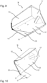
- the swivel parts 9r, 9l of the swivel variant have a base part 22 and a replacement part 23. This is particularly the case in the Figures 7, 8 and 9 illustrated in more detail.
- the descriptions given in the figures, some of which only refer to one pivoting part 9r apply equally to the left pivoting part 9l (which in this case can be designed to be mirror-symmetrical to the pivoting part 9r).
- the base part 22 and the replacement part 23 are firmly connected to one another via a fastening device 24 and in this state form a rigid whole.
- This inherently firm connection via the fastening device 24 is, however, designed to be detachable, in particular non-destructive.
- corresponding fastening openings can be provided through which detachable fastening screws or the like can be passed to connect these two parts.
- the replacement part 23 forms at least essentially and in particular exclusively a part of the base surface or base wall 12' of the respective pivoting part 9r.
- the replacement part 23 can have a part of the loading edge 14 and the inner edge 16 as well as an abutting edge 25, which is the edge of the replacement part 23 adjacent to the base part 22.
- the abutting edge 25 thus runs within the floor area of the material bunker 5.
- the replacement part can accordingly have a triangular contour in this projection plane, in particular in the form of a right-angled triangle.
- a sealing means can also be arranged between the base part 22 and the replacement part 23 in order to facilitate later release of the fastening device.
- the pivoting part 9r thus comprises the base part 22, which includes the side wall element 13', in particular completely, the rear wall element 11', in particular completely, and only a part of the bottom wall element 12'.
- the remaining part of the bottom wall element 12' is formed by the exchange part 23, which in relation to the wall elements 11', 12' and 13' preferably exclusively forms a part of the bottom wall element 12' of the pivoting part 9r.
- This entirety is pivotable as a whole and in a stationary manner also relative to the front panel 17, as shown in the Fig. 10
- the front flap 17 is stationary relative to, for example, the machine frame 3 of the road construction machine 1.
- the swivel part 9r (and also 9l), comprising the base part 22 and the replacement part 23, is pivoted into the Fig. 10
- an actuator 26 (exemplarily in the Fig. 2
- This actuator 26, for example a hydraulic cylinder, is preferably arranged between the machine frame 3 or at least a part of the road construction machine 1 that is stationary relative to the machine frame 3 and the base part 22 of the respective pivoting part 9 and is therefore not directly articulated to the exchange part 23, even if this is also possible in principle.
- the pivoting part 9r, 9l, in particular the exchangeable part 23, can be free of overlap with the front plate 17, but can also overlap it at least partially.
- the base part 22 and the replacement part 23 can be connected to one another in such a way that their base surface portions lie in a common plane. Both can be flat in the area of their base surface and can be designed in such a way that they merge seamlessly into one another.
- the division of the swivel part into the base part 22 and the replacement part 23 is therefore not actually required, since these two elements are always used as a fixed unit.
- the presence of this predetermined separation point between the base part 22 and the replacement part 23 makes it considerably easier to upgrade the road construction machine 1 from the swivel variant to the scraper variant.
- the conversion procedure provided for this is shown in the flow chart according to Fig. 13 explained in its essential steps and is also illustrated in more detail using the other figures.
- the method for converting a road construction machine 1 comprises, when the road construction machine 1 is converted from the swivel variant to the scraper variant, in a step I a dismantling of the replacement part 23 from the base part 22.
- the fastening device 24 is loosened, for example by loosening a suitable screw connection or a comparable detachable connection.
- the replacement part 23 can be selectively removed from the respective swivel part 9r, 9l, as is shown by way of example in the Fig. 8
- the remaining swivel part 9r, 9l (or the respective base part 22) can remain on the road construction machine 1.
- a scraper plate 20 that can be pivoted relative to the base part 22 is mounted on the base part 22, wherein in step III the mounting preferably takes place using at least partial use of parts of the fastening device 24 on the base part 22, by means of which the replacement part 23 was attached to the base part 22.
- the scraper plate 24 is not fixed or fixed to the base part 22, but is connected in an articulated manner, for example via a pivot joint, in particular via a pivot hinge.
- the scraper plate 20 can also differ in its contour from the replacement part 23.
- the scraper plate 20 represents a floor surface element 12' that is larger in terms of the floor surface than the replacement part 23 or has a larger floor surface and is designed to be extended further towards the longitudinal center axis or in the direction of the longitudinal conveyor device 8, in particular with its corner formed by the loading edge 14 and the abutting edge 24.
- the scraper plate 20 overlaps the area of the front plate 17 of the pivoting variant or the front plate 18 of the scraper variant and can thus pivot in relative to the base part 22 when the respective pivoting part 9r, 9l is adjusted by the pivoting movement of the pivoting part 9r, 9l itself and/or by pivoting the front flap 18 in the direction of the longitudinal conveyor device 8, thereby bringing about optimized material guidance towards the longitudinal conveyor device 8.
- the conversion process can accordingly comprise, in a step IV, replacing the front panel 17, which is stationary relative to the machine frame 3, with the front flap 18, which can be pivoted relative to the machine frame 3 between a pivoted-down loading position and a pivoted-up unloading position.
- This additional conversion step can also comprise the installation of the actuator 21 or at least the connection of the front flap 18 to the actuator 21, which can also be pre-installed.
- a receiving space 27 can be provided on the road construction machine 1, in particular below the front panel 17, in which the actuator 21 is pre-installed or can be installed later.
- the functionalities gained through the conversion described are demonstrated in particular by a comparison of the Figure 10 concerning the swivel variant with the Figures 11 and 12 concerning the scraper variant.
- the swivel part 9r swivels as a rigid whole around the swivel axis S from the filling position to the Fig. 10 This movement occurs, for example, adjacent to the front plate 17 or with a comparatively small overlap.
- the scratch variant is carried out according to the Figures 11 and 12 not only a swiveling up of the swivel part 9r, 9l, specifically from the Fig. 11 shown filling position in the direction of the Fig. 12 shown emptying position. Because the scraper plate 20 overlaps the front flap 18 (or the front plate 17), the latter additionally pivots in relative to the pivoting part 9r in the direction of the interior of the material hopper 5, scrapes over the floor surface formed by the front flap 18 (or the front plate 17) and pushes any paving material located there in the direction of the longitudinal conveyor device 8.
- the free space between the two pivoting parts 9r and 9l to the loading edge 14 is additionally tapered, so that with the help of this increased design effort, the overall risk of paving material from the material hopper 5 over the loading edge 14 when adjusting the pivoting parts 9r, 9l is reduced.
Landscapes
- Engineering & Computer Science (AREA)
- Architecture (AREA)
- Civil Engineering (AREA)
- Structural Engineering (AREA)
- Road Paving Machines (AREA)
Applications Claiming Priority (1)
| Application Number | Priority Date | Filing Date | Title |
|---|---|---|---|
| DE102023207500.8A DE102023207500A1 (de) | 2023-08-04 | 2023-08-04 | STRAßENBAUMASCHINE, INSBESONDERE STRAßENFERTIGER ODER BESCHICKER, UND VERFAHREN ZUM UMRÜSTEN EINER SOLCHEN STRAßENBAUMASCHINE |
Publications (1)
| Publication Number | Publication Date |
|---|---|
| EP4512959A1 true EP4512959A1 (fr) | 2025-02-26 |
Family
ID=92106478
Family Applications (1)
| Application Number | Title | Priority Date | Filing Date |
|---|---|---|---|
| EP24191198.1A Pending EP4512959A1 (fr) | 2023-08-04 | 2024-07-26 | Engin de construction routière, en particulier finisseur ou chargeur, et procédé de rééquipement d'un tel engin de construction routière |
Country Status (4)
| Country | Link |
|---|---|
| US (1) | US20250043521A1 (fr) |
| EP (1) | EP4512959A1 (fr) |
| CN (1) | CN223240494U (fr) |
| DE (1) | DE102023207500A1 (fr) |
Citations (5)
| Publication number | Priority date | Publication date | Assignee | Title |
|---|---|---|---|---|
| JPS59167807U (ja) * | 1983-04-23 | 1984-11-10 | 株式会社新潟鐵工所 | ホツパ装置 |
| DE202011108347U1 (de) | 2011-11-25 | 2012-01-11 | Joseph Vögele AG | Beheizter Materialbunker |
| DE102016006187A1 (de) | 2016-05-18 | 2017-11-23 | Bomag Gmbh | Straßenfertiger oder Beschicker mit Materialrückhaltevorrichtung mit Überlastschutz, Materialrückhaltevorrichtung und Verfahren zum Schutz einer Materialrückhaltevorrichtung |
| DE102018000576A1 (de) | 2017-02-03 | 2018-08-09 | Bomag Gmbh | Straßenfertiger mit Sichtausnehmung im Materialbunker |
| WO2020259812A1 (fr) * | 2019-06-25 | 2020-12-30 | Volvo Construction Equipment Ab | Finisseuse dotée d'une trémie |
-
2023
- 2023-08-04 DE DE102023207500.8A patent/DE102023207500A1/de active Pending
-
2024
- 2024-07-26 EP EP24191198.1A patent/EP4512959A1/fr active Pending
- 2024-08-02 US US18/792,677 patent/US20250043521A1/en active Pending
- 2024-08-02 CN CN202421872784.2U patent/CN223240494U/zh active Active
Patent Citations (5)
| Publication number | Priority date | Publication date | Assignee | Title |
|---|---|---|---|---|
| JPS59167807U (ja) * | 1983-04-23 | 1984-11-10 | 株式会社新潟鐵工所 | ホツパ装置 |
| DE202011108347U1 (de) | 2011-11-25 | 2012-01-11 | Joseph Vögele AG | Beheizter Materialbunker |
| DE102016006187A1 (de) | 2016-05-18 | 2017-11-23 | Bomag Gmbh | Straßenfertiger oder Beschicker mit Materialrückhaltevorrichtung mit Überlastschutz, Materialrückhaltevorrichtung und Verfahren zum Schutz einer Materialrückhaltevorrichtung |
| DE102018000576A1 (de) | 2017-02-03 | 2018-08-09 | Bomag Gmbh | Straßenfertiger mit Sichtausnehmung im Materialbunker |
| WO2020259812A1 (fr) * | 2019-06-25 | 2020-12-30 | Volvo Construction Equipment Ab | Finisseuse dotée d'une trémie |
Also Published As
| Publication number | Publication date |
|---|---|
| CN223240494U (zh) | 2025-08-19 |
| US20250043521A1 (en) | 2025-02-06 |
| DE102023207500A1 (de) | 2025-02-06 |
Similar Documents
| Publication | Publication Date | Title |
|---|---|---|
| DE102011014666B4 (de) | Gleitschalungsfertiger und Verfahren zum Neueinrichten eines Gleitschalungsfertigers | |
| EP0957204B1 (fr) | Finisseur et trémie | |
| DE102015006250B4 (de) | Anbaubohleneinheit für einen Straßenfertiger und Straßenfertiger mit einer solchen Anbaubohleneinheit | |
| EP2492396B1 (fr) | Engin routier doté d'un séparateur de matériaux | |
| DE102017009248B4 (de) | Kleinfertiger | |
| EP0779395A1 (fr) | Dispositif pour la pose de couches de revêtement | |
| DE102017104862A1 (de) | Strassenbaumaschine | |
| DE10028819A1 (de) | Verteilvorrichtung bei einem Straßenpflasterfahrzeug wie einer Asphaltiermaschine | |
| EP3284867A1 (fr) | Finisseuse pour pentes | |
| DE102018000576B4 (de) | Straßenfertiger mit Sichtausnehmung im Materialbunker | |
| DE2739452A1 (de) | Graben-auskleidungswerkzeug | |
| EP2781657B1 (fr) | Chargeur et son procédé de rééquipement | |
| DE2330548A1 (de) | Vorrichtung, die waehrend ihrer vorwaertsbewegung ein band aus einem formbaren plastischen gemisch legt | |
| EP0957205B1 (fr) | Finisseur | |
| DE3834313C2 (de) | Verfahren und Anlage zur Herstellung eines Schotterbetts für ein Eisenbahngleis | |
| EP4512959A1 (fr) | Engin de construction routière, en particulier finisseur ou chargeur, et procédé de rééquipement d'un tel engin de construction routière | |
| DE8712219U1 (de) | Gerät zum Zerkleinern von Material, insbesondere Bau- und Straßenbaumaterial | |
| EP0663478B1 (fr) | Combinaison d'une excavatrice avec un dispositif vibreur | |
| DE20103858U1 (de) | Zusatzeinrichtung für einen Fertiger | |
| DE102015016671A1 (de) | Transporteinrichtung für eine Fräseinheit, Transportfahrzeug mit einer Transporteinrichtung für eine Fräseinheit und Verfahren zum Transportieren einer Fräseinheit mit einer Transporteinrichtung | |
| DE19634013A1 (de) | Beschicker für Deckenfertiger | |
| DE3607245C2 (de) | Verfahren zum Herstellen eines Schotterbettes, insbesondere für Eisenbahngleise auf einem Planum sowie Schotter-Band-Fertiger zur Durchführung des Verfahrens | |
| EP1897999A2 (fr) | Procédé pour obtenir une finisseuse pour routes à plusieurs couches destiné à l'installation de revêtements de routes à plusieurs couches et finisseuse pour routes à plusieurs couches | |
| DE202005004049U1 (de) | Asphaltfertigungssystem | |
| DE102020120833B4 (de) | Anbauvorrichtung für einen Lastkraftwagen zum Aufbringen einer Deckschicht aus schüttfähigem Baumaterial auf einem Straßen- und/oder Wegeunterbau |
Legal Events
| Date | Code | Title | Description |
|---|---|---|---|
| PUAI | Public reference made under article 153(3) epc to a published international application that has entered the european phase |
Free format text: ORIGINAL CODE: 0009012 |
|
| STAA | Information on the status of an ep patent application or granted ep patent |
Free format text: STATUS: THE APPLICATION HAS BEEN PUBLISHED |
|
| AK | Designated contracting states |
Kind code of ref document: A1 Designated state(s): AL AT BE BG CH CY CZ DE DK EE ES FI FR GB GR HR HU IE IS IT LI LT LU LV MC ME MK MT NL NO PL PT RO RS SE SI SK SM TR |
|
| STAA | Information on the status of an ep patent application or granted ep patent |
Free format text: STATUS: REQUEST FOR EXAMINATION WAS MADE |
|
| 17P | Request for examination filed |
Effective date: 20250731 |
|
| STAA | Information on the status of an ep patent application or granted ep patent |
Free format text: STATUS: EXAMINATION IS IN PROGRESS |
|
| 17Q | First examination report despatched |
Effective date: 20251209 |