EP4513164A1 - Kryogene kühlvorrichtung und verfahren zur kryogenen herstellung einer probe - Google Patents
Kryogene kühlvorrichtung und verfahren zur kryogenen herstellung einer probe Download PDFInfo
- Publication number
- EP4513164A1 EP4513164A1 EP23192417.6A EP23192417A EP4513164A1 EP 4513164 A1 EP4513164 A1 EP 4513164A1 EP 23192417 A EP23192417 A EP 23192417A EP 4513164 A1 EP4513164 A1 EP 4513164A1
- Authority
- EP
- European Patent Office
- Prior art keywords
- load lock
- transport
- chamber
- valve
- sample
- Prior art date
- Legal status (The legal status is an assumption and is not a legal conclusion. Google has not performed a legal analysis and makes no representation as to the accuracy of the status listed.)
- Withdrawn
Links
Images

Classifications
-
- G—PHYSICS
- G01—MEASURING; TESTING
- G01N—INVESTIGATING OR ANALYSING MATERIALS BY DETERMINING THEIR CHEMICAL OR PHYSICAL PROPERTIES
- G01N1/00—Sampling; Preparing specimens for investigation
- G01N1/28—Preparing specimens for investigation including physical details of (bio-)chemical methods covered elsewhere, e.g. G01N33/50, C12Q
- G01N1/42—Low-temperature sample treatment, e.g. cryofixation
Definitions
- Structure determination of samples is essential for the understanding of the physical and chemical properties of the sample material.
- Methods for structure determination of samples can be performed by using either X-rays or charged particles. Whereas X-ray diffraction analysis has been the method of choice for structure determination for many decades, charged particles, in particular electrons, have been increasingly used for structure determination. Typical examples for structure determination using charged particles are electron microscopy and electron diffraction.
- a sample is typically arranged under vacuum in detector system and a microscope image or a diffraction pattern containing structural information of the sample is formed on a detector screen. Said methods rely on a clean and pure sample in order to extract the structural information from the formed image or detection pattern.
- the structure determination benefits from cryogenic preparation which comprises cooling the sample to cryogenic temperatures for the respective structure determination by plunging the sample into a cryogenic liquid.
- cryogenic preparation which comprises cooling the sample to cryogenic temperatures for the respective structure determination by plunging the sample into a cryogenic liquid.
- crystalline samples may be plunged into a cryogenic liquid prior to their transfer to the structure determination setup to increase the resistance of the sample against the charged particle beam, to protect hydrates or solvates in vacuum conditions, or simply to pre-cool the sample for structure determination of a cold sample.
- structure determination methods such as cryogenic electron microscopy, cryogenic electron tomography and microcrystal electron diffraction
- the biological sample is "shock-frozen" by the cryogenic liquid in an environment of vitrified water, allowing for the structure determination of the sample without the removal of water from the sample.
- the sample is plunged into a bath of a cryogenic liquid, such as liquid nitrogen, and subsequently transferred to the setup used for structure determination, such as an electron microscopy setup or an electron diffraction setup.
- a cryogenic liquid such as liquid nitrogen
- Methods for cryogenic cooling the sample used in the state of the art comprise typically a short contact with ambient air at least on the order of several seconds, typically during the transfer of the sample either from the cryogenic liquid to a suitable sample container for transfer the sample to the respective structure determination setup or directly to the structure determination setup.
- a cryogenic cooling device for cryogenic preparation of a sample, in particular a crystalline sample.
- the device comprises
- the cryogenic cooling device is advantageous in that it allows for plunging a sample into a cryogenic liquid bath, removing the sample from the cryogenic liquid bath and subsequently transporting the sample to a setup for studying or processing the sample in an environment of dry nitrogen or vacuum such that the sample is always isolated from ambient air.
- the sample can be cryogenically prepared and transferred to another location, for instance a setup for structure determination, whilst avoiding the sample to draw water from ambient (humid) air.
- the container may be any container suitable for a cryogenic liquid bath. It may comprise a simple (bucket-shaped) vessel made from foam suitable for liquid nitrogen. Alternatively, it may also comprise a vacuum-isolated dewar made from metal or glass. It may also comprise two or more containers.
- the first passageway may comprise or may be at least partially formed by an opening in the load lock chamber and a corresponding opening in the container, facing the opening of the load lock chamber when the latter is connected to the container.
- the openings may be large enough to allow the passage of the sample holder holding the sample through the openings.
- the first passageway may comprise or may be at least partially formed by a channel connecting the interior of the load clock chamber with the interior of the container and/or the opening of the load lock chamber with the opening of the container.
- the connection between the container and the load lock chamber may, however, be not entirely isolated against the ambient air pressure, such that an overpressure of the evaporated gas from the boiling cryogenic liquid bath may be released.
- the load lock chamber may be loosely positioned on a rim of the bucket-shaped open container.
- the first passageway can be shut off by closing the load lock valve.
- the load lock valve When the load lock valve is closed, the first passageway is shut off in order to close off the load lock chamber towards the container or the environment of the load lock chamber in a sealing manner.
- the load lock valve may be at least partially form or may be part of the first passageway. Shutting off the first passageway allows evacuation of the load lock chamber without that evaporated gas from the cryogenic liquid bath in the container can enter the load lock chamber.
- the load lock chamber can be evacuated and/or purged with dry gas, such as nitrogen gas, via the gas port to remove humidity from the load lock chamber.
- dry gas such as nitrogen gas
- the load lock chamber may be evacuated and subsequently purged with dry gas.
- the gas port can comprise one single gas connection as gas inlet and gas outlet or can comprise separate gas connections for the gas inlet and outlet.
- the gas port may comprise a valve for opening and closing the gas connection. Such a valve may be arranged at a valve bloc connected to the gas port.
- connection between the container and the load lock chamber is not entirely isolated from ambient air and the load lock valve is open
- maintaining a slight overpressure in the load lock chamber with respect to ambient air pressure may be advantageously used to provide a constant flow of dry gas from the load lock chamber via the connection of the load lock chamber with the container to the environment of the cryogenic cooling device.
- the constant flow of dry gas causes humidity in the gas inside the load lock chamber (and also the interior of the transport chamber, in case the transport valve is open and the interior of the container) to be constantly removed.
- the transport unit allows for a transport of the sample isolated from the ambient air when the transport valve is closed and the transport unit is detached from the load lock unit.
- the transport unit allows for a transfer of the sample holder with the sample attached thereto via the second passageway when the transport valve is open and the transport unit is attached to the load lock unit.
- the removable attachability of the transport unit to the load lock unit may be such that a quick and easy detachment and attachment of the transport unit from and to the load lock unit is possible. This may for example be realized by a suitable quick release fastening mechanism.
- the transport unit may be attached to the load lock unit such that the interior of the transport chamber is in connection with the interior of the load lock chamber only via the second passageway and only when the transport valve is open.
- the second passageway may comprise or may be at least partially formed by an opening in the transport chamber and a corresponding opening in the container, facing the opening of the load lock chamber. The openings may be large enough to allow the passage of the sample holder holding the sample through the openings.
- the second passageway may comprise or may be at least partially formed by a channel connecting the interior of the transport chamber with the interior of the load lock and/or the opening of the transport chamber with the opening of the load lock chamber.
- the second passageway is shut off in order to close off the transport chamber in a sealing manner, i.e. such that it may be essentially airtight and/or vacuum-tight.
- the closed off transport chamber may be filled with dry gas, such as dry nitrogen gas, with a slight overpressure, i.e. with a pressure that lies slightly above the atmospheric pressure of the ambient air, such that entry of ambient (humid) air into the transport chamber is prevented.
- the sample manipulator allows to transfer the sample held by the sample holder from the transport chamber into the cryogenic liquid bath in the container and back.
- the sample manipulator may be arranged on the transport unit, in particular on the transport chamber, such that the sample held by the sample holder can be transferred into the transport chamber without any further tools being necessary for the transfer of the sample to the transfer chamber.
- the load lock chamber may comprise a viewport allowing to inspect the vertical position of the sample manipulator and/or the sample holder.
- an optical sensor can be arranged at the viewport to provide feedback regarding the vertical position of the sample manipulator and/or the sample holder.
- the container for a cryogenic liquid bath is a container for a liquid nitrogen bath.
- liquid nitrogen is non-toxic, comparably cheap and provides the necessary cryogenic temperatures.
- using liquid nitrogen also allows the usage of a comparably simple foam container as container for the cryogenic liquid bath.
- the gas port may be configured to be connectable to a supply of dry gas for purging the load lock chamber and/or to a vacuum pump for evacuating the load lock chamber.
- the gas port may be connectable to the supply of dry gas and the load lock chamber via a valve bloc, in particular a two-way valve (shuttle valve). This may allow to easily switch between purging operation and evacuation operation.
- the valve bloc in particular the two-way valve (shuttle valve) may be part of the cryogenic cooling device.
- the vacuum pump may for instance be a scroll pump.
- the cryogenic cooling device may further comprise a controller to control operation of at least one of the vacuum pump, the supply of dry gas, and the valve bloc, in particular the two-way valve (shuttle valve).Thus, the controller allows for a controlled flow of dry gas into the chamber for a controlled purging process as well as a controlled evacuation of the load lock chamber, and in case the transport unit is attached to the load lock unit and the transport valve is open, also the transport chamber.
- the controller may be configured to perform automated cycles of purging and evacuating as well as to maintain a predetermined pressure in the load lock chamber.
- the sample manipulator may comprise a movable rod having a distal tip configured to hold the sample holder.
- a rod is advantageous in that it is easy to implement and space-saving. It allows for a comparably long travel distance without requiring significantly more space in a direction perpendicular to the travel direction of the rod than the dimensions of the sample holder.
- the movable rod may be made of aluminum, such that the rod is lightweight.
- the rod may be movably mounted via a rod mount, in particular a mechanical feedthrough, more particularly a linear or rotary-linear feedthrough, to the transport chamber.
- the load lock chamber may be mounted to a mounting plate carrying the load lock unit.
- the mounting plate is swivel-mounted such that the mounting plate, the load lock unit and the transport unit, if attached to the load lock unit, are swivelable aside to provide access to an opening of the container, such as an opening used for filling the container with cryogenic liquid or the opening mentioned above forming part of the first passageway, which may also be used for filling the container with cryogenic liquid.
- the container can be easily filled with the cryogenic liquid. No cumbersome filling mechanism for filling the cryogenic liquid into the container is necessary.
- having the load lock unit and the transport unit, if attached thereto, mounted on mounting plate allows for an easy exchange of the container, for instance, with another container that is filled with another cryogenic liquid. Moreover, it is possible to easily transport the load lock unit and the transport unit, if attached thereto.
- the load lock valve and the transport valve are gate valves.
- Gate valves are advantageous for shutting passageways having a large cross section, such as the first and second passageway, which at hand must be large enough for the sample manipulator and the sample holder mounted thereon to pass through.
- gate valves can typically be closed and opened fast.
- Each of the gate valves may be one of a manual, a pneumatic or an electric gate valve.
- the transport valve is a manual gate valve.
- a manual gate valve as the transport valve is advantageous in that it requires no external power source. Also, no control elements such as pneumatic hoses or electric cables need to be transported, or alternatively, disconnected, when the transport unit is detached from the load lock unit to transport the sample in the transport chamber. This allows an easy detachment and transport of the transport chamber.
- the load lock valve may be a pneumatic gate valve.
- a pneumatic gate valve as the load lock valve is advantageous in that it allows for a fast opening and closure.
- a method for cryogenic preparation of a sample in particular a crystalline sample, using a cryogenic cooling device according to the present invention and as described herein.
- the method comprises the steps of
- the method according to the present invention offers the same advantages as the cryogenic cooling device according to the present invention, and thus equally apply. To avoid unnecessary repetition, reference is made to the description of the cryogenic cooling device and its advantageous aspects and effects.
- the sample holder holding the sample may be kept in the cryogenic liquid for a predetermined cooling time, which may be in a range of 30 to 60 seconds.
- the step of evacuating the load lock chamber, and in case the transport valve is open, the transport chamber may comprise generating a pressure therein in the range of 0 millibars to 5 millibars, in particular in the range of 0.1 millibars to 1 millibar. Said pressure range for the vacuum is sufficient to reduce the humidity level to a desired level by evacuating and purging and may be easily be achieved for instance by a scroll pump.
- the step of providing a cryogenic liquid bath in the container comprises providing a liquid nitrogen bath in the container.
- liquid nitrogen is non-toxic, comparably cheap and provides the necessary cryogenic temperatures.
- the method may further comprise the steps of closing the load lock valve and evacuating the load lock chamber as well as, with the transport valve open, the transport chamber. Said steps are performed after the step of transferring the sample holder from the cryogenic liquid bath in the container into the transport chamber, and prior to the step of closing the transport chamber gate valve and detaching the transport unit. This step allows to transport the sample arranged in the transport chamber under vacuum, instead of an atmosphere of dry gas.
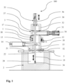
- Fig. 1 schematically shows a cross-sectional front view of the principal setup of the cryogenic cooling device 100 according to an exemplary embodiment of the present invention.
- the cryogenic cooling device 100 comprises a load lock unit 1, a container 2 for a cryogenic liquid bath 20 and a transport unit 3 removably attached to the load lock unit 1, wherein the load lock unit 1 is arranged on top of the container 2 and the transport unit 3 is arranged on top of the load lock unit 1.
- the container 2 which is embodied as is a bucket-shaped foam container, is filled with liquid nitrogen as cryogenic liquid forming the cryogenic liquid bath 20.
- the container 2 comprises an upper circumferential surface 21 surrounding an upper opening 22 of the container 2.
- the load lock unit 1 is mounted on a mounting plate 5 which is arranged on the upper circumferential surface 21 of the container 2.
- the load lock unit 1 comprises load lock chamber 10 which is fixedly mounted to the mounting plate 5.
- the mounting plate 5 comprises an opening 52, such that the upper opening 22 of the container 2 is not entirely obstructed.
- the load lock chamber 10 comprises a lower opening 15 at the bottom of the load lock chamber 10, which is arranged above the upper opening 22 of the container 2 when the load lock chamber 10 is in position above the container 2.
- a first passageway 13 is formed between the interior of the load lock chamber 10 and the interior of the container 2.
- the load lock unit 1 further comprises a load lock valve 14, which is a pneumatic gate valve with a pneumatically actuated gate. When the load lock valve 14 is closed, the first passageway 13 is shut off and the interior of the load lock chamber 10 is closed off towards the interior of the container 2. When the load lock valve 14 is open, the first passageway 13 towards the container 2 is clear.
- the cryogenic cooling device 100 further comprises a transport unit 3 which is removably attached to the load lock unit 1.
- the transport unit 3 comprises a transport chamber 30 and a transport valve 31.
- the transport chamber 30 comprises an opening 37 to which the transport valve 31 is attached in an airtight and vacuum-tight manner in order to open and close the opening 37.
- the transport valve 31 is further used to removably attach the transport unit 3 to the load lock unit 1, more particularly to an upper opening 17 of the load lock chamber 10.
- the transport chamber 30 When the transport unit 3 is attached to the load lock unit 1, the transport chamber 30 is arranged together with the transport valve 31 on top of the load lock chamber 10 such that the opening 37 of the transport chamber 30 faces the upper opening 17 of the load lock chamber 10. Hence, when the transport valve 31 is open, a second passageway 32 is formed between the interior of the transport chamber 30 and the interior of the load lock chamber 10. Vice versa, when the transport valve 31 is closed, the second passageway 32 is shut off to close off the transport chamber 30 in a sealing manner.
- the transport valve 31 is a manual gate valve, which advantageously does not require any external power source and thus allows to easily remove the transport unit 3 in a closed configuration from the load lock unit 1.
- the transport valve 31 is removably attached to the load lock chamber 10 via a quick release fastening mechanism 12.
- a quick release fastening mechanism 12 In a closed position of the quick release fastening mechanism 12, the transport unit 3 is pulled by the quick release fastening mechanism 12 towards the load lock chamber 10 and a connection between the transport valve 31 and the load lock chamber 10 is closed in a sealing manner by a sealing ring 16.
- the transport unit 3 further comprises a sample manipulator 33 which is mounted via a manipulator mount 36 to the transport chamber 30.
- the sample manipulator 33 further comprises a rod 35 with a sample holder 34 arranged at a distal tip of the rod 35.
- the manipulator mount 36 allows a movement of the rod in a vertical direction, such that the rod 35 is movable in a vertical direction (see black double-sided arrows) with respect to the manipulator mount 36 and thus the transport chamber 30.
- the manipulator mount 36 is mounted to the transport chamber 30 in a sealing manner and the rod 35 is movably mounted to the manipulator mount 36 in sealing manner, such that the interior of the transport chamber 30 is sealed against ambient air at the manipulator mount 36.
- the manipulator mount 36 comprises a mechanical feedthrough suitable for vacuum applications. It may have a locking device to hold the rod 35 in a fixed vertical position.
- the first passageway 13 and the second passageway 32 are clear and the sample holder 34 can be transferred by the rod 35 from the interior of the transport chamber 30 into the cryogenic liquid bath 20 in the container 2.
- the load lock chamber 10 further comprises a viewport 18 with a glass window.
- An optical sensor (not shown in the figures) can be arranged at the viewport 18 to provide feedback regarding the vertical position of the rod 35.
- the signal of the optical sensor can be provided to a controller of the load lock valve 14 to prevent that the load lock valve 14 is closed when a portion of the rod 35 or the sample holder 34 is arranged in the first passageway 13.
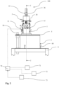
- Fig. 2 schematically shows a side view of the embodiment of the cryogenic cooling device 100 shown in Fig. 1 as well as a scheme of related gas connections.
- the line I-I indicates the cross-sectional plane of Fig. 1 .
- Fig. 3 (not to scale) schematically shows a back view of the of the embodiment of the cryogenic cooling device 100 shown in Fig. 1 and Fig. 2 .
- the container 2 is arranged on a mounting table 6 with a mounting pin 50 mounted thereto.
- the mounting plate 5 is swivel-mounted to the mounting pin 50, such that the mounting plate 5, the load lock unit 1 and the transport unit 3, if attached to the load lock unit 1, are swivelable aside to uncover the upper opening 22 of the container 2.
- the container 2 is kept in place by a plurality of table pins 60 when the mounting plate 5 is swiveled aside.
- the load lock unit 1 comprises a gas port 11 as gas inlet and gas outlet.
- the gas port 11 is connected (see dashed lines) to a valve bloc 70.
- the valve bloc 70 is in turn connected to a scroll pump 71 that allows evacuation of the load lock chamber 10 via the gas port 11 and also of the transport chamber 30, if it is attached to the load lock unit 1 and if the transport valve 31 is open.
- the valve bloc 70 is further connected (see dashed line) to a nitrogen gas supply 72 used as dry gas supply that allows providing dry nitrogen gas to the load lock chamber 10 in order to purge the load lock chamber 10 and, if attached and transport valve 31 is open, the transport chamber 30 via the gas port 11.
- the valve bloc 70 is connected to a controller 73.
- the controller 73 allows for the control of one or more valves of connections of the valve bloc to the gas port, the scroll pump 71 and the nitrogen gas supply 72, such that the gas flow into the load lock chamber 10 and the suction of gas out of the load lock chamber 10 via the gas port 11 can be controlled.
- the controller may be configured to control the valve bloc 70 to provide dry nitrogen gas to the load lock chamber 10 to maintain an overpressure in the in a range between 1.1 bar and 1.5 bar, in particular between 1.2 bar and 1.4 bar.
- the dry nitrogen gas is provided via gas port 11 and gas may leak out via the connection between the load lock chamber 10 and the container 2, in particular along the upper circumferential surface 21 where the mounting plate 5 is arranged on.
- liquid nitrogen is filled into the container 2 to provide a cryogenic liquid bath 20 in the container 2. This step may be performed when the mounting plate 5 is swiveled aside to uncover the upper opening 22 of the container 2. Subsequently, the mounting plate 5, the load lock unit 1 and the transport unit 3, if attached to the load lock unit 1 are be swiveled back to an arrangement on top of the container 2, such that the mounting plate 5 sits on the upper circumferential surface 21 of the container 2.
- the sample holder 34 holding the sample to be prepared is mounted to the distal end of the rod 35 of the sample manipulator 33. Then, the transport unit 3 is attached to the load lock unit 1.
- the connection between the transport valve 31 and the load lock chamber 10 is sealed by the sealing ring 16. Subsequently, the load lock valve 14 is closed to shut off the first passageway 13.
- the transport chamber 30 is evacuated via gas port 11 by the scroll pump 71. In case the transport chamber 30 needs to be evacuated as well, this step needs to be performed with the transport valve 31 open.
- the transport chamber 30 is purged with nitrogen gas.
- the load lock valve 14 is opened. Dry gas may be provided from the nitrogen gas supply 72 via the gas port 11 to the load lock chamber 10 to maintain an overpressure in the in a range between 1.1 bar and 1.5 bar, in particular between 1.2 bar and 1.4 bar.
- the transport valve 31 is open and the load lock valve 14 is open as well, said overpressure can be maintained to maintain a gas flow inside the load lock unit 1, container 2 and transport unit 3.
- the transport valve 31 In case the transport valve 31 is closed, it needs to be opened, such that both, the load lock valve 14 and the transport valve 31 are open and the first passageway 13 and the second passageway 32 are clear for transferring the sample holder 34 into the cryogenic liquid bath 20 in the container 2.
- the sample holder 34 with the sample mounted thereon can now be transferred using the sample manipulator 33 from the transport chamber 30 via the clear second passageway 32, the load lock chamber 10 and the clear first passageway 13 into the cryogenic liquid bath 20.
- a predetermined cooling time for example, in the range of 30 to 60... seconds, the sample holder 34 holding the sample can be removed again from the cryogenic liquid bath 20 using the sample manipulator 33.
- the sample holder 34 can be transferred from the container 2 via the clear first passageway 13, the load lock chamber 10 and the clear second passageway 32 into the transport chamber 30. Subsequently, the transport valve 31 can be closed to shut off the second passageway 32, thereby closing off the transport chamber 30 in a sealing manner.
- the quick release fastening mechanism 12 can be opened and the transport unit 3 can be detached from the load lock unit 1.
- the sample holder 34 holding the sample can then be transported in the closed transport unit 3 in an atmosphere of dry nitrogen gas to a different place, for example, to a structure determination setup.
- the load lock valve 14 can be closed to shut off the first passageway 13, and the transport chamber 30 as well as the load lock unit 1 can be evacuated prior to closing the transport valve 31.
- the sample holder 34 with the sample can then be transported in the closed transport unit 3 under vacuum to a different place, for example, to a structure determination setup.
Landscapes
- Physics & Mathematics (AREA)
- Health & Medical Sciences (AREA)
- Life Sciences & Earth Sciences (AREA)
- Chemical & Material Sciences (AREA)
- Analytical Chemistry (AREA)
- Biochemistry (AREA)
- General Health & Medical Sciences (AREA)
- General Physics & Mathematics (AREA)
- Immunology (AREA)
- Pathology (AREA)
Priority Applications (2)
| Application Number | Priority Date | Filing Date | Title |
|---|---|---|---|
| EP23192417.6A EP4513164A1 (de) | 2023-08-21 | 2023-08-21 | Kryogene kühlvorrichtung und verfahren zur kryogenen herstellung einer probe |
| PCT/EP2024/073343 WO2025040676A1 (en) | 2023-08-21 | 2024-08-20 | Cryogenic cooling device and method for cryogenic preparation of a sample |
Applications Claiming Priority (1)
| Application Number | Priority Date | Filing Date | Title |
|---|---|---|---|
| EP23192417.6A EP4513164A1 (de) | 2023-08-21 | 2023-08-21 | Kryogene kühlvorrichtung und verfahren zur kryogenen herstellung einer probe |
Publications (1)
| Publication Number | Publication Date |
|---|---|
| EP4513164A1 true EP4513164A1 (de) | 2025-02-26 |
Family
ID=87760338
Family Applications (1)
| Application Number | Title | Priority Date | Filing Date |
|---|---|---|---|
| EP23192417.6A Withdrawn EP4513164A1 (de) | 2023-08-21 | 2023-08-21 | Kryogene kühlvorrichtung und verfahren zur kryogenen herstellung einer probe |
Country Status (2)
| Country | Link |
|---|---|
| EP (1) | EP4513164A1 (de) |
| WO (1) | WO2025040676A1 (de) |
Citations (3)
| Publication number | Priority date | Publication date | Assignee | Title |
|---|---|---|---|---|
| US20090133410A1 (en) * | 2006-03-30 | 2009-05-28 | Thorne Robert E | System and method for increased cooling rates in rapid cooling of small biological samples |
| US7633290B1 (en) * | 2008-09-09 | 2009-12-15 | General Electric Company | Apparatus and method for a fully automated preparation of a hyperpolarizing imaging agent |
| US20170062174A1 (en) * | 2015-09-02 | 2017-03-02 | Hitachi High-Tech Science Corporation | Transport device, treatment device, vacuum device, and charged particle beam device |
-
2023
- 2023-08-21 EP EP23192417.6A patent/EP4513164A1/de not_active Withdrawn
-
2024
- 2024-08-20 WO PCT/EP2024/073343 patent/WO2025040676A1/en active Pending
Patent Citations (3)
| Publication number | Priority date | Publication date | Assignee | Title |
|---|---|---|---|---|
| US20090133410A1 (en) * | 2006-03-30 | 2009-05-28 | Thorne Robert E | System and method for increased cooling rates in rapid cooling of small biological samples |
| US7633290B1 (en) * | 2008-09-09 | 2009-12-15 | General Electric Company | Apparatus and method for a fully automated preparation of a hyperpolarizing imaging agent |
| US20170062174A1 (en) * | 2015-09-02 | 2017-03-02 | Hitachi High-Tech Science Corporation | Transport device, treatment device, vacuum device, and charged particle beam device |
Also Published As
| Publication number | Publication date |
|---|---|
| WO2025040676A1 (en) | 2025-02-27 |
Similar Documents
| Publication | Publication Date | Title |
|---|---|---|
| US7644637B2 (en) | Method and apparatus for transfer of samples in a controlled environment | |
| CN111684564B (zh) | 真空转移组件 | |
| US5145303A (en) | Method and apparatus for reducing particulate contamination in processing chambers | |
| CN110726746A (zh) | 一种用于跨平台连接的样品密封和真空转移装置 | |
| JPH04220504A (ja) | 生体試料観察用走査型トンネル顕微鏡 | |
| CN112505335B (zh) | 超高真空样品转移设备及转移方法 | |
| EP4220681A1 (de) | Inertgasprobentransfer für strahlsysteme | |
| EP4345862B1 (de) | Systeme und verfahren zur übertragung einer probe in und aus einer vakuumkammer eines transmissionselektronenmikroskops | |
| WO2025040676A1 (en) | Cryogenic cooling device and method for cryogenic preparation of a sample | |
| US20230045321A1 (en) | System for loading and/or manipulating a sample in a sample transfer device | |
| WO2022126840A1 (zh) | 一种扫描电镜样品盒系统及其打开方法 | |
| JP3239116B2 (ja) | 試料搬送装置 | |
| US20240274399A1 (en) | Device For Interfacing A Sample Transfer Device To An Analytic Or Sample Preparation Device And A Container For Transporting A Sample Under Environmentally Controlled Conditions | |
| JP2000215837A (ja) | 試料ホルダ | |
| US12431322B2 (en) | System and method for handling samples for study in a charged particle apparatus, such as a transmission electron microscope | |
| US12020895B2 (en) | Systems and apparatuses for contamination-free vacuum transfer of samples | |
| US4532816A (en) | Sample vessel | |
| JP2017050181A (ja) | 搬送装置、処理装置、真空装置および荷電粒子ビーム装置 | |
| US20220155193A1 (en) | System and method for handling cryo-charged particle samples | |
| US20230296639A1 (en) | Cryogenic sample handling and storage system | |
| JPH05128988A (ja) | 電子線装置 | |
| JP5530917B2 (ja) | 試料ホルダの排気方法及び装置 | |
| WO2025043189A2 (en) | Sample transfer apparatus for use with vacuum instruments | |
| JPH11213931A (ja) | 試料導入装置 | |
| US20240212972A1 (en) | Automated Multi-Grid Handling Apparatus |
Legal Events
| Date | Code | Title | Description |
|---|---|---|---|
| PUAI | Public reference made under article 153(3) epc to a published international application that has entered the european phase |
Free format text: ORIGINAL CODE: 0009012 |
|
| STAA | Information on the status of an ep patent application or granted ep patent |
Free format text: STATUS: THE APPLICATION HAS BEEN PUBLISHED |
|
| AK | Designated contracting states |
Kind code of ref document: A1 Designated state(s): AL AT BE BG CH CY CZ DE DK EE ES FI FR GB GR HR HU IE IS IT LI LT LU LV MC ME MK MT NL NO PL PT RO RS SE SI SK SM TR |
|
| STAA | Information on the status of an ep patent application or granted ep patent |
Free format text: STATUS: THE APPLICATION IS DEEMED TO BE WITHDRAWN |
|
| 18D | Application deemed to be withdrawn |
Effective date: 20250827 |