EP4516565A1 - Véhicule de chantier électrique - Google Patents
Véhicule de chantier électrique Download PDFInfo
- Publication number
- EP4516565A1 EP4516565A1 EP23795835.0A EP23795835A EP4516565A1 EP 4516565 A1 EP4516565 A1 EP 4516565A1 EP 23795835 A EP23795835 A EP 23795835A EP 4516565 A1 EP4516565 A1 EP 4516565A1
- Authority
- EP
- European Patent Office
- Prior art keywords
- motor
- rotation speed
- operation tool
- work vehicle
- electric work
- Prior art date
- Legal status (The legal status is an assumption and is not a legal conclusion. Google has not performed a legal analysis and makes no representation as to the accuracy of the status listed.)
- Pending
Links
Images





Classifications
-
- B—PERFORMING OPERATIONS; TRANSPORTING
- B60—VEHICLES IN GENERAL
- B60L—PROPULSION OF ELECTRICALLY-PROPELLED VEHICLES; SUPPLYING ELECTRIC POWER FOR AUXILIARY EQUIPMENT OF ELECTRICALLY-PROPELLED VEHICLES; ELECTRODYNAMIC BRAKE SYSTEMS FOR VEHICLES IN GENERAL; MAGNETIC SUSPENSION OR LEVITATION FOR VEHICLES; MONITORING OPERATING VARIABLES OF ELECTRICALLY-PROPELLED VEHICLES; ELECTRIC SAFETY DEVICES FOR ELECTRICALLY-PROPELLED VEHICLES
- B60L15/00—Methods, circuits, or devices for controlling the traction-motor speed of electrically-propelled vehicles
- B60L15/20—Methods, circuits, or devices for controlling the traction-motor speed of electrically-propelled vehicles for control of the vehicle or its driving motor to achieve a desired performance, e.g. speed, torque, programmed variation of speed
- B60L15/2054—Methods, circuits, or devices for controlling the traction-motor speed of electrically-propelled vehicles for control of the vehicle or its driving motor to achieve a desired performance, e.g. speed, torque, programmed variation of speed by controlling transmissions or clutches
-
- A—HUMAN NECESSITIES
- A01—AGRICULTURE; FORESTRY; ANIMAL HUSBANDRY; HUNTING; TRAPPING; FISHING
- A01B—SOIL WORKING IN AGRICULTURE OR FORESTRY; PARTS, DETAILS, OR ACCESSORIES OF AGRICULTURAL MACHINES OR IMPLEMENTS, IN GENERAL
- A01B63/00—Lifting or adjusting devices or arrangements for agricultural machines or implements
- A01B63/02—Lifting or adjusting devices or arrangements for agricultural machines or implements for implements mounted on tractors
- A01B63/10—Lifting or adjusting devices or arrangements for agricultural machines or implements for implements mounted on tractors operated by hydraulic or pneumatic means
- A01B63/111—Lifting or adjusting devices or arrangements for agricultural machines or implements for implements mounted on tractors operated by hydraulic or pneumatic means regulating working depth of implements
- A01B63/112—Lifting or adjusting devices or arrangements for agricultural machines or implements for implements mounted on tractors operated by hydraulic or pneumatic means regulating working depth of implements to control draught load, i.e. tractive force
-
- B—PERFORMING OPERATIONS; TRANSPORTING
- B60—VEHICLES IN GENERAL
- B60L—PROPULSION OF ELECTRICALLY-PROPELLED VEHICLES; SUPPLYING ELECTRIC POWER FOR AUXILIARY EQUIPMENT OF ELECTRICALLY-PROPELLED VEHICLES; ELECTRODYNAMIC BRAKE SYSTEMS FOR VEHICLES IN GENERAL; MAGNETIC SUSPENSION OR LEVITATION FOR VEHICLES; MONITORING OPERATING VARIABLES OF ELECTRICALLY-PROPELLED VEHICLES; ELECTRIC SAFETY DEVICES FOR ELECTRICALLY-PROPELLED VEHICLES
- B60L15/00—Methods, circuits, or devices for controlling the traction-motor speed of electrically-propelled vehicles
- B60L15/20—Methods, circuits, or devices for controlling the traction-motor speed of electrically-propelled vehicles for control of the vehicle or its driving motor to achieve a desired performance, e.g. speed, torque, programmed variation of speed
-
- B—PERFORMING OPERATIONS; TRANSPORTING
- B60—VEHICLES IN GENERAL
- B60L—PROPULSION OF ELECTRICALLY-PROPELLED VEHICLES; SUPPLYING ELECTRIC POWER FOR AUXILIARY EQUIPMENT OF ELECTRICALLY-PROPELLED VEHICLES; ELECTRODYNAMIC BRAKE SYSTEMS FOR VEHICLES IN GENERAL; MAGNETIC SUSPENSION OR LEVITATION FOR VEHICLES; MONITORING OPERATING VARIABLES OF ELECTRICALLY-PROPELLED VEHICLES; ELECTRIC SAFETY DEVICES FOR ELECTRICALLY-PROPELLED VEHICLES
- B60L15/00—Methods, circuits, or devices for controlling the traction-motor speed of electrically-propelled vehicles
- B60L15/20—Methods, circuits, or devices for controlling the traction-motor speed of electrically-propelled vehicles for control of the vehicle or its driving motor to achieve a desired performance, e.g. speed, torque, programmed variation of speed
- B60L15/2072—Methods, circuits, or devices for controlling the traction-motor speed of electrically-propelled vehicles for control of the vehicle or its driving motor to achieve a desired performance, e.g. speed, torque, programmed variation of speed for drive off
-
- B—PERFORMING OPERATIONS; TRANSPORTING
- B60—VEHICLES IN GENERAL
- B60L—PROPULSION OF ELECTRICALLY-PROPELLED VEHICLES; SUPPLYING ELECTRIC POWER FOR AUXILIARY EQUIPMENT OF ELECTRICALLY-PROPELLED VEHICLES; ELECTRODYNAMIC BRAKE SYSTEMS FOR VEHICLES IN GENERAL; MAGNETIC SUSPENSION OR LEVITATION FOR VEHICLES; MONITORING OPERATING VARIABLES OF ELECTRICALLY-PROPELLED VEHICLES; ELECTRIC SAFETY DEVICES FOR ELECTRICALLY-PROPELLED VEHICLES
- B60L2200/00—Type of vehicles
- B60L2200/40—Working vehicles
-
- B—PERFORMING OPERATIONS; TRANSPORTING
- B60—VEHICLES IN GENERAL
- B60L—PROPULSION OF ELECTRICALLY-PROPELLED VEHICLES; SUPPLYING ELECTRIC POWER FOR AUXILIARY EQUIPMENT OF ELECTRICALLY-PROPELLED VEHICLES; ELECTRODYNAMIC BRAKE SYSTEMS FOR VEHICLES IN GENERAL; MAGNETIC SUSPENSION OR LEVITATION FOR VEHICLES; MONITORING OPERATING VARIABLES OF ELECTRICALLY-PROPELLED VEHICLES; ELECTRIC SAFETY DEVICES FOR ELECTRICALLY-PROPELLED VEHICLES
- B60L2240/00—Control parameters of input or output; Target parameters
- B60L2240/40—Drive Train control parameters
- B60L2240/42—Drive Train control parameters related to electric machines
- B60L2240/421—Speed
-
- B—PERFORMING OPERATIONS; TRANSPORTING
- B60—VEHICLES IN GENERAL
- B60L—PROPULSION OF ELECTRICALLY-PROPELLED VEHICLES; SUPPLYING ELECTRIC POWER FOR AUXILIARY EQUIPMENT OF ELECTRICALLY-PROPELLED VEHICLES; ELECTRODYNAMIC BRAKE SYSTEMS FOR VEHICLES IN GENERAL; MAGNETIC SUSPENSION OR LEVITATION FOR VEHICLES; MONITORING OPERATING VARIABLES OF ELECTRICALLY-PROPELLED VEHICLES; ELECTRIC SAFETY DEVICES FOR ELECTRICALLY-PROPELLED VEHICLES
- B60L2240/00—Control parameters of input or output; Target parameters
- B60L2240/40—Drive Train control parameters
- B60L2240/42—Drive Train control parameters related to electric machines
- B60L2240/423—Torque
-
- B—PERFORMING OPERATIONS; TRANSPORTING
- B60—VEHICLES IN GENERAL
- B60L—PROPULSION OF ELECTRICALLY-PROPELLED VEHICLES; SUPPLYING ELECTRIC POWER FOR AUXILIARY EQUIPMENT OF ELECTRICALLY-PROPELLED VEHICLES; ELECTRODYNAMIC BRAKE SYSTEMS FOR VEHICLES IN GENERAL; MAGNETIC SUSPENSION OR LEVITATION FOR VEHICLES; MONITORING OPERATING VARIABLES OF ELECTRICALLY-PROPELLED VEHICLES; ELECTRIC SAFETY DEVICES FOR ELECTRICALLY-PROPELLED VEHICLES
- B60L2240/00—Control parameters of input or output; Target parameters
- B60L2240/40—Drive Train control parameters
- B60L2240/48—Drive Train control parameters related to transmissions
- B60L2240/486—Operating parameters
-
- B—PERFORMING OPERATIONS; TRANSPORTING
- B60—VEHICLES IN GENERAL
- B60L—PROPULSION OF ELECTRICALLY-PROPELLED VEHICLES; SUPPLYING ELECTRIC POWER FOR AUXILIARY EQUIPMENT OF ELECTRICALLY-PROPELLED VEHICLES; ELECTRODYNAMIC BRAKE SYSTEMS FOR VEHICLES IN GENERAL; MAGNETIC SUSPENSION OR LEVITATION FOR VEHICLES; MONITORING OPERATING VARIABLES OF ELECTRICALLY-PROPELLED VEHICLES; ELECTRIC SAFETY DEVICES FOR ELECTRICALLY-PROPELLED VEHICLES
- B60L2250/00—Driver interactions
- B60L2250/24—Driver interactions by lever actuation
-
- B—PERFORMING OPERATIONS; TRANSPORTING
- B60—VEHICLES IN GENERAL
- B60L—PROPULSION OF ELECTRICALLY-PROPELLED VEHICLES; SUPPLYING ELECTRIC POWER FOR AUXILIARY EQUIPMENT OF ELECTRICALLY-PROPELLED VEHICLES; ELECTRODYNAMIC BRAKE SYSTEMS FOR VEHICLES IN GENERAL; MAGNETIC SUSPENSION OR LEVITATION FOR VEHICLES; MONITORING OPERATING VARIABLES OF ELECTRICALLY-PROPELLED VEHICLES; ELECTRIC SAFETY DEVICES FOR ELECTRICALLY-PROPELLED VEHICLES
- B60L2250/00—Driver interactions
- B60L2250/26—Driver interactions by pedal actuation
Definitions
- the present invention relates to an electric work vehicle including a travel device driven by a motor.
- an electric tractor (an electric work vehicle) includes a travel device and a work vehicle both driven by a motor.
- the electric work vehicle such as an electric tractor includes various operation tools, and the motor or the like is controlled based on an operation on the various operation tools such that the electric work vehicle travels and works.
- Patent Literature 1 Japanese Unexamined Patent Application Publication No. 2013-150560
- the motor can stand by at a rotation speed of 0 rpm, and when an operation is performed in a wrong procedure with the motor being at the rotation speed of 0 rpm, a body of the electric work vehicle may suddenly move or may not be able to start traveling or working appropriately.
- An object of the present invention is to provide an electric work vehicle that can start traveling or working appropriately even while a motor is at a rotation speed of 0 rpm or rotates minutely.
- an electric work vehicle includes: a motor configured to drive at least either a travel device or a work device; at least one shift operation tool configured to shift a rotational power for driving the travel device or the work device; an accelerator operation tool configured to raise and lower a motor rotation speed of the motor; and a motor controlling section configured to control the motor rotation speed in response to an operation on the accelerator operation tool and to perform a motor restraining control to restrict an output from the motor in response to the at least one shift operation tool and the accelerator operation tool being operated in an inappropriate procedure with the motor rotation speed being equal to or less than a predetermined first rotation speed.
- the motor restraining control may be a control to restrict an increase in the motor rotation speed.
- the motor restraining control may be a control to restrict an increase in a torque of the motor.
- the motor controlling section may perform the motor restraining control in response to the accelerator operation tool being operated after the at least one shift operation tool is operated with the motor rotation speed being equal to or less than the first rotation speed.
- the first rotation speed may be 0 rotations.
- the motor restraining control may be a control to restrain the motor rotation speed from increasing.
- the motor restraining control may be a control to set an upper limit allowable for the motor rotation speed to a predetermined idling rotation speed larger than 0 rotations.
- the upper limit of the motor rotation speed is restricted to the idling rotation speed at which the travel device and the work device barely work, so that an increase in the motor rotation speed is restrained. Accordingly, it is possible to restrain the body from suddenly moving or the work device from suddenly working, so that travel or work can be started appropriately.
- the rotation speed of the motor increases moderately, and this allows an operator to recognize, by motor sound, that the motor is in operation. Accordingly, the operator can intentionally operate the shift operation tool and the accelerator operation tool in an appropriate procedure, so that travel or work can be started appropriately.
- the motor restraining control may be a control to set the motor rotation speed to a predetermined second rotation speed larger than the first rotation speed, in response to the at least one shift operation tool being operated with the motor rotation speed being equal to or less than the first rotation speed.
- the motor rotation speed is set to the second rotation speed, so that the motor rotation speed is raised in advance. Accordingly, even when the accelerator operation tool is operated, it is possible to restrain the motor rotation speed from increasing rapidly. As a result, it is possible to restrain the body from suddenly moving or the work device from suddenly working, so that travel or work can be started appropriately.
- the operator can recognize, by motor sound, that the motor is in operation. Accordingly, the operator can intentionally operate the shift operation tool and the accelerator operation tool in an appropriate procedure, so that travel or work can be started appropriately.
- the motor restraining control may be a control to raise the motor rotation speed at a predetermined acceleration or less.
- the motor controlling section may stop the motor restraining control in response to the shift operation tool being restored.
- the motor controlling section may stop the motor restraining control in response to the shift operation tool being restored and the motor rotation speed becoming 0 rotations.
- An electric work vehicle includes: a motor configured to drive at least either a travel device or a work device; at least one shift operation tool configured to shift a rotational power for driving the travel device or the work device; an accelerator operation tool configured to raise and lower a motor rotation speed of the motor; and a motor controlling section configured to control the motor rotation speed in response to an operation on the accelerator operation tool, and the electric work vehicle is configured to perform predetermined notification while the motor is in operation.
- the predetermined notification is performed while the motor is in operation. This allows an operator to recognize that the motor is in operation. This restrains the motor from being wrongly recognized to be stopped though the motor works at a low rotation speed, and the operator can intentionally operate the shift operation tool and the accelerator operation tool in an appropriate procedure. As a result, travel or work can be started appropriately.
- the notification may be performed while the motor rotation speed is 0 rotations or equal to or less than a predetermined first rotation speed after the at least one shift operation tool is operated.
- a power transmission mechanism configured to transmit power from the motor to the travel device or the work device.
- the notification is performed in a case where the motor rotation speed is 0 rotations or the motor barely rotates after the shift operation tool is operated, and hereby, the operator can recognize that the motor M is in operation. As a result, the operator can intentionally operate the shift operation tool and the accelerator operation tool in an appropriate procedure, so that travel or work can be started appropriately.
- the motor controlling section may set the motor rotation speed equal to or less than a predetermined second rotation speed larger than the first rotation speed, in response to the at least one shift operation tool being operated with the motor rotation speed being equal to or less than the first rotation speed, and the notification may be performed by rotary sound of the motor.
- the motor rotation speed is set to the second rotation speed, so that the motor generates motor sound.
- the operator can recognize, by motor sound, that the motor is in operation. Accordingly, the operator can intentionally operate the shift operation tool and the accelerator operation tool in an appropriate procedure, so that travel or work can be started appropriately.
- the motor controlling section may control the motor rotation speed not to become larger than an idling rotation speed that is a predetermined rotation speed larger than 0 rounds while the motor is in operation, and the notification may be performed by rotary sound of the motor.
- the motor rotation speed is set equal to or less than the idling rotation speed at which the travel device and the work device barely work, so that motor sound is generated from the motor.
- the operator can recognize, by motor sound, that the motor is in operation. Accordingly, the operator can intentionally operate the shift operation tool and the accelerator operation tool in an appropriate procedure, so that travel or work can be started appropriately.
- the electric work vehicle may further include a notifier configured to perform the notification.
- the operator can recognize that the motor is in operation. Accordingly, the operator can intentionally operate the shift operation tool and the accelerator operation tool in an appropriate procedure, so that travel or work can be started appropriately.
- the notifier may be a speaker configured to emit beep sound, and the notification may be performed by the beep sound.
- the operator can recognize, by the beep sound, that the motor is in operation. Accordingly, the operator can intentionally operate the shift operation tool and the accelerator operation tool in an appropriate procedure, so that travel or work can be started appropriately.
- the notifier may be an alarm lamp, and the notification may be performed by lighting or flashing the alarm lamp.
- the operator can recognize, by the lighting or flashing of the alarm lamp, that the motor is in operation. Accordingly, the operator can intentionally operate the shift operation tool and the accelerator operation tool in an appropriate procedure, so that travel or work can be started appropriately.
- the electric work vehicle may further include a hydrostatic continuously variable transmission configured to shift the rotational power to be transmitted from the motor to the travel device, and the at least one shift operation tool may include an HST operation tool configured to operate an angle of a cam plate of the hydrostatic continuously variable transmission.
- the operator can recognize that the motor is in operation. Accordingly, the operator can intentionally operate the shift operation tool in an appropriate procedure, so that the body can start traveling appropriately.
- the at least one shift operation tool may include a PTO operation tool configured to shift the rotational power to be transmitted from the motor to the work device.
- the operator can recognize that the motor is in operation. Accordingly, the operator can intentionally operate the shift operation tool in an appropriate procedure, so that the work vehicle can start working appropriately.
- a direction of an arrow “F” in the drawings indicates “forward”
- a direction of an arrow “B” indicates “rearward”
- a direction of an arrow “L” indicates “left”
- a direction of an arrow R indicates “right,” unless otherwise specified.
- a direction of an arrow “U” indicates “upward”
- a direction of an arrow “D” indicates “downward.”
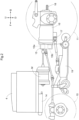
- the tractor includes right and left front wheels 10, right and left rear wheels 11, and a cover member 12.
- the tractor also includes a body frame 2 and a driving section 3.
- the body frame 2 is supported on the right and left front wheels 10 (corresponding to a "travel device") and the right and left rear wheels 11 (corresponding to a "travel device”).
- the cover member 12 is disposed in a front portion of a body.
- the driving section 3 is provided rearward of the cover member 12. In other words, the cover member 12 is disposed forward of the driving section 3.
- the driving section 3 includes a protection frame 30, a driver seat 31, and a steering wheel 32.
- An operator can be seated on the driver seat 31. This allows the operator to get in the driving section 3.
- the right and left front wheels 10 are steered by an operation on the steering wheel 32. The operator can perform various driving operations in the driving section 3.
- the tractor includes a drive battery 4.
- the cover member 12 is configured to be swingable around an opening-closing axis Q along the left-right direction of the body. Hereby, the cover member 12 is configured to be openable and closable. When the cover member 12 is closed, the drive battery 4 is covered with the cover member 12.
- the tractor includes an inverter 14 and a motor M (an electric machine).
- the drive battery 4 supplies electric power to the inverter 14.
- the inverter 14 converts direct-current power from the drive battery 4 into alternating-current power and supplies the alternating-current power to the motor M.
- the motor M is driven by the alternating-current power supplied from the inverter 14.
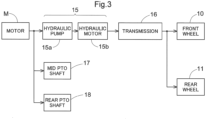
- the tractor includes a hydrostatic continuously variable transmission 15 and a transmission 16.
- the hydrostatic continuously variable transmission 15 includes a hydraulic pump 15a and a hydraulic motor 15b.
- the hydraulic pump 15a is driven by a rotational power from the motor M.
- a rotational power is output from the hydraulic motor 15b.
- the hydrostatic continuously variable transmission 15 is configured to shift the rotational power between the hydraulic pump 15a and the hydraulic motor 15b.
- the hydrostatic continuously variable transmission 15 is also configured to continuously vary a gear ratio.
- the rotational power output from the hydraulic motor 15b is transmitted to the transmission 16.
- the rotational power transmitted to the transmission 16 is shifted by a gear transmission mechanism of the transmission 16 and distributed to the right and left front wheels 10 and the right and left rear wheels 11.
- the right and left front wheels 10 and the right and left rear wheels 11 are driven.
- the tractor also includes a mid PTO shaft 17 and a rear PTO shaft 18 (hereinafter just referred to as a "PTO shaft” collectively in some cases).
- the rotational power output from the motor M is distributed to the hydraulic pump 15a, the mid PTO shaft 17, the rear PTO shaft 18.
- the mid PTO shaft 17 and the rear PTO shaft 18 rotate.
- a work device When a work device is connected to the mid PTO shaft 17 or the rear PTO shaft 18, the work device is driven by the rotational power from the mid PTO shaft 17 or the rear PTO shaft 18.
- a mowing device 19 is connected to the mid PTO shaft 17. The mowing device 19 is driven by the rotational power from the mid PTO shaft 17.
- the driving section 3 includes various operation tools for travel or work.
- a main shift lever 34 for travel or work.
- an auxiliary shift lever 35 for example, an accelerator lever 37 (corresponding to an “accelerator operation tool"), an HST pedal 38 (corresponding to a "shift operation tool” or an “HST operation tool”), and a PTO lever 39 (corresponding to a "shift operation tool” or a “PTO operation tool”) are provided.
- these operation tools will be described as a lever or a pedal but may be operation tools in given forms.
- the main shift lever 34 and the auxiliary shift lever 35 are provided on a left side of the driver seat 31 and are used for an operation to set a vehicle travel speed in forward movement and reverse movement.
- the accelerator lever 37 is provided on a right side of the steering wheel 32 and is used to operate raising and lowering of a rotation speed of the motor M.
- the PTO lever 39 is provided on the left side of the driver seat 31 and is used to shift the rotational power of the PTO shaft.
- the HST pedal 38 is provided on a right front side of the driver seat 31, on the floor of the driving section 3.
- the HST pedal 38 is operated by the right foot of an operator seated on the driver seat 31 and is used to start forward movement and reverse movement and to adjust the vehicle travel speed.
- the vehicle travel speed in this case is limited within a vehicle travel speed set by the main shift lever 34 and the auxiliary shift lever 35.
- the HST pedal 38 When the HST pedal 38 is tilted rearward from the neutral position, the angle of the cam plate of the hydrostatic continuously variable transmission 15 is changed, so that the body reverses.
- the HST pedal 38 can operate the vehicle travel speed depending on the amount of forward or rearward tilting.
- the main shift lever 34 and the auxiliary shift lever 35 are first operated with the motor M being in operation, so as to set a highest vehicle speed in forward movement or reverse movement. Subsequently, the accelerator lever 37 is operated such that the rotation speed of the motor M is adjusted to a rotation speed suitable for travel and work. Then, the HST pedal 38 is operated, so that the body starts to travel.
- the hydrostatic continuously variable transmission 15 restrains the rotational power of the motor M from being suddenly transmitted to the wheels (the front wheels 10 and the rear wheels 11), thereby retraining the body from suddenly moving.
- the PTO lever 39 is operated after the accelerator lever 37 is operated to adjust the rotation speed of the motor M, so that a rotational power suitable for work is output to the PTO shaft.
- the hydrostatic continuously variable transmission 15 restrains the rotational power of the motor M from being suddenly transmitted to a work device, thereby retraining the work device from suddenly working.
- the body may not be able to start to travel appropriately, or the work device may not be able to work appropriately.
- the accelerator lever 37 is operated after the HST pedal 38 is operated, the rotational power of the motor M is suddenly (directly) transmitted to the wheels (the front wheels 10 and the rear wheels 11), so that the body might suddenly move unintentionally.
- the accelerator lever 37 is operated after the PTO lever 39 is operated, the rotational power of the motor M is suddenly (directly) transmitted to the work device, so that the work device might suddenly work unintentionally.
- First described is a configuration to restrain inappropriate travel and work by controlling an output from the motor M based on FIGS. 5 to 7 with reference to FIGS. 3 , 4 .
- the tractor according to Embodiment 1 performs a predetermined motor restraining control so as to restrain inappropriate travel and work.
- the control unit 50 controls the motor restraining control.
- the control unit 50 includes a processor such as a CPU or an ECU and works in response to a control performed by the processor.
- the control unit 50 is connected to operation tools such as the main shift lever 34, the auxiliary shift lever 35, the accelerator lever 37, the HST pedal 38, and the PTO lever 39 and controls the motor M, the hydrostatic continuously variable transmission 15, and the transmission 16 based on respective operation states of these operation tools.
- the motor M drives the wheels (the front wheels 10 and the rear wheels 11) and the PTO shafts (the mid PTO shaft 17 and the rear PTO shaft 18), as described above.
- the control unit 50 may be connected to a notifier 26, and in this case, the control unit 50 causes the notifier 26 to perform predetermined notification.
- the control unit 50 includes an operation acquisition section 52 and a motor controlling section 54. In a case where the notifier 26 is provided, the control unit 50 further includes a notification controlling section 55.
- the operation acquisition section 52 acquires information on operations performed on the operation tools such as the main shift lever 34, the auxiliary shift lever 35, the accelerator lever 37, the HST pedal 38, and the PTO lever 39. More specifically, the operation acquisition section 52 acquires information on operation positions of the operation tools, or the like.
- the motor controlling section 54 controls an output from the motor M such as a motor rotation speed or a torque of the motor M, based on the information on the operations performed on the operation tools which information is acquired by the operation acquisition section 52. In a case where the accelerator operation tool, the HST pedal 38, and the PTO lever 39 are operated in an inappropriate procedure, the motor controlling section 54 performs a control to restrict an increase in the output of the motor M as the predetermined motor restraining control.
- the notification controlling section 55 causes the notifier 26 to perform predetermined notification and notifies that the motor restraining control is performed, for example.
- the main shift lever 34 and the auxiliary shift lever 35 are operated first. Subsequently, the accelerator lever 37 (the accelerator operation tool) is operated such that the motor rotation speed of the motor M is adjusted. As an appropriate procedure, the accelerator lever 37 (the accelerator operation tool) is operated, and after that, the HST pedal 38 and the PTO lever 39 (the shift operation tools) are operated to respective positions suitable for work travel.
- the following describes a step of performing the motor restraining control in a case where the operation tools are not operated appropriately.
- the accelerator lever 37 (the accelerator operation tool) is not operated, and the HST pedal 38 and the PTO lever 39 (the shift operation tools) are operated to respective positions suitable for work travel (step #1 in FIG. 6 ).
- the motor controlling section 54 determines whether or not the motor rotation speed is 0 rotations (0 rotations/m (rpm)) (step #2 in FIG. 6 ). That is, in an appropriate procedure, the accelerator lever 37 (the accelerator operation tool) is operated, and after that, the HST pedal 38 and the PTO lever 39 (the shift operation tools) are operated. In view of this, the motor controlling section 54 checks whether or not at least either the HST pedal 38 or the PTO lever 39 (the shift operation tool) is performed with the accelerator lever 37 (the accelerator operation tool) being not operated. In a case where the motor rotation speed is 0 rotations (Yes in step #2 in FIG. 6 ), the motor controlling section 54 checks whether or not the accelerator lever 37 (the accelerator operation tool) is operated (step #3 in FIG. 6 ). Hereby, the motor controlling section 54 checks whether or not the accelerator lever 37 (the accelerator operation tool) is operated (is operated in an inappropriate procedure) after the HST pedal 38 and the PTO lever 39 (the shift operation tools) are operated with the motor rotation speed being 0 rotations.
- the motor controlling section 54 restricts an increase in the motor rotation speed so as not to increase the motor rotation speed of the motor M from 0 rotations as the motor restraining control (step #4 in FIG. 6 ).
- FIG. 7 is a view illustrating an example of rotation speed transition that is the change of the motor rotation speed relative to a manipulated variable of the accelerator lever 37.
- the motor rotation speed changes in response to the manipulated variable of the accelerator lever 37 within an upper limit range corresponding to respective manipulated variables of the main shift lever 34 and the auxiliary shift lever 35, as indicated by a rotation speed transition LR0.
- the motor controlling section 54 ends the motor restraining control (step #6 in FIG. 6 ).
- the stop condition is that the HST pedal 38 and the PTO lever 39 are turned off (restored to their neutral positions). Note that the stop condition may be that the HST pedal 38 and the PTO lever 39 are turned off, and the accelerator lever 37 is restored to the position of 0 rotations.
- the tractor When the stop condition to end the motor restraining control is provided, the tractor is restored to a state where the tractor can receive an operation to cause the body to travel or to cause the work device to work, and when the operations are performed in an appropriate procedure after that, travel or work can be started appropriately.
- the motor controlling section 54 controls the motor M in response to the operation on the accelerator lever 37, the HST pedal 38, the PTO lever 39, and so on, in such a manner as to start work travel (step #7 in FIG. 6 ).
- Embodiment 2 a configuration in which, when the motor M is in operation, inappropriate travel and work is restrained by notifying that the motor M is in operation, based on FIGS. 5 , 7 , 8 with reference to FIGS. 3 , 4 .
- a tractor according to Embodiment 2 In order to restrain inappropriate travel and work, a tractor according to Embodiment 2 notifies that the motor M is in operation, while the motor M is in operation. Due to this notification, the operator recognizes that the motor M is in operation, so that the operator can intentionally cause the body to travel or the work device to work in an appropriate procedure. This consequently allows the operations to be performed in an appropriate procedure and restrains the body from suddenly moving or the work device from suddenly working, so that travel or work can be started appropriately.
- the main shift lever 34 and the auxiliary shift lever 35 are operated first. Then, the accelerator lever 37 (the accelerator operation tool) is operated such that the motor rotation speed of the motor M is adjusted. As an appropriate procedure, after the accelerator lever 37 (the accelerator operation tool) is operated, at least either the HST pedal 38 or the PTO lever 39 (the shift operation tool) is operated to a position suitable for work travel.
- the following describes a control performed by the tractor in a case where the operations are performed in an inappropriate procedure.
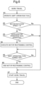
- the accelerator lever 37 (the accelerator operation tool) is not operated, and the HST pedal 38 and the PTO lever 39 (the shift operation tools) are operated to respective positions suitable for work travel (step #1 in FIG. 8 ).
- the motor controlling section 54 determines whether or not the motor rotation speed is 0 rotations (0 rotations/m (rpm)) (step #2 in FIG. 8 ). That is, in an appropriate procedure, the accelerator lever 37 (the accelerator operation tool) is operated, and after that, the HST pedal 38 and the PTO lever 39 (the shift operation tools) are operated. In view of this, the motor controlling section 54 checks whether or not at least either the HST pedal 38 or the PTO lever 39 (the shift operation tool) is performed with the accelerator lever 37 (the accelerator operation tool) being not operated.
- the notification controlling section 55 causes the notifier 26 to notify that the motor M is in operation (step #3 in FIG. 8 ).
- the operator who recognizes that the motor M is in operation changes the HST pedal 38 and the PTO lever 39 (the shift operation tools) to an OFF state (a neutral state) and operates the accelerator lever 37 (the accelerator operation tool), and after that, the operator operates at least either the HST pedal 38 or the PTO lever 39 (the shift operation tools) (step #4 in FIG. 8 ).
- work travel is subsequently started in response to the operation on the operation tool (step #5 in FIG. 8 ).
- appropriate work travel is also performed in a case where the motor rotation speed is not 0 rotations (0 rotations/m (rpm)) (the motor rotation speed increases) (No in step #2 in FIG. 8 ).
- the operator recognizes that the motor M is in operation, so that the operator can intentionally cause the body to travel or operate the work device in an appropriate procedure. This consequently allows the operations to be performed in an appropriate procedure and restrains the body from suddenly moving or the work device from suddenly working, so that travel or work can be started appropriately.
- the present invention is applicable to electrically-driven farm work vehicles such as a harvester and a rice transplanter, including a tractor, and various electric work vehicles that are electrically driven to travel and perform various works.
Landscapes
- Engineering & Computer Science (AREA)
- Mechanical Engineering (AREA)
- Power Engineering (AREA)
- Transportation (AREA)
- Life Sciences & Earth Sciences (AREA)
- Soil Sciences (AREA)
- Environmental Sciences (AREA)
- Electric Propulsion And Braking For Vehicles (AREA)
Applications Claiming Priority (3)
| Application Number | Priority Date | Filing Date | Title |
|---|---|---|---|
| JP2022074715A JP2023163666A (ja) | 2022-04-28 | 2022-04-28 | 電動作業車 |
| JP2022074716A JP7825504B2 (ja) | 2022-04-28 | 2022-04-28 | 電動作業車 |
| PCT/JP2023/003484 WO2023210087A1 (fr) | 2022-04-28 | 2023-02-03 | Véhicule de chantier électrique |
Publications (1)
| Publication Number | Publication Date |
|---|---|
| EP4516565A1 true EP4516565A1 (fr) | 2025-03-05 |
Family
ID=88518307
Family Applications (1)
| Application Number | Title | Priority Date | Filing Date |
|---|---|---|---|
| EP23795835.0A Pending EP4516565A1 (fr) | 2022-04-28 | 2023-02-03 | Véhicule de chantier électrique |
Country Status (3)
| Country | Link |
|---|---|
| US (1) | US20250033488A1 (fr) |
| EP (1) | EP4516565A1 (fr) |
| WO (1) | WO2023210087A1 (fr) |
Families Citing this family (1)
| Publication number | Priority date | Publication date | Assignee | Title |
|---|---|---|---|---|
| IT202300023826A1 (it) * | 2023-11-10 | 2025-05-10 | Carraro Spa | Gruppo di trasmissione per veicoli elettrici |
Family Cites Families (27)
| Publication number | Priority date | Publication date | Assignee | Title |
|---|---|---|---|---|
| JP4362426B2 (ja) * | 2004-09-15 | 2009-11-11 | 株式会社クボタ | 作業車の伝動構造 |
| JP2008029233A (ja) * | 2006-07-27 | 2008-02-14 | Yanmar Co Ltd | 芝刈機 |
| WO2010017242A1 (fr) * | 2008-08-05 | 2010-02-11 | Fallbrook Technologies Inc. | Procédés de commande d'une transmission et/ou d'une machine motrice |
| JP2010172207A (ja) * | 2009-01-27 | 2010-08-12 | Iseki & Co Ltd | 田植機 |
| JP2011122607A (ja) * | 2009-12-08 | 2011-06-23 | Denso Corp | 車両の制御装置 |
| JP2013001296A (ja) * | 2011-06-20 | 2013-01-07 | Denso Corp | 車両の後退速度規制装置 |
| JP5637126B2 (ja) * | 2011-12-02 | 2014-12-10 | トヨタ自動車株式会社 | 車両の駆動制御装置 |
| JP5943617B2 (ja) | 2012-01-24 | 2016-07-05 | 株式会社クボタ | 電動トラクタ |
| US8983691B2 (en) * | 2012-08-07 | 2015-03-17 | Deere & Company | Electric lawn tractor roll away prevention system |
| US9902272B2 (en) * | 2013-12-02 | 2018-02-27 | Nissan Motor Co., Ltd. | Control device for electric motor vehicle and control method for electric motor vehicle |
| JP2014144008A (ja) * | 2014-03-20 | 2014-08-14 | Yanmar Co Ltd | 農業用作業車両 |
| US10703215B2 (en) * | 2014-10-20 | 2020-07-07 | Ford Global Technologies, Llc | Hybrid powertrain speed control |
| US9759313B2 (en) * | 2014-11-26 | 2017-09-12 | Polaris Industries Inc. | Electronic shifting of a transmission |
| US10710463B2 (en) * | 2015-05-26 | 2020-07-14 | Nissan Motor Co., Ltd. | Control device for electric vehicle and control method for electric vehicle |
| DE102016200336A1 (de) * | 2016-01-14 | 2017-07-20 | Zf Friedrichshafen Ag | Verfahren zum Betreiben eines Fahrzeugantriebsstranges einer Arbeitsmaschine mit einer Antriebsmaschine, mit einem Getriebe und mit einem Abtrieb |
| CN108885473B (zh) * | 2016-03-30 | 2021-05-14 | 深圳市大疆创新科技有限公司 | 用于控制电机的方法和系统 |
| GB201720470D0 (en) * | 2017-12-08 | 2018-01-24 | Agco Int Gmbh | Utility vehicle braking |
| JP7069735B2 (ja) * | 2018-01-15 | 2022-05-18 | トヨタ自動車株式会社 | 自動車 |
| JP7001540B2 (ja) * | 2018-05-18 | 2022-01-19 | 株式会社クボタ | 作業車 |
| JP2020162282A (ja) * | 2019-03-26 | 2020-10-01 | ヤンマーパワーテクノロジー株式会社 | 作業車両 |
| US11654778B2 (en) * | 2020-03-06 | 2023-05-23 | Nissan Motor Co., Ltd. | Electric vehicle control method and electric vehicle control device |
| JP7394690B2 (ja) * | 2020-04-01 | 2023-12-08 | 北越工業株式会社 | 無限軌道型高所作業車の走行操作装置 |
| JP7377170B2 (ja) * | 2020-06-12 | 2023-11-09 | 株式会社クボタ | 作業車両 |
| KR102895282B1 (ko) * | 2020-12-01 | 2025-12-04 | 현대자동차주식회사 | 차량의 가상 변속감 구현 장치 및 방법 |
| US20230226927A1 (en) * | 2022-01-19 | 2023-07-20 | Lordstown EV Corporation | Dynamic torque allocation and efficiency control for electric vehicle |
| US20230226926A1 (en) * | 2022-01-19 | 2023-07-20 | Lordstown EV Corporation | Dynamic torque allocation and stability control for electric vehicle |
| EP4252520A1 (fr) * | 2022-03-31 | 2023-10-04 | Kanzaki Kokyukoki Mfg. Co., Ltd. | Véhicule de travail électrique |
-
2023
- 2023-02-03 EP EP23795835.0A patent/EP4516565A1/fr active Pending
- 2023-02-03 WO PCT/JP2023/003484 patent/WO2023210087A1/fr not_active Ceased
-
2024
- 2024-10-16 US US18/916,889 patent/US20250033488A1/en active Pending
Also Published As
| Publication number | Publication date |
|---|---|
| WO2023210087A1 (fr) | 2023-11-02 |
| US20250033488A1 (en) | 2025-01-30 |
Similar Documents
| Publication | Publication Date | Title |
|---|---|---|
| US10753460B2 (en) | Electronic control of a transmission | |
| EP3777507A1 (fr) | Véhicule de travail et tondeuse à gazon | |
| EP4397520A1 (fr) | Véhicule de travail | |
| KR20180130100A (ko) | 가변 엔진 속도 제어 | |
| US20250033488A1 (en) | Electric work vehicle | |
| US20240317049A1 (en) | Electric work vehicle | |
| JP2003312528A (ja) | 作業車の操向装置 | |
| JP2003129879A (ja) | トラクタの走行制御方法 | |
| JP7825504B2 (ja) | 電動作業車 | |
| JP2019206873A (ja) | ホイール式作業機械 | |
| ES2716847T3 (es) | Cambio automático de caja de cambios mecánica | |
| JP5534573B2 (ja) | 作業機 | |
| JP2023163666A (ja) | 電動作業車 | |
| US11801840B2 (en) | Work vehicle, control method, and recording medium | |
| EP2949971B1 (fr) | Véhicule de travail | |
| CA3003485A1 (fr) | Controle electronique d'une transmission | |
| US20240367523A1 (en) | Electric work vehicle | |
| JP7645786B2 (ja) | 電動作業車 | |
| JP7482766B2 (ja) | 作業車 | |
| JP2019195284A (ja) | 作業車 | |
| JP7369072B2 (ja) | トラクタ | |
| US10934950B2 (en) | System and method to control powertrain during directional shift | |
| JP6063493B2 (ja) | 移動農機 | |
| JP2023097055A (ja) | 電動作業車 | |
| JP2024178656A (ja) | 作業車両 |
Legal Events
| Date | Code | Title | Description |
|---|---|---|---|
| STAA | Information on the status of an ep patent application or granted ep patent |
Free format text: STATUS: THE INTERNATIONAL PUBLICATION HAS BEEN MADE |
|
| PUAI | Public reference made under article 153(3) epc to a published international application that has entered the european phase |
Free format text: ORIGINAL CODE: 0009012 |
|
| STAA | Information on the status of an ep patent application or granted ep patent |
Free format text: STATUS: REQUEST FOR EXAMINATION WAS MADE |
|
| 17P | Request for examination filed |
Effective date: 20241017 |
|
| AK | Designated contracting states |
Kind code of ref document: A1 Designated state(s): AL AT BE BG CH CY CZ DE DK EE ES FI FR GB GR HR HU IE IS IT LI LT LU LV MC ME MK MT NL NO PL PT RO RS SE SI SK SM TR |
|
| DAV | Request for validation of the european patent (deleted) | ||
| DAX | Request for extension of the european patent (deleted) | ||
| RIC1 | Information provided on ipc code assigned before grant |
Ipc: B60L 15/20 20060101AFI20260304BHEP Ipc: A01B 63/112 20060101ALI20260304BHEP |