EP4516604A1 - Procédé et appareil de commande de force de freinage de véhicule, support d'informations et véhicule - Google Patents
Procédé et appareil de commande de force de freinage de véhicule, support d'informations et véhicule Download PDFInfo
- Publication number
- EP4516604A1 EP4516604A1 EP24187226.6A EP24187226A EP4516604A1 EP 4516604 A1 EP4516604 A1 EP 4516604A1 EP 24187226 A EP24187226 A EP 24187226A EP 4516604 A1 EP4516604 A1 EP 4516604A1
- Authority
- EP
- European Patent Office
- Prior art keywords
- braking force
- vehicle
- wheel
- wheels
- compensatory
- Prior art date
- Legal status (The legal status is an assumption and is not a legal conclusion. Google has not performed a legal analysis and makes no representation as to the accuracy of the status listed.)
- Pending
Links
Images

Classifications
-
- B—PERFORMING OPERATIONS; TRANSPORTING
- B60—VEHICLES IN GENERAL
- B60T—VEHICLE BRAKE CONTROL SYSTEMS OR PARTS THEREOF; BRAKE CONTROL SYSTEMS OR PARTS THEREOF, IN GENERAL; ARRANGEMENT OF BRAKING ELEMENTS ON VEHICLES IN GENERAL; PORTABLE DEVICES FOR PREVENTING UNWANTED MOVEMENT OF VEHICLES; VEHICLE MODIFICATIONS TO FACILITATE COOLING OF BRAKES
- B60T8/00—Arrangements for adjusting wheel-braking force to meet varying vehicular or ground-surface conditions, e.g. limiting or varying distribution of braking force
- B60T8/17—Using electrical or electronic regulation means to control braking
- B60T8/176—Brake regulation specially adapted to prevent excessive wheel slip during vehicle deceleration, e.g. ABS
- B60T8/1766—Proportioning of brake forces according to vehicle axle loads, e.g. front to rear of vehicle
-
- B—PERFORMING OPERATIONS; TRANSPORTING
- B60—VEHICLES IN GENERAL
- B60T—VEHICLE BRAKE CONTROL SYSTEMS OR PARTS THEREOF; BRAKE CONTROL SYSTEMS OR PARTS THEREOF, IN GENERAL; ARRANGEMENT OF BRAKING ELEMENTS ON VEHICLES IN GENERAL; PORTABLE DEVICES FOR PREVENTING UNWANTED MOVEMENT OF VEHICLES; VEHICLE MODIFICATIONS TO FACILITATE COOLING OF BRAKES
- B60T13/00—Transmitting braking action from initiating means to ultimate brake actuator with power assistance or drive; Brake systems incorporating such transmitting means, e.g. air-pressure brake systems
- B60T13/74—Transmitting braking action from initiating means to ultimate brake actuator with power assistance or drive; Brake systems incorporating such transmitting means, e.g. air-pressure brake systems with electrical assistance or drive
- B60T13/746—Transmitting braking action from initiating means to ultimate brake actuator with power assistance or drive; Brake systems incorporating such transmitting means, e.g. air-pressure brake systems with electrical assistance or drive and mechanical transmission of the braking action
-
- B—PERFORMING OPERATIONS; TRANSPORTING
- B60—VEHICLES IN GENERAL
- B60T—VEHICLE BRAKE CONTROL SYSTEMS OR PARTS THEREOF; BRAKE CONTROL SYSTEMS OR PARTS THEREOF, IN GENERAL; ARRANGEMENT OF BRAKING ELEMENTS ON VEHICLES IN GENERAL; PORTABLE DEVICES FOR PREVENTING UNWANTED MOVEMENT OF VEHICLES; VEHICLE MODIFICATIONS TO FACILITATE COOLING OF BRAKES
- B60T8/00—Arrangements for adjusting wheel-braking force to meet varying vehicular or ground-surface conditions, e.g. limiting or varying distribution of braking force
- B60T8/17—Using electrical or electronic regulation means to control braking
- B60T8/172—Determining control parameters used in the regulation, e.g. by calculations involving measured or detected parameters
-
- B—PERFORMING OPERATIONS; TRANSPORTING
- B60—VEHICLES IN GENERAL
- B60T—VEHICLE BRAKE CONTROL SYSTEMS OR PARTS THEREOF; BRAKE CONTROL SYSTEMS OR PARTS THEREOF, IN GENERAL; ARRANGEMENT OF BRAKING ELEMENTS ON VEHICLES IN GENERAL; PORTABLE DEVICES FOR PREVENTING UNWANTED MOVEMENT OF VEHICLES; VEHICLE MODIFICATIONS TO FACILITATE COOLING OF BRAKES
- B60T8/00—Arrangements for adjusting wheel-braking force to meet varying vehicular or ground-surface conditions, e.g. limiting or varying distribution of braking force
- B60T8/17—Using electrical or electronic regulation means to control braking
- B60T8/176—Brake regulation specially adapted to prevent excessive wheel slip during vehicle deceleration, e.g. ABS
- B60T8/1761—Brake regulation specially adapted to prevent excessive wheel slip during vehicle deceleration, e.g. ABS responsive to wheel or brake dynamics, e.g. wheel slip, wheel acceleration or rate of change of brake fluid pressure
- B60T8/17616—Microprocessor-based systems
-
- Y—GENERAL TAGGING OF NEW TECHNOLOGICAL DEVELOPMENTS; GENERAL TAGGING OF CROSS-SECTIONAL TECHNOLOGIES SPANNING OVER SEVERAL SECTIONS OF THE IPC; TECHNICAL SUBJECTS COVERED BY FORMER USPC CROSS-REFERENCE ART COLLECTIONS [XRACs] AND DIGESTS
- Y02—TECHNOLOGIES OR APPLICATIONS FOR MITIGATION OR ADAPTATION AGAINST CLIMATE CHANGE
- Y02T—CLIMATE CHANGE MITIGATION TECHNOLOGIES RELATED TO TRANSPORTATION
- Y02T10/00—Road transport of goods or passengers
- Y02T10/60—Other road transportation technologies with climate change mitigation effect
- Y02T10/72—Electric energy management in electromobility
Definitions
- the present invention or disclosure relates to the technical field of vehicles, in particular to a method and apparatus for controlling a braking force of a vehicle, a storage medium, and a vehicle.
- a booster assists the driver in pushing a brake fluid from a master cylinder to a wheel cylinder.
- the wheel cylinder pushes a friction pad to clamp a brake disc, thus performing a brake function.
- the present invention provides a method and apparatus for controlling a braking force of a vehicle, a storage medium, and a vehicle.
- a method for controlling a braking force of a vehicle includes:
- computing the braking force loss value of the vehicle according to the first braking force, and the second braking force before the first wheel triggers the ABS function includes:
- increasing the braking force of the second wheel through the electronic mechanical brake system of the vehicle based on the braking force loss value includes:
- determining the compensatory braking force based on the braking force loss value includes:
- obtaining the compensatory braking force of the second wheels by distributing the lost braking force to the second wheels includes: obtaining the compensatory braking force of the second wheels by evenly distributing the lost braking force to the second wheels.
- obtaining the compensatory braking force the of second wheels by distributing the lost braking force to the second wheels includes:
- an apparatus for controlling a braking force of a vehicle includes:
- the first computation module includes:
- the first execution module includes:
- the third execution sub-module includes:
- the third execution sub-unit is configured to: obtain the compensatory braking force of the second wheels by evenly distributing the lost braking force to the second wheels.
- the third execution sub-unit is configured to:
- a vehicle includes:
- a non-transitory computer-readable storage medium stores a computer program instruction, where the program instruction implements steps of the method according to any one in the first aspect when performed by one or more processors.
- the first braking force of the first wheel may be obtained in response to determining that the first wheel of the vehicle triggers the ABS function.
- the braking force loss value of the vehicle may be computed according to the first braking force, and the second braking force before the first wheel triggers the ABS function. In this way, a braking force loss caused by triggering the ABS function of the vehicle may be computed.
- the braking force of the second wheel may be increased through the electronic mechanical brake system of the vehicle based on the braking force loss value, the second wheel being one or more wheels that do not trigger the ABS function of the vehicle.
- a working principle may be described as follows: when a brake pedal is pressed by a driver, a booster assists the driver in pushing brake fluid from a master cylinder to a wheel cylinder. Under pressure, the wheel cylinder pushes a friction pad to clamp a brake disc, thus performing a brake function.
- the pressure of the master cylinder is equal to the pressure of wheel cylinders of four wheels.
- one or more wheels may be locked due to a high braking pressure or a low road adhesion coefficient.
- the ABS function is triggered.
- the ABS function keeps the wheels in a set slip rate range through threshold control or slip rate control, thus obtaining road friction force that is more in line with a control strategy.
- a locked wheel may actively reduce the pressure under the control of the ABS.
- a pressure of the master cylinder of the wheel that triggers the ABS function may be greater than the pressure of the wheel cylinder.
- the pressure of the master cylinder of a wheel that does not trigger the ABS function is still equal to the pressure of the wheel cylinder.
- brake fluid discharged from the wheel cylinder may flow into an accumulator when the ABS works because of the pipeline design. Then, a motor works to pump the fluid from the accumulator back to a brake circuit. The fluid entering the brake circuit may enter the wheel cylinder of the other wheel in the same brake circuit. It should be noted that since the fluid in the accumulator cannot provide braking force, a braking force loss may occur after the fluid flows into the accumulator.
- the brake system of the vehicle is X-type or II-type in general, such that the brake fluid can only be transferred in the same brake circuit. It should be understood that in this case, it is impossible to compensate for braking force of the wheels in the other brake circuit.
- a left front wheel and a right rear wheel of the vehicle are in one brake circuit, and a right front wheel and a left rear wheel are in one brake circuit.
- the left front wheel and the right rear wheel trigger the ABS function at the same time, the fluids discharged from the wheel cylinders cannot be transferred to the wheel cylinders of the right front wheel and the left rear wheel, such that compensation for the braking force cannot be implemented.
- the brake system in the relevant scenario may suffer a large braking force loss, and the braking performance and safety of the vehicle are reduced accordingly.
- an example of the present invention provides a method for controlling a braking force of a vehicle.
- the method may be performed by a control apparatus.
- the control apparatus may be a constituent portion of a vehicle, or may be arranged independently of the vehicle.
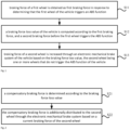
- Fig. 1 is a flowchart of a method for controlling the braking force of a vehicle according to an example of the present invention. With reference to Fig. 1 , the method includes steps 11, 12 and 13.
- braking force of a first wheel is obtained as first braking force in response to determining that the first wheel of the vehicle triggers an ABS function.
- a braking force loss value of the vehicle is computed according to the first braking force, and a second braking force before the first wheel triggers the ABS function.
- a difference between the first braking force and the second braking force may be computed, and the braking force loss value of the vehicle may be determined according to the difference.
- one or more wheels in the vehicle may trigger the ABS function.
- one or more first wheels may be provided.
- one first wheel is provided.
- the steps that a difference between the first braking force and the second braking force is computed, and the braking force loss value of the vehicle is determined according to the difference include:
- total braking force of the whole vehicle and braking force of each wheel may be determined according to drive demand.
- the ABS system intervenes and controls the braking force of the first wheel.
- the lost braking force of the vehicle may be determined.
- one first wheel is provided.
- the vehicle has one wheel triggering the ABS function.
- the difference between the first braking force and the second braking force may be computed, and the difference may be taken as the braking force loss value of the vehicle.
- the steps that a difference between the first braking force and the second braking force is computed, and the braking force loss value of the vehicle is determined according to the difference include:
- the braking force of the wheel before the ABS function is triggered and the braking force after the ABS function is triggered may be obtained.
- the braking force loss value caused by the wheel may be obtained by computing the difference between the braking force after the ABS function is triggered and the braking force before the ABS function is triggered.
- the braking force loss value of the vehicle may be obtained.
- braking force of a second wheel is increased through an electronic mechanical brake system of the vehicle based on the braking force loss value, the second wheel being one or more wheels that do not trigger the ABS function of the vehicle.
- the electronic mechanical brake system is a brake system based on electronic control. It does not have hydraulic pipe, and the braking pressure of the wheel is implemented with electrical signals. Thus, the electronic mechanical brake system may decouple the braking pressure of the wheel, and then control the braking force of each wheel independently.
- the braking force of the second wheel may be selectively increased through the electronic mechanical brake system of the vehicle.
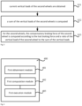
- Fig. 2 is an implementation flowchart of S13 in Fig. 1 shown according to an example of the present invention.
- the step that braking force of a second wheel is increased through an electronic mechanical brake system of the vehicle based on the braking force loss value includes steps 21 and 22.
- a compensatory braking force is determined according to the braking force loss value.
- the number of second wheels is one.
- braking force corresponding to the braking force loss value may be taken as the compensatory braking force.
- the lost braking force of the vehicle may be determined as 1000 N.
- the braking force corresponding to the braking force loss value may be taken as the compensatory braking force.
- the compensatory braking force is 1000 N.
- the 1000 N may be distributed to the wheel as the compensatory braking force of the wheel.
- the above solution can completely compensate for the lost braking force to the wheel that does not trigger the ABS.
- the braking force loss of the vehicle can be reduced.
- the number of second wheels is a plurality.
- the braking force corresponding to the braking force loss value may be taken as the compensatory braking force, and the compensatory braking force of the second wheels is determined by distributing the lost braking force to the second wheels.
- the lost braking force of the vehicle may be determined as 1000 N.
- the braking force corresponding to the braking force loss value may be taken as the compensatory braking force.
- the compensatory braking force is 1000 N.
- the 1000 N may be distributed to the plurality of wheels, and the compensatory braking force for each wheel may be determined accordingly.
- the above solution can completely compensate for the lost braking force of the wheel that does not trigger the ABS.
- the braking force loss of the vehicle can be reduced.
- the braking force is further distributed when compensation for the lost braking force to the wheels that do not trigger the ABS is implemented. In this way, the risk that the second wheel also triggers the ABS function due to the compensatory braking force is reduced.
- 1000 N may be equally distributed to the 3 second wheels.
- the compensatory braking force of the second wheel is computed according to the lost braking force and a ratio of the vertical load of the second wheel to the sum of the vertical loads.
- the compensatory braking force is 1000 N, and 3 second wheels are provided and denoted as A, B and C respectively.
- a current vertical load of A is denotes as X
- a current vertical load of B is denotes as Y
- a current vertical load of C is denotes as Z.
- the compensatory braking force of A is equal to 1000X/(X+Y+Z) in a unit of N.
- the compensatory braking force of B is 1000Y/(X+Y+Z) in a unit of N.
- the compensatory braking force of C is 1000Z/(X+Y+Z) in a unit of N.
- the compensatory braking force may be distributed according to the vertical loads of the second wheels.
- the utilization rate of the braking force can be improved through the distribution method.
- the braking force corresponding to the braking force loss value may be determined, and a product of the braking force and a target ratio may be used as the compensatory braking force.
- the target ratio may be selected as needed, such as 50%, 60% and 70%.
- S22 includes: the compensatory braking force is additionally distributed to the second wheel through the electronic mechanical brake system based on a current braking force of the second wheel.
- the compensatory braking force of A is 1000X/(X+Y+Z). Then, the braking force of 1000X/(X+Y+Z) may be additionally distributed to A through the electronic mechanical brake system, such that the braking force of A is equal to O+1000X/(X+Y+Z) in a unit of N.
- the braking force of B is denoted as P
- the current braking force of C is denoted as Q
- the braking force of B is equal to P+1000Y/(X+Y+Z)
- the braking force of C is Q+1000Z/(X+Y+Z).
- the braking force of wheels A, B and C is additionally increased by 1000 N, such that compensation for a decrease of 1000 N in the braking force due to triggering of the ABS by the first wheel can be implemented.
- the first braking force of the first wheel may be obtained in response to determining that the first wheel of the vehicle triggers the ABS function.
- the braking force loss value of the vehicle may be computed according to the first braking force, and the second braking force before the first wheel triggers the ABS function. In this way, a braking force loss caused by triggering the ABS function of the vehicle may be computed.
- the braking force of the second wheel may be increased through the electronic mechanical brake system of the vehicle based on the braking force loss value, the second wheel being one or more wheels that do not trigger the ABS function of the vehicle.
- Figs. 1-3 may be repeatedly performed many times. For example, after the braking force of 1000X/(X+Y+Z) is additionally distributed to A, if the wheel A triggers the ABS function, the above methods in Figs. 1-3 may be repeatedly performed. For example, when S11 in Fig. 1 is executed, a wheel A may also be used as a new first wheel. In addition, the wheel A is also taken into account when the braking force loss value of the vehicle is computed.
- Ft F FL +F FR +F RL +F RR
- F FL denotes braking force requested by the left front wheel
- F FR denotes braking force requested by the right front wheel
- F RL denotes braking force requested by the left rear wheel
- F RR denotes braking force requested by the right rear wheel.
- secondary distribution of braking force may be performed.
- the F Lost is distributed to other wheels.
- the F Lost may be evenly distributed to other wheels.
- the F Lost may also be distributed to other wheels according to vertical loads of other wheels.
- F Lost may be equally distributed to other wheels.
- Total lost braking force is F Lost
- the braking force of the vehicle after secondary distribution is still decreased by F Lost -F FRadd compared with Ft.
- the braking force may be distributed for the third time, so as to evenly distribute the decreased F Lost -F FRadd to the left rear wheel and the right rear wheel.
- FIG. 4 is a block diagram of an apparatus 400 for controlling the braking force of a vehicle according to the present invention.
- the apparatus 400 for controlling the braking force of a vehicle includes a first obtainment module 401, a first computation module 402 and a first execution module 403.
- the first obtainment module 401 configured to obtain braking force of a first wheel as first braking force in response to determining that the first wheel of the vehicle triggers an ABS function
- the first computation module 402 configured to compute a braking force loss value of the vehicle according to the first braking force, and a second braking force before the first wheel triggers the ABS function;
- the first execution module 403 configured to increase braking force of a second wheel through an electronic mechanical brake system of the vehicle based on the braking force loss value, the second wheel being one or more wheels that do not trigger the ABS function of the vehicle.
- the first braking force of the first wheel may be obtained in response to determining that the first wheel of the vehicle triggers the ABS function.
- the braking force loss value of the vehicle may be computed according to the first braking force, and the second braking force before the first wheel triggers the ABS function. In this way, a braking force loss caused by triggering the ABS function of the vehicle may be computed.
- the braking force of the second wheel may be increased through the electronic mechanical brake system of the vehicle based on the braking force loss value, the second wheel referring to or being one or more wheels that do not trigger the ABS function of the vehicle.
- the first computation module 402 includes:
- the first execution module 403 includes:
- the third execution sub-module includes:
- the third execution sub-unit is configured to: obtain the compensatory braking force of the second wheels by evenly distributing the lost braking force to the second wheels.
- the perception system 620 may include several sensors that sense information about environment around the vehicle 600.
- the perception system 620 may include a global positioning system (which may be a GPS system, a Beidou system or other positioning systems), an inertial measurement unit (IMU), a laser radar, a millimeter-wave radar, an ultrasonic radar, and a camera device.
- a global positioning system which may be a GPS system, a Beidou system or other positioning systems
- IMU inertial measurement unit
- laser radar a laser radar
- millimeter-wave radar millimeter-wave radar
- ultrasonic radar ultrasonic radar
Landscapes
- Engineering & Computer Science (AREA)
- Transportation (AREA)
- Mechanical Engineering (AREA)
- Microelectronics & Electronic Packaging (AREA)
- Physics & Mathematics (AREA)
- Fluid Mechanics (AREA)
- Regulating Braking Force (AREA)
Applications Claiming Priority (1)
| Application Number | Priority Date | Filing Date | Title |
|---|---|---|---|
| CN202311121104.3A CN117162978B (zh) | 2023-08-31 | 2023-08-31 | 车辆制动力的控制方法、装置、存储介质及车辆 |
Publications (1)
| Publication Number | Publication Date |
|---|---|
| EP4516604A1 true EP4516604A1 (fr) | 2025-03-05 |
Family
ID=88936955
Family Applications (1)
| Application Number | Title | Priority Date | Filing Date |
|---|---|---|---|
| EP24187226.6A Pending EP4516604A1 (fr) | 2023-08-31 | 2024-07-08 | Procédé et appareil de commande de force de freinage de véhicule, support d'informations et véhicule |
Country Status (2)
| Country | Link |
|---|---|
| EP (1) | EP4516604A1 (fr) |
| CN (1) | CN117162978B (fr) |
Citations (5)
| Publication number | Priority date | Publication date | Assignee | Title |
|---|---|---|---|---|
| KR20030067830A (ko) * | 2002-02-08 | 2003-08-19 | 주식회사 만도 | 차량의 종동륜 에이비에스 제어방법 |
| US20080255744A1 (en) * | 2007-04-16 | 2008-10-16 | Yoshiyuki Yasui | Brake Control Apparatus for Vehicle |
| CN101289084B (zh) * | 2007-04-16 | 2013-01-02 | 株式会社爱德克斯 | 用于车辆的制动控制设备 |
| EP2554444A2 (fr) * | 2011-07-31 | 2013-02-06 | Honda Motor Co., Ltd. | Système de frein |
| JP5368954B2 (ja) * | 2009-12-03 | 2013-12-18 | 本田技研工業株式会社 | 車両用制動システム |
Family Cites Families (4)
| Publication number | Priority date | Publication date | Assignee | Title |
|---|---|---|---|---|
| JP3497304B2 (ja) * | 1995-11-17 | 2004-02-16 | 本田技研工業株式会社 | 車両の制動力制御装置 |
| JP4099096B2 (ja) * | 2003-04-07 | 2008-06-11 | トヨタ自動車株式会社 | 車輌の制動制御装置 |
| JP4380307B2 (ja) * | 2003-11-26 | 2009-12-09 | 日産自動車株式会社 | 自動制動制御装置 |
| KR100987081B1 (ko) * | 2005-12-09 | 2010-10-11 | 주식회사 만도 | 안티록 브레이크 시스템의 제어방법 |
-
2023
- 2023-08-31 CN CN202311121104.3A patent/CN117162978B/zh active Active
-
2024
- 2024-07-08 EP EP24187226.6A patent/EP4516604A1/fr active Pending
Patent Citations (5)
| Publication number | Priority date | Publication date | Assignee | Title |
|---|---|---|---|---|
| KR20030067830A (ko) * | 2002-02-08 | 2003-08-19 | 주식회사 만도 | 차량의 종동륜 에이비에스 제어방법 |
| US20080255744A1 (en) * | 2007-04-16 | 2008-10-16 | Yoshiyuki Yasui | Brake Control Apparatus for Vehicle |
| CN101289084B (zh) * | 2007-04-16 | 2013-01-02 | 株式会社爱德克斯 | 用于车辆的制动控制设备 |
| JP5368954B2 (ja) * | 2009-12-03 | 2013-12-18 | 本田技研工業株式会社 | 車両用制動システム |
| EP2554444A2 (fr) * | 2011-07-31 | 2013-02-06 | Honda Motor Co., Ltd. | Système de frein |
Also Published As
| Publication number | Publication date |
|---|---|
| CN117162978B (zh) | 2024-07-23 |
| CN117162978A (zh) | 2023-12-05 |
Similar Documents
| Publication | Publication Date | Title |
|---|---|---|
| CN106853829B (zh) | 用于车辆的坡道起步辅助控制方法和系统 | |
| CN107554520B (zh) | 用于在存在前方车辆时提高燃料效率的控制方法 | |
| CN108382204B (zh) | 用于车辆的速度控制器 | |
| CN113135095A (zh) | 电机控制方法、装置、电子设备和存储介质 | |
| US12420792B2 (en) | Vehicle control apparatus, vehicle control method, and adaptive cruise control system | |
| US10773597B2 (en) | Autonomous vehicle acceleration profile | |
| US9963143B2 (en) | System and method for vehicle subsystem failure mitigation | |
| US20170160745A1 (en) | Deceleration determination of a vehicle | |
| EP4438423A1 (fr) | Procédé et dispositif de commande de freinage, véhicule, support d'informations et puce | |
| US20240017702A1 (en) | Predictive anti-lag braking control for autonomous driving | |
| CN116160865B (zh) | 车辆控制方法、装置、介质及车辆 | |
| US9981554B2 (en) | System and method for controlling braking of electric vehicle | |
| CN116762058A (zh) | 车载型计算机系统和自动驾驶辅助系统 | |
| US12179734B2 (en) | Braking actions for failing can buses for autonomous vehicles | |
| CN116985813B (zh) | 车辆控制方法、装置、存储介质及车辆 | |
| CN117162978B (zh) | 车辆制动力的控制方法、装置、存储介质及车辆 | |
| US12377878B2 (en) | Wheel torque estimation for autonomous driving | |
| CN117141460B (zh) | 车辆控制方法、装置、存储介质及车辆 | |
| JP7149366B1 (ja) | 運搬車両及び車両制御システム | |
| CN121106132B (zh) | 车辆控制方法、装置及车辆 | |
| CN118810726B (zh) | 卡钳的控制方法、装置、车辆、存储介质和程序产品 | |
| US20250065908A1 (en) | Device and method for controlling a vehicle | |
| CN121246768B (zh) | 一种车辆增程器的控制方法、装置、车辆和存储介质 | |
| US20260028001A1 (en) | Automated and manual brake torque biasing | |
| CN115891942B (zh) | 车辆制动方法、装置、车辆、存储介质及芯片 |
Legal Events
| Date | Code | Title | Description |
|---|---|---|---|
| PUAI | Public reference made under article 153(3) epc to a published international application that has entered the european phase |
Free format text: ORIGINAL CODE: 0009012 |
|
| STAA | Information on the status of an ep patent application or granted ep patent |
Free format text: STATUS: REQUEST FOR EXAMINATION WAS MADE |
|
| 17P | Request for examination filed |
Effective date: 20240708 |
|
| AK | Designated contracting states |
Kind code of ref document: A1 Designated state(s): AL AT BE BG CH CY CZ DE DK EE ES FI FR GB GR HR HU IE IS IT LI LT LU LV MC ME MK MT NL NO PL PT RO RS SE SI SK SM TR |