EP4516968A1 - Cellule d'électrolytique et électrolyseur - Google Patents
Cellule d'électrolytique et électrolyseur Download PDFInfo
- Publication number
- EP4516968A1 EP4516968A1 EP23816092.3A EP23816092A EP4516968A1 EP 4516968 A1 EP4516968 A1 EP 4516968A1 EP 23816092 A EP23816092 A EP 23816092A EP 4516968 A1 EP4516968 A1 EP 4516968A1
- Authority
- EP
- European Patent Office
- Prior art keywords
- anode
- cathode
- separator
- electrolytic cell
- catalyst layer
- Prior art date
- Legal status (The legal status is an assumption and is not a legal conclusion. Google has not performed a legal analysis and makes no representation as to the accuracy of the status listed.)
- Pending
Links
Images


Classifications
-
- C—CHEMISTRY; METALLURGY
- C25—ELECTROLYTIC OR ELECTROPHORETIC PROCESSES; APPARATUS THEREFOR
- C25B—ELECTROLYTIC OR ELECTROPHORETIC PROCESSES FOR THE PRODUCTION OF COMPOUNDS OR NON-METALS; APPARATUS THEREFOR
- C25B9/00—Cells or assemblies of cells; Constructional parts of cells; Assemblies of constructional parts, e.g. electrode-diaphragm assemblies; Process-related cell features
- C25B9/17—Cells comprising dimensionally-stable non-movable electrodes; Assemblies of constructional parts thereof
- C25B9/19—Cells comprising dimensionally-stable non-movable electrodes; Assemblies of constructional parts thereof with diaphragms
-
- C—CHEMISTRY; METALLURGY
- C25—ELECTROLYTIC OR ELECTROPHORETIC PROCESSES; APPARATUS THEREFOR
- C25B—ELECTROLYTIC OR ELECTROPHORETIC PROCESSES FOR THE PRODUCTION OF COMPOUNDS OR NON-METALS; APPARATUS THEREFOR
- C25B1/00—Electrolytic production of inorganic compounds or non-metals
- C25B1/01—Products
- C25B1/02—Hydrogen or oxygen
- C25B1/04—Hydrogen or oxygen by electrolysis of water
-
- C—CHEMISTRY; METALLURGY
- C25—ELECTROLYTIC OR ELECTROPHORETIC PROCESSES; APPARATUS THEREFOR
- C25B—ELECTROLYTIC OR ELECTROPHORETIC PROCESSES FOR THE PRODUCTION OF COMPOUNDS OR NON-METALS; APPARATUS THEREFOR
- C25B15/00—Operating or servicing cells
- C25B15/08—Supplying or removing reactants or electrolytes; Regeneration of electrolytes
-
- C—CHEMISTRY; METALLURGY
- C25—ELECTROLYTIC OR ELECTROPHORETIC PROCESSES; APPARATUS THEREFOR
- C25B—ELECTROLYTIC OR ELECTROPHORETIC PROCESSES FOR THE PRODUCTION OF COMPOUNDS OR NON-METALS; APPARATUS THEREFOR
- C25B9/00—Cells or assemblies of cells; Constructional parts of cells; Assemblies of constructional parts, e.g. electrode-diaphragm assemblies; Process-related cell features
- C25B9/17—Cells comprising dimensionally-stable non-movable electrodes; Assemblies of constructional parts thereof
- C25B9/19—Cells comprising dimensionally-stable non-movable electrodes; Assemblies of constructional parts thereof with diaphragms
- C25B9/23—Cells comprising dimensionally-stable non-movable electrodes; Assemblies of constructional parts thereof with diaphragms comprising ion-exchange membranes in or on which electrode material is embedded
-
- C—CHEMISTRY; METALLURGY
- C25—ELECTROLYTIC OR ELECTROPHORETIC PROCESSES; APPARATUS THEREFOR
- C25B—ELECTROLYTIC OR ELECTROPHORETIC PROCESSES FOR THE PRODUCTION OF COMPOUNDS OR NON-METALS; APPARATUS THEREFOR
- C25B9/00—Cells or assemblies of cells; Constructional parts of cells; Assemblies of constructional parts, e.g. electrode-diaphragm assemblies; Process-related cell features
- C25B9/60—Constructional parts of cells
- C25B9/65—Means for supplying current; Electrode connections; Electric inter-cell connections
-
- C—CHEMISTRY; METALLURGY
- C25—ELECTROLYTIC OR ELECTROPHORETIC PROCESSES; APPARATUS THEREFOR
- C25B—ELECTROLYTIC OR ELECTROPHORETIC PROCESSES FOR THE PRODUCTION OF COMPOUNDS OR NON-METALS; APPARATUS THEREFOR
- C25B9/00—Cells or assemblies of cells; Constructional parts of cells; Assemblies of constructional parts, e.g. electrode-diaphragm assemblies; Process-related cell features
- C25B9/70—Assemblies comprising two or more cells
- C25B9/73—Assemblies comprising two or more cells of the filter-press type
- C25B9/75—Assemblies comprising two or more cells of the filter-press type having bipolar electrodes
-
- C—CHEMISTRY; METALLURGY
- C25—ELECTROLYTIC OR ELECTROPHORETIC PROCESSES; APPARATUS THEREFOR
- C25B—ELECTROLYTIC OR ELECTROPHORETIC PROCESSES FOR THE PRODUCTION OF COMPOUNDS OR NON-METALS; APPARATUS THEREFOR
- C25B9/00—Cells or assemblies of cells; Constructional parts of cells; Assemblies of constructional parts, e.g. electrode-diaphragm assemblies; Process-related cell features
- C25B9/70—Assemblies comprising two or more cells
- C25B9/73—Assemblies comprising two or more cells of the filter-press type
- C25B9/77—Assemblies comprising two or more cells of the filter-press type having diaphragms
-
- C—CHEMISTRY; METALLURGY
- C25—ELECTROLYTIC OR ELECTROPHORETIC PROCESSES; APPARATUS THEREFOR
- C25B—ELECTROLYTIC OR ELECTROPHORETIC PROCESSES FOR THE PRODUCTION OF COMPOUNDS OR NON-METALS; APPARATUS THEREFOR
- C25B13/00—Diaphragms; Spacing elements
Definitions
- the present disclosure relates to an electrolytic cell and an electrolysis device.
- Patent Document 1 discloses a membrane electrode assembly used in polymer electrolyte membrane (PEM)-type water electrolysis.
- PEM polymer electrolyte membrane
- a first gas diffusion layer disposed on the front surface side of an ion conductive membrane has a smaller area than the ion conductive membrane
- a second gas diffusion layer disposed on the rear surface side of the ion conductive membrane has the same area as the ion conductive membrane (semi-coherent design).
- Patent Document 1 Published Japanese Translation No. 2009-513820 of the PCT International Publication
- the deterioration of an anode may significantly progress as compared with the deterioration of a cathode, and as a result, the performance of the electrolytic cell may decrease.
- the present disclosure has been made in order to solve the above-described problems, and an object thereof is to provide an electrolytic cell and an electrolysis device, which can improve performance.
- an electrolytic cell includes a first separator, a second separator, an ion exchange membrane configured to be disposed between the first separator and the second separator, and an anion exchange membrane with hydroxide ion conductivity, a cathode configured to be disposed between the first separator and the ion exchange membrane, and an anode configured to be disposed between the second separator and the ion exchange membrane.
- an area of the anode is larger than an area of the cathode.
- an electrolysis device includes an electrolytic cell, an electrolyte supply unit configured to supply an electrolyte to the electrolytic cell; and a power supply unit configured to apply a voltage to the electrolytic cell.
- the electrolytic cell includes a first separator, a second separator, an ion exchange membrane configured to be disposed between the first separator and the second separator, and an anion exchange membrane with hydroxide ion conductivity, a cathode configured to be disposed between the first separator and the ion exchange membrane, and an anode configured to be disposed between the second separator and the ion exchange membrane.
- an area of the anode is larger than an area of the cathode.
- the electrolytic cell and the electrolysis device of the present disclosure it is possible to improve the performance.
- face each other means that two members overlap each other when viewed in a certain direction and may also include a case where another member (for example, another layer) is present between the two members.
- a Z direction, an X direction, and a Y direction are defined with reference to FIG. 4 .
- the Z direction is a direction from a first separator 41 to a second separator 42 described later.
- the X direction is a direction intersecting (for example, orthogonal to) the Z direction and is a direction from a central portion C of an ion exchange membrane 51 described later toward one end portion of the ion exchange membrane 51.
- the Y direction is a direction intersecting (for example, orthogonal to) the Z direction and the X direction and is, for example, a depth direction of the paper surface in FIG. 4 .
- the term of "area” means an area in a case of being viewed in the Z direction (that is, an area extending in the X direction and the Y direction).
- the term of "external size” means an external size in the case of being viewed in the Z direction. That is, the terms of "external size” and “area” may mean substantially the same thing and may be appropriately interpreted with each other.
- FIG. 1 is a schematic configuration diagram showing an overall configuration of an electrolysis device 1 according to a first embodiment.
- the electrolysis device 1 is a device that generates hydrogen by electrolyzing water contained in an electrolyte.
- the electrolysis device 1 is an anion exchange membrane (AEM)-type electrolytic device.
- AEM anion exchange membrane
- the electrolysis device 1 is not limited to the above example and may be an electrolysis device having a different type, such as a device for electrolytic reduction of carbon dioxide.
- the electrolysis device 1 is provided with an electrolytic cell stack 10, an electrolyte supply unit 20, and a power supply unit 30.
- the electrolytic cell stack 10 is an assembly of a plurality of electrolytic cells 11.
- the electrolytic cell stack 10 is formed by arranging the plurality of electrolytic cells 11 in one direction.
- Each electrolytic cell 11 includes a cathode chamber Sa and an anode chamber Sb. The electrolytic cell 11 will be described later in detail.
- the electrolyte supply unit 20 is a supply unit that supplies an electrolyte to each electrolytic cell 11.
- the electrolyte is pure water or an alkaline aqueous solution.
- the electrolyte supply unit 20 includes a cathode-side supply unit 20a and an anode-side supply unit 20b.
- the cathode-side supply unit 20a is a supply unit that supplies an electrolyte to the cathode chamber Sa of each electrolytic cell 11.
- the cathode-side supply unit 20a includes a hydrogen gas-liquid separation device 21, a first pump 22, a hydrogen recovery unit 23, a first electrolyte supply unit 24, and piping lines L1 and L2.
- the hydrogen gas-liquid separation device 21 stores the electrolyte.
- a supply port of the hydrogen gas-liquid separation device 21 is connected to the cathode chamber Sa of the electrolytic cell 11 via the piping line L1.
- the first pump 22 is provided in the middle of the piping line L1 and sends the electrolyte stored in the hydrogen gas-liquid separation device 21 toward the cathode chamber Sa of the electrolytic cell 11.
- the return port of the hydrogen gas-liquid separation device 21 is connected to the cathode chamber Sa of the electrolytic cell 11 via the piping line L2.
- An electrolyte containing hydrogen generated in the electrolytic cell 11 flows into the hydrogen-gas-liquid separation device 21 from the electrolytic cell 11.
- the hydrogen gas-liquid separation device 21 has a gas-liquid separation unit that separates hydrogen contained in the electrolyte.
- the hydrogen separated from the electrolyte by the hydrogen gas-liquid separation device 21 is recovered by the hydrogen recovery unit 23.
- the hydrogen gas-liquid separation device 21 is replenished with the electrolyte from the first electrolyte supply unit 24.
- the anode-side supply unit 20b is a supply unit that supplies an electrolyte to the anode chamber Sb of each electrolytic cell 11.
- the anode-side supply unit 20b includes an oxygen gas-liquid separation device 26, a second pump 27, an oxygen recovery unit 28, a second electrolyte supply unit 29, and piping lines L3 and L4.
- the oxygen gas-liquid separation device 26 stores the electrolyte.
- a supply port of the oxygen gas-liquid separation device 26 is connected to the anode chamber Sb of the electrolytic cell 11 via the piping line L3.
- the second pump 27 is provided in the middle of the piping line L3 and sends the electrolyte stored in the oxygen gas-liquid separation device 26 toward the anode chamber Sb of the electrolytic cell 11.
- the return port of the oxygen gas-liquid separation device 26 is connected to the anode chamber Sb of the electrolytic cell 11 via the piping line L4.
- An electrolyte containing oxygen generated in the electrolytic cell 11 flows into the oxygen gas-liquid separation device 26 from the electrolytic cell 11.
- the oxygen gas-liquid separation device 26 has a gas-liquid separation unit that separates oxygen contained in the electrolyte. Oxygen separated from the electrolyte by the oxygen gas-liquid separation device 26 is recovered by the oxygen recovery unit 28.
- the oxygen gas-liquid separation device 26 is replenished with the electrolyte from the second electrolyte supply unit 29.
- the power supply unit 30 is a direct current power supply device that applies a voltage to the electrolytic cell 11.
- the power supply unit 30 applies a direct current voltage desired for the electrolysis of the electrolyte between the anode and the cathode of the electrolytic cell 11.
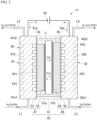
- FIG. 2 is a cross-sectional view schematically showing the electrolytic cell 11.
- the electrolytic cell 11 includes a first separator 41, a second separator 42, and a membrane electrode assembly 43.
- the first separator 41 is a member that defines one surface of an internal space S of the electrolytic cell 11.
- the internal space S is a space including the cathode chamber Sa and the anode chamber Sb described later.
- the first separator 41 has a rectangular plate shape and includes a metal member.
- a negative voltage is applied to the first separator 41 from the power supply unit 30 via a first current collector 61 (refer to FIG. 3 ) described later.
- the first separator 41 has a first end portion 41el (for example, a lower end portion) and a second end portion 41e2 (for example, an upper end portion) located on a side opposite to the first end portion 41e1.
- the above-described piping line L1 is connected to the first end portion 41e1 of the first separator 41.
- the above-described piping line L2 is connected to the second end portion 41e2 of the first separator 41.
- the first separator 41 has a first inner surface 41a that faces the cathode chamber Sa described later.
- a first flow path FP1 through which the electrolyte supplied from the piping line L1 flows is formed on the first inner surface 41a.
- the first flow path FP1 is a groove provided in the first inner surface 41a.
- the electrolyte that has flowed through the first flow path FP1 is discharged to the outside of the electrolytic cell 11 through the piping line L2.
- Each structure for example, a flow path structure
- FIG. 2 is merely an example and does not limit the content of the present embodiment.
- various structures can be used as the flow path structure depending on the size, purpose, and use environment of the device. The same applies to each structure shown in other drawings.
- the second separator 42 is a member that is disposed with an internal space S between the second separator 42 and at least part of the first separator 41 and that defines the other surface of the internal space S.
- the second separator 42 has a rectangular plate shape and includes a metal member.
- a positive voltage is applied to the second separator 42 from the power supply unit 30 via a second current collector 62 (refer to FIG. 3 ) described later.
- the first separator 41 and the second separator 42 included in the same electrolytic cell 11 form an electrolyzer 40 of the electrolytic cell 11 as a pair of separators.
- the second separator 42 has a first end portion 42e1 (for example, a lower end portion) and a second end portion 42e2 (for example, an upper end portion) located on a side opposite to the first end portion 42e1.
- the above-described piping line L3 is connected to the first end portion 42e1 of the second separator 42.
- the above-described piping line L4 is connected to the second end portion 42e2 of the second separator 42.
- the second separator 42 has a second inner surface 42a that faces the anode chamber Sb described later.
- a second flow path FP2 through which the electrolyte supplied from the piping line L3 flows is formed on the second inner surface 42a.
- the second flow path FP2 is a groove provided in the second inner surface 42a. The electrolyte that has flowed through the second flow path FP2 is discharged to the outside of the electrolytic cell 11 through the piping line L4.
- the first separator 41 of the electrolytic cell 11 included in the electrolytic cell stack 10 may be a bipolar plate having the same groove for a flow path (first flow path FP1, shown by a two-dot chain line in FIG. 2 ) on a surface 41b opposite to the first inner surface 41a in addition to the first inner surface 41a.
- the second separator 42 of the electrolytic cell 11 included in the electrolytic cell stack 10 may be a bipolar plate having the same groove for a flow path (second flow path FP2, shown by a two-dot chain line in FIG. 2 ) on a surface 42b opposite to the second inner surface 42a in addition to the second inner surface 42a.
- the grooves for flow paths provided on both surfaces of the first separator 41 may have different shapes and dispositions.
- the grooves for flow paths provided on both surfaces of the second separator 42 may have different shapes and dispositions.
- a membrane electrode assembly (MEA) 43 is a structure in which an ion exchange membrane, a catalyst, and a power supply body are assembled.
- the membrane electrode assembly 43 is disposed between the first separator 41 and the second separator 42 and is located in the internal space S.
- the membrane electrode assembly 43 includes an ion exchange membrane 51, a cathode catalyst layer 52, a cathode power supply body 53, an anode catalyst layer 54, and an anode power supply body 55.
- the ion exchange membrane 51 is a membrane that selectively allows ions to permeate.
- the ion exchange membrane 51 is a solid polymer electrolyte membrane.
- the ion exchange membrane 51 is an anion exchange membrane (AEM) having hydroxide ion conductivity.
- AEM anion exchange membrane
- the ion exchange membrane 51 is not limited to the above-described example and may be an ion exchange membrane having a type different from the above-described example.
- the ion exchange membrane 51 has a rectangular sheet shape.
- the external size of the ion exchange membrane 51 is smaller than the external size of the first separator 41 or the second separator 42.
- the ion exchange membrane 51 is disposed between the first separator 41 and the second separator 42 and is located in the above-described internal space S.
- the ion exchange membrane 51 has a first surface 51a facing the first inner surface 41a of the first separator 41 and a second surface 51b located on a side opposite to the first surface 51a and facing the second inner surface 42a of the second separator 42.
- the cathode chamber Sa is defined between the first surface 51a of the ion exchange membrane 51 and the first inner surface 41a of the first separator 41.
- the anode chamber Sb is defined between the second surface 51b of the ion exchange membrane 51 and the second inner surface 42a of the second separator 42.
- the cathode chamber Sa in a case where a voltage is applied to the electrolytic cell 11, the following chemical reaction occurs, and hydrogen is generated from the electrolyte.
- the phrase that "XX is generated” may also include a case where another substance is simultaneously generated in association with the generation of XX.
- the hydroxide ions generated in the cathode chamber Sa pass through the membrane electrode assembly 43 and move from the cathode chamber Sa to the anode chamber Sb. 2H 2 O + 2e - ⁇ H 2 + 2OH -
- the cathode catalyst layer 52 is a layer that accelerates the chemical reaction in the cathode chamber Sa described above.
- the cathode catalyst layer 52 has a rectangular sheet shape.
- the external size of the cathode catalyst layer 52 is smaller than the external size of the ion exchange membrane 51.
- the cathode catalyst layer 52 is disposed in the cathode chamber Sa and is adjacent to the ion exchange membrane 51.
- the term of "adjacent" is not limited to a case where two members are independently adjacent to each other and may also include a case where at least part of one member of the two members enters the other member.
- part of the cathode catalyst layer 52 may enter a surface portion of the ion exchange membrane 51.
- the cathode catalyst layer 52 is provided on the first surface 51a of the ion exchange membrane 51.
- the cathode catalyst layer 52 is formed by applying a material of the cathode catalyst layer 52 to the first surface 51a of the ion exchange membrane 51.
- a negative voltage is applied to the cathode catalyst layer 52 from the power supply unit 30 via the first separator 41 and the cathode power supply body 53, and the cathode catalyst layer 52 functions as part of the cathode 47 of the electrolytic cell 11.
- the cathode catalyst layer 52 As a material of the cathode catalyst layer 52, any material that accelerates the chemical reaction in the cathode chamber Sa described above may be used, and various materials can be used.
- the cathode catalyst layer 52 contains one or more nickel, a nickel alloy, a cerium oxide, a lanthanum oxide, or platinum.
- the term of "XX oxide” may contain another material other than XX and oxygen.
- the cathode catalyst layer 52 may include another material such as carbon in addition to the above-described material. "XX" is any material.
- the cathode power supply body 53 is an electrical connection portion that transmits a voltage applied to the first separator 41 to the cathode catalyst layer 52.
- the cathode power supply body 53 is disposed in the cathode chamber Sa.
- the cathode power supply body 53 is located between the first inner surface 41a of the first separator 41 and the cathode catalyst layer 52 and is in contact with each of the first inner surface 41a of the first separator 41 and the cathode catalyst layer 52. At least part of the cathode power supply body 53 may overlap at least part of at least one of the first separator 41 or the cathode catalyst layer 52.
- the cathode power supply body 53 has a structure in which an electrolyte and gas can pass through the inside.
- the cathode power supply body 53 is made of a metal mesh structure, a sintered body, a fiber, or the like.
- the external size of the cathode power supply body 53 is the same as the external size of the cathode catalyst layer 52.
- the cathode 47 of the electrolytic cell 11 includes the cathode catalyst layer 52 and the cathode power supply body 53.
- the anode catalyst layer 54 is a layer that accelerates the chemical reaction in the anode chamber Sb described above.
- the anode catalyst layer 54 has a rectangular sheet shape.
- the external size of the anode catalyst layer 54 is smaller than the external size of the ion exchange membrane 51.
- the anode catalyst layer 54 is disposed in the anode chamber Sb and is adjacent to the ion exchange membrane 51. For example, part of the anode catalyst layer 54 may enter the surface portion of the ion exchange membrane 51.
- the anode catalyst layer 54 is provided on the second surface 51b of the ion exchange membrane 51.
- the anode catalyst layer 54 is formed by applying a material of the anode catalyst layer 54 to the second surface 51b of the ion exchange membrane 51.
- a positive voltage is applied to the anode catalyst layer 54 from the power supply unit 30 via the second separator 42 and the anode power supply body 55, and the anode catalyst layer 54 functions as part of the anode 48 of the electrolytic cell 11.
- the anode catalyst layer 54 As a material of the anode catalyst layer 54, any material that accelerates the chemical reaction in the above-described anode chamber Sb may be used, and various materials can be used.
- the anode catalyst layer 54 contains one or more nickel, a nickel alloy, a nickel oxide, a copper oxide, an iridium oxide, a niobium oxide, a lead oxide, or a bismuth oxide.
- the term of "XX oxide” in the present disclosure may contain another material other than XX and oxygen.
- nickel oxide may contain another material such as iron or cobalt in addition to nickel and oxygen.
- the term of "copper oxide” may contain another material such as cobalt in addition to copper and oxygen.
- iridium oxide may contain another material such as ruthenium in addition to iridium and oxygen.
- lead oxide may contain another material such as ruthenium in addition to lead and oxygen.
- bismuth oxide may contain another material such as ruthenium, in addition to bismuth and oxygen.
- the anode power supply body 55 is an electrical connection portion that transmits the voltage applied to the second separator 42 to the anode catalyst layer 54.
- the anode power supply body 55 is disposed in the anode chamber Sb.
- the anode power supply body 55 is located between the second inner surface 42a of the second separator 42 and the anode catalyst layer 54 and is in contact with each of the second inner surface 42a of the second separator 42 and the anode catalyst layer 54. At least part of the anode power supply body 55 may overlap at least part of at least one of the second separator 42 or the anode catalyst layer 54.
- the anode power supply body 55 has a structure in which an electrolyte and gas can pass through the inside.
- the anode power supply body 55 is made of a metal mesh structure, a sintered body, a fiber, or the like.
- the external size of the anode power supply body 55 is the same as the external size of the anode catalyst layer 54.
- the anode 48 of the electrolytic cell 11 includes the anode catalyst layer 54 and the anode power supply body 55.
- FIG. 3 is an exploded perspective view showing the electrolytic cell 11.
- the electrolytic cell 11 includes the first current collector 61, the second current collector 62, a first insulator 63, a second insulator 64, a first insulating material 65, a second insulating material 66, a first end plate 67, and a second end plate 68, in addition to the above-described configuration.
- a support portion 70 and a sealing portion 80 described later are not shown.
- the first current collector 61 is a metal plate member (for example, a copper plate).
- the first current collector 61 is in contact with the first separator 41 from a side of the electrolytic cell 11 opposite to the internal space S and is electrically connected to the first separator 41.
- a negative voltage desired for the electrolysis in the electrolytic cell 11 is applied to the first current collector 61 from the power supply unit 30.
- the first current collector 61 may be shared by two electrolytic cells 11 adjacent to each other in the electrolytic cell stack 10.
- the second current collector 62 is an electrical connection portion that transmits the positive voltage applied from the power supply unit 30 to the second separator 42.
- the second current collector 62 is a metal plate member (for example, a copper plate).
- the second current collector 62 is in contact with the second separator 42 from a side of the electrolytic cell 11 opposite to the internal space S and is electrically connected to the second separator 42.
- a positive voltage desired for the electrolysis in the electrolytic cell 11 is applied to the second current collector 62 from the power supply unit 30.
- the second current collector 62 may be shared by two electrolytic cells 11 adjacent to each other in the electrolytic cell stack 10.
- the first insulator 63 is a member that insulates an outer peripheral portion of the first separator 41 and an outer peripheral portion of the second separator 42.
- the first insulator 63 is a frame-shaped sheet member that is larger than the outer shape of the cathode catalyst layer 52 and the outer shape of the cathode power supply body 53 by one size.
- the first insulator 63 is attached to the first inner surface 41a of the first separator 41 and covers an end portion of the first inner surface 41a.
- the material of the first insulator 63 is not particularly limited as long as the material is an insulating material, and is, for example, a sheet-like resin such as polytetrafluoroethylene (PTFE).
- the second insulator 64 is a member that insulates the outer peripheral portion of the first separator 41 and the outer peripheral portion of the second separator 42, similarly to the first insulator 63.
- the second insulator 64 is a frame-shaped sheet member that is larger than the outer shape of the anode catalyst layer 54 and the outer shape of the anode power supply body 55 by one size.
- the second insulator 64 is attached to the second inner surface 42a of the second separator 42 and covers an end portion of the second inner surface 42a.
- the material of the second insulator 64 is not particularly limited as long as the material is an insulating material and is, for example, a sheet-like resin such as PTFE.
- the first insulator 63 and the second insulator 64 can also be used as an integrated insulator.
- the first insulating material 65 is located between the first current collector 61 and the first end plate 67.
- the external size of the first insulating material 65 is the same as the external size of the first current collector 61 or larger than the external size of the first current collector 61.
- the second insulating material 66 is located between the second current collector 62 and the second end plate 68.
- the external size of the second insulating material 66 is the same as the external size of the second current collector 62 or larger than the external size of the second current collector 62.
- the first end plate 67 is located on a side opposite to the first insulating material 65 with respect to the internal space S of the electrolytic cell 11.
- the external size of the first end plate 67 is larger than the external size of the first insulating material 65.
- the second end plate 68 is located on a side opposite to the second insulating material 66 with respect to the internal space S of the electrolytic cell 11.
- the external size of the second end plate 68 is larger than the external size of the second insulating material 66.
- the electrolytic cell 11 is not limited to the above-described configuration.
- two adjacent electrolytic cells 11 among the plurality of electrolytic cells 11 may share the first separator 41 or the second separator 42, each of which is a bipolar plate.
- the current collector (the first current collector 61 or the second current collector 62), the insulator (the first insulator 63 or the second insulator 64), the insulating material (the first insulating material 65 or the second insulating material 66), and the end plate (the first end plate 67 or the second end plate 68) may not be present between the two adjacent electrolytic cells 11.
- FIG. 4 is a cross-sectional view showing the electrolytic cell 11.
- the external size of the ion exchange membrane 51 is larger than each of the external size of the cathode catalyst layer 52 and the external size of the cathode power supply body 53.
- the area of the ion exchange membrane 51 is larger than each of the area of the cathode catalyst layer 52 and the area of the cathode power supply body 53.
- the ion exchange membrane 51 protrudes outside (on the outer peripheral side) the cathode catalyst layer 52 and the cathode power supply body 53 in a direction (for example, the X direction or the Y direction) orthogonal to the thickness direction (Z direction) of the membrane electrode assembly 43.
- the term of "outside” or “outer peripheral side” means a side away from the central portion C of the ion exchange membrane 51 in a direction (for example, the X direction or the Y direction) orthogonal to the thickness direction (Z direction) of the membrane electrode assembly 43.
- the external size of the ion exchange membrane 51 is larger than each of the external size of the anode catalyst layer 54 and the external size of the anode power supply body 55.
- the area of the ion exchange membrane 51 is larger than each of the area of the anode catalyst layer 54 and the area of the anode power supply body 55.
- the ion exchange membrane 51 protrudes on the outer peripheral side of the anode catalyst layer 54 and the anode power supply body 55 in a direction (for example, the X direction or the Y direction) orthogonal to the thickness direction (Z direction) of the membrane electrode assembly 43.
- the electrolytic cell 11 includes a support portion 70 and a sealing portion 80.
- the support portion 70 is a member that supports the membrane electrode assembly 43 inside the electrolytic cell 11.
- the sealing portion 80 is a member that closes the internal space S between the first separator 41 and the second separator 42.
- the support portion 70 is disposed between the first separator 41 and the second separator 42.
- the support portion 70 is located inside (on the inner peripheral side) an outer edge portion 51e of the ion exchange membrane 51 and supports the ion exchange membrane 51.
- the term of "outer edge portion” means an edge portion that is separated from the central portion C of the ion exchange membrane 51 in a direction (for example, the X direction or the Y direction) orthogonal to the thickness direction (Z direction) of the membrane electrode assembly 43.
- the term of "inside” or “inner peripheral side” means an inside (a side close to the central portion C) as viewed from the central portion C of the ion exchange membrane 51.
- the support portion 70 includes a first support portion 71 and a second support portion 72.
- the first support portion 71 is a support portion on the cathode side.
- the first support portion 71 is disposed between the first inner surface 41a of the first separator 41 and the first surface 51a of the ion exchange membrane 51.
- the first support portion 71 is located inside (on the inner peripheral side) the outer edge portion 51e of the ion exchange membrane 51.
- the first support portion 71 is sandwiched between the first inner surface 41a (or the first insulator 63) of the first separator 41 and the first surface 51a of the ion exchange membrane 51 at a position outside (on the outer peripheral side) the cathode catalyst layer 52 and the cathode power supply body 53 and supports the ion exchange membrane 51 with respect to the first inner surface 41a of the first separator 41.
- the first support portion 71 is formed in an annular shape (for example, a frame shape) along the outer edge portion 51e of the ion exchange membrane 51, and in an annular shape that is smaller than the outer edge portion 51e of the ion exchange membrane 51 by one size.
- the second support portion 72 is a support portion on the anode side.
- the second support portion 72 is disposed between the second inner surface 42a of the second separator 42 and the second surface 51b of the ion exchange membrane 51.
- the second support portion 72 is located inside (on the inner peripheral side) the outer edge portion 51e of the ion exchange membrane 51.
- the second support portion 72 is sandwiched between the second inner surface 42a of the second separator 42 and the second surface 51b of the ion exchange membrane 51 at a position outside (on the outer peripheral side) the anode catalyst layer 54 and the anode power supply body 55 and supports the ion exchange membrane 51 with respect to the second inner surface 42a of the second separator 42.
- the second support portion 72 is formed in an annular shape (for example, a frame shape) along the outer edge portion 51e of the ion exchange membrane 51, and in an annular shape that is smaller than the outer edge portion 52e of the ion exchange membrane 51 by one size.
- the sealing portion 80 is disposed between the first separator 41 and the second separator 42.
- the sealing portion 80 is located outside (on the outer peripheral side) the outer edge portion 51e of the ion exchange membrane 51 and seals the internal space S of the electrolytic cell 11.
- the sealing portion 80 includes a first sealing portion 81 and a second sealing portion 82.
- the first sealing portion 81 and the second sealing portion 82 may be formed integrally. That is, the first sealing portion 81 and the second sealing portion 82 may be one member.
- the sealing portion 80 may be formed integrally with at least one of the first insulator 63 and the second insulator 64 described above.
- the first sealing portion 81 is a sealing portion on the cathode side.
- the first sealing portion 81 is located outside (on the outer peripheral side) the outer edge portion 51e of the ion exchange membrane 51.
- the first sealing portion 81 is sandwiched between the first inner surface 41a of the first separator 41 and the second sealing portion 82 and seals part of the outer peripheral side of the internal space S.
- the first sealing portion 81 is formed in an annular shape (for example, a frame shape) along the outer edge portion 51e of the ion exchange membrane 51, and in an annular shape that is larger than the outer edge portion 51e of the ion exchange membrane 51 by one size.
- the second sealing portion 82 is a sealing portion on the anode side.
- the second sealing portion 82 is located outside the outer edge portion 51e of the ion exchange membrane 51.
- the second sealing portion 82 is sandwiched between the second inner surface 42a of the second separator 42 and the first sealing portion 81 and seals part of the outer peripheral side of the internal space S.
- the second sealing portion 82 is formed in an annular shape (for example, a frame shape) along the outer edge portion 51e of the ion exchange membrane 51, and in an annular shape that is larger than the outer edge portion 51e of the ion exchange membrane 51 by one size.
- the area ratio of the cathode and the anode will be described.
- the area of the anode 48 is larger than the area of the cathode 47.
- the area of the anode catalyst layer 54 is larger than the area of the cathode catalyst layer 52.
- the area of the anode power supply body 55 is larger than the area of the cathode power supply body 53.
- the area ratio of the anode 48 to the cathode 47 is more than 1.0 and 2.0 or less.
- the area ratio of the anode 48 to the cathode 47 is set such that a rate of increase in the overvoltage of the anode 48 due to the progress of deterioration is less than 2 times (more preferably less than 1.5 times) as compared with a rate of increase in the overvoltage of the cathode 47.
- FIG. 5 is a graph describing the action of the electrolytic cell 11.
- FIG. 5 is a graph showing test results of the current-voltage characteristics in the electrolytic cell of the comparative example in which the area of the anode and the area of the cathode are the same.
- the term of "cycle" means a predetermined period set in advance. As shown in FIG. 5 , it is found that the overvoltage increases as the number of cycles increases (that is, as the use time increases) in the electrolytic cell of the comparative example.
- FIG. 6 is another graph describing the action of the electrolytic cell 11.
- FIG. 6 is a graph showing the test results of a relationship between the number of cycles and the reaction resistance in the electrode in the above comparative example.
- the reaction resistance in the anode 48 has an absolute value larger than the reaction resistance in the cathode 47.
- a rate of increase in the reaction resistance in the anode 48 due to the progress of deterioration is larger than a rate of increase in the reaction resistance in the cathode 47 due to the progress of deterioration.
- the rate of increase in reaction resistance in the anode 48 is 2 times or more as compared with the rate of increase in reaction resistance in the cathode 47. This is because an oxidation reaction occurs at the anode 48, and the deterioration of the anode 48 is larger than the deterioration of the cathode 47.
- the area of the anode 48 is formed larger than the area of the cathode 47. According to such a configuration, the oxidation reaction in the anode 48 can be dispersed over a wide area of the anode 48. As a result, it is possible to suppress the deterioration of the anode 48 from being larger than that of the cathode 47, as compared with the comparative example. When it is possible to suppress the deterioration of the anode 48 from being larger than that of the cathode 47, it is possible to suppress an increase in the overvoltage and to improve the performance and the life of the electrolytic cell 11A.
- the current is likely to flow around at an end portion of the catalyst layer, and the current density is likely to increase at the end portion of the catalyst layer. Therefore, in a case where the areas of the cathode catalyst layer and the anode catalyst layer are the same as in the comparative example, since the end portions of the catalyst layers having a high current density face each other, local deterioration is likely to increase at the end portion of each catalyst layer.
- the anode catalyst layer 54 is larger than the cathode catalyst layer 52, the end portions of each catalyst layer having a high current density are shifted from each other. As a result, the deterioration is unlikely to increase at the end portion of each catalyst layer. From this viewpoint as well, it is possible to suppress an increase in the overvoltage and to improve the performance and the life of the electrolytic cell 11.
- the rate of increase in the reaction resistance in the anode 48 is 2 times or more as compared with the rate of increase in the reaction resistance in the cathode 47.
- the area ratio of the anode 48 to the cathode 47 is set based on the rate of increase in reaction resistance in the anode 48 and the rate of increase in reaction resistance in the cathode 47.
- the area ratio of the anode 48 to the cathode 47 is adjusted and determined such that a difference between the rate of increase in the reaction resistance of the anode 48 and the rate of increase in the reaction resistance of the cathode 47 is equal to or less than a predetermined standard (for example, less than 2 times, and more preferably less than 1.5 times).
- the catalyst carrying amount of the anode catalyst layer 54 is 1 times or more as compared with the catalyst carrying amount of the cathode catalyst layer 52.
- the term of "catalyst carrying amount” means the weight of the catalyst per unit area [mg/cm 2 ].
- the second embodiment is different from the first embodiment in that the thickness of the anode catalyst layer 54 is larger than the thickness of the cathode catalyst layer 52.
- FIG. 7 is a cross-sectional view showing an electrolytic cell 11A of a second embodiment.
- the area of the anode catalyst layer 54 is larger than the area of the cathode catalyst layer 52, and the thickness of the anode catalyst layer 54 is thicker than the thickness of the cathode catalyst layer 52.
- the catalyst carrying amount of the anode catalyst layer 54 is 1 times or more as compared with the catalyst carrying amount of the cathode catalyst layer 52.
- the volume ratio (or the catalyst carrying amount ratio) of the anode catalyst layer 54 to the cathode catalyst layer 52 is set such that the rate of increase in the overvoltage of the anode 48 due to the progress of deterioration is less than 2 times (more preferably less than 1.5 times) as compared with the rate of increase in the overvoltage of the cathode 47.
- the volume ratio of the anode 48 to the cathode 47 is adjusted and determined such that a difference between the rate of increase in the reaction resistance of the anode 48 and the rate of increase in the reaction resistance of the cathode 47 is equal to or less than a predetermined standard (for example, less than 2 times, and more preferably less than 1.5 times).
- electrolytic cells 11 and 11A and the electrolysis device 1 described in each embodiment are grasped as follows, for example.
- deterioration progresses according to the time when a direct current voltage is applied, but deterioration progresses faster in the anode than in the cathode.
- the progress of deterioration causes an increase in resistance value and is manifested as an increase in voltage in a case where the current density is kept constant.
- a plurality of specimens of electrolytic cells having different area ratios of the anode to the cathode were produced, and evaluation experiments were performed to examine the increase in voltage of the anode in the electrolytic cell after a predetermined time had elapsed.
- specimen A in which the area of the anode and the area of the cathode were equal was produced. Furthermore, as the electrolytic cell of the present disclosure, specimens B, C, and D in which the area of the anode 48 was larger than the area of the cathode 47 were produced.
- the dimensions of the anode and the cathode and the area ratio of the anode to the cathode in the specimens A, B, C, and D are as follows.
- the dimensions of the anode and the cathode in the specimen A are both 45 mm in height ⁇ 45 mm in width, and thus the area ratio of the anode to the cathode in the specimen A is 1.
- all the specimens B, C, and D have the same size, the dimensions of the anode are 50 mm in height ⁇ 50 mm in width, the dimensions of the cathode are 41 mm in height ⁇ 41 mm in width, and thus the area ratio of the anode to the cathode of the specimens B, C, and D is 1.5.
- the catalyst carrying amount ratio is also 1.5.
- the specimens A, B, C, and D were individually installed at the positions of the electrolytic cell 11, and the energization test was performed four times.
- the power supply unit 30 was driven, a direct current voltage was applied between the anode 48 and the cathode 47 of the electrolytic cell 11 such that the current density was constant (2 amperes/cm 2 ), and the increases in voltage of the anode 48 in a period from 100 hours after the start of the voltage application to 400 hours after the start of the voltage application were examined.
- FIG. 8 shows evaluation values of the increase in voltage of the anode 48 in the specimens B, C, and D after the above test period has elapsed.
- the increase in voltage (the difference in voltage value) of the specimen A to be compared was set to 100
- the increase in voltage of the specimen B with respect to the increase in voltage of the specimen A was 63
- the increase in voltage of the specimen C with respect to the increase in voltage of the specimen A was 88
- the increase in voltage of the specimen D with respect to the increase in voltage of the specimen A was 25.
- the present disclosure relates to an electrolytic cell and an electrolysis device in which the progress of deterioration is slow and a performance deterioration is unlikely to occur.
Landscapes
- Chemical & Material Sciences (AREA)
- Engineering & Computer Science (AREA)
- Chemical Kinetics & Catalysis (AREA)
- Electrochemistry (AREA)
- Materials Engineering (AREA)
- Metallurgy (AREA)
- Organic Chemistry (AREA)
- Inorganic Chemistry (AREA)
- Electrolytic Production Of Non-Metals, Compounds, Apparatuses Therefor (AREA)
Applications Claiming Priority (2)
| Application Number | Priority Date | Filing Date | Title |
|---|---|---|---|
| JP2022090936 | 2022-06-03 | ||
| PCT/JP2023/020234 WO2023234335A1 (fr) | 2022-06-03 | 2023-05-31 | Cellule d'électrolytique et électrolyseur |
Publications (2)
| Publication Number | Publication Date |
|---|---|
| EP4516968A1 true EP4516968A1 (fr) | 2025-03-05 |
| EP4516968A4 EP4516968A4 (fr) | 2026-02-18 |
Family
ID=89024870
Family Applications (1)
| Application Number | Title | Priority Date | Filing Date |
|---|---|---|---|
| EP23816092.3A Pending EP4516968A4 (fr) | 2022-06-03 | 2023-05-31 | Cellule d'électrolytique et électrolyseur |
Country Status (6)
| Country | Link |
|---|---|
| US (1) | US20250327196A1 (fr) |
| EP (1) | EP4516968A4 (fr) |
| JP (1) | JPWO2023234335A1 (fr) |
| AU (1) | AU2023278646B2 (fr) |
| TW (1) | TWI864791B (fr) |
| WO (1) | WO2023234335A1 (fr) |
Families Citing this family (1)
| Publication number | Priority date | Publication date | Assignee | Title |
|---|---|---|---|---|
| CN118147669B (zh) * | 2024-02-09 | 2025-12-02 | 国能科技成果转化(北京)有限公司 | 一种非对称式电解槽 |
Family Cites Families (9)
| Publication number | Priority date | Publication date | Assignee | Title |
|---|---|---|---|---|
| JP5622544B2 (ja) * | 2010-12-03 | 2014-11-12 | 高砂熱学工業株式会社 | 水素製造セル及び水素製造装置 |
| JP6288473B2 (ja) * | 2015-10-20 | 2018-03-07 | 三菱重工環境・化学エンジニアリング株式会社 | 水素発生装置 |
| JP2018076576A (ja) * | 2016-11-11 | 2018-05-17 | 学校法人 工学院大学 | 水電解用触媒電極、水電解装置、水電解用触媒電極の製造方法 |
| KR102923430B1 (ko) * | 2017-12-05 | 2026-02-06 | 가부시끼가이샤 도꾸야마 | 알칼리수 전해용 막-전극-개스킷 복합체 |
| JP7543001B2 (ja) * | 2020-06-15 | 2024-09-02 | 旭化成株式会社 | アルカリ水電解槽 |
| JP7104110B2 (ja) * | 2020-08-06 | 2022-07-20 | 本田技研工業株式会社 | 水電解システム |
| JP7593004B2 (ja) * | 2020-08-06 | 2024-12-03 | オムロン株式会社 | 表示システム、表示方法、及び表示プログラム |
| JP7108010B2 (ja) * | 2020-11-24 | 2022-07-27 | 本田技研工業株式会社 | 水素・酸素製造システムの制御方法および水素・酸素製造システム |
| JP7550628B2 (ja) | 2020-12-08 | 2024-09-13 | トヨタホーム株式会社 | 電力供給システム |
-
2023
- 2023-05-31 JP JP2024524899A patent/JPWO2023234335A1/ja active Pending
- 2023-05-31 US US18/870,875 patent/US20250327196A1/en active Pending
- 2023-05-31 EP EP23816092.3A patent/EP4516968A4/fr active Pending
- 2023-05-31 AU AU2023278646A patent/AU2023278646B2/en active Active
- 2023-05-31 WO PCT/JP2023/020234 patent/WO2023234335A1/fr not_active Ceased
- 2023-06-01 TW TW112120548A patent/TWI864791B/zh active
Also Published As
| Publication number | Publication date |
|---|---|
| US20250327196A1 (en) | 2025-10-23 |
| TWI864791B (zh) | 2024-12-01 |
| AU2023278646B2 (en) | 2026-03-12 |
| JPWO2023234335A1 (fr) | 2023-12-07 |
| EP4516968A4 (fr) | 2026-02-18 |
| TW202407153A (zh) | 2024-02-16 |
| AU2023278646A1 (en) | 2024-12-19 |
| WO2023234335A1 (fr) | 2023-12-07 |
Similar Documents
| Publication | Publication Date | Title |
|---|---|---|
| US6855450B2 (en) | Proton exchange membrane electrochemical cell system | |
| EP4516967A1 (fr) | Assemblage électrode-membrane, cellule d'électrolyse, dispositif d'électrolyse et procédé de production d'assemblage électrode-membrane | |
| US7951284B2 (en) | Electrolysis apparatus, electrochemical reaction membrane apparatus, porous electrical conductor, and production method thereof | |
| EP4516968A1 (fr) | Cellule d'électrolytique et électrolyseur | |
| KR20140133301A (ko) | 전기화학셀용 막전극 접합체 | |
| US12448692B2 (en) | Method for fastening an electrode | |
| EP4610403A1 (fr) | Assemblage membrane-électrodes et procédé de fabrication d'assemblage membrane-électrodes | |
| EP4624631A1 (fr) | Cellule d'électrolyse et appareil d'électrolyse | |
| EP4640923A1 (fr) | Dispositif d'électrolyse | |
| EP4640924A1 (fr) | Cellule électrochimique et dispositif électrolytique | |
| EP4632113A1 (fr) | Cellule électrolytique et appareil électrolytique | |
| EP4534729A2 (fr) | Structure d'électrode | |
| TWI920895B (zh) | 電解單元及電解裝置 | |
| EP4442861A1 (fr) | Structure d'électrode et électrolyseur d'eau | |
| JP7661445B1 (ja) | セパレータ、及び電解装置 | |
| EP4534731A2 (fr) | Structure d'électrode | |
| JP7661548B1 (ja) | 電解セル、及び電解装置 | |
| TWI922858B (zh) | 電解單元及電解裝置 | |
| EP4442862A1 (fr) | Ensemble de plaque d'extrémité avec insert isolant le fluide pour une empilement pour électrolyseur, et système électrolyseur correspondant | |
| EP4435146A2 (fr) | Structure d'électrode et électrolyseur d'eau | |
| EP4534730A2 (fr) | Structure d'électrode | |
| US10608307B2 (en) | Anaerobic aluminum-water electrochemical cell | |
| JP2025151930A (ja) | 電解セル、及び電解装置 | |
| WO2025169572A1 (fr) | Cellule d'électrolyse et dispositif d'électrolyse | |
| JP2010009761A (ja) | 固体高分子型燃料電池 |
Legal Events
| Date | Code | Title | Description |
|---|---|---|---|
| STAA | Information on the status of an ep patent application or granted ep patent |
Free format text: STATUS: THE INTERNATIONAL PUBLICATION HAS BEEN MADE |
|
| PUAI | Public reference made under article 153(3) epc to a published international application that has entered the european phase |
Free format text: ORIGINAL CODE: 0009012 |
|
| STAA | Information on the status of an ep patent application or granted ep patent |
Free format text: STATUS: REQUEST FOR EXAMINATION WAS MADE |
|
| 17P | Request for examination filed |
Effective date: 20241129 |
|
| AK | Designated contracting states |
Kind code of ref document: A1 Designated state(s): AL AT BE BG CH CY CZ DE DK EE ES FI FR GB GR HR HU IE IS IT LI LT LU LV MC ME MK MT NL NO PL PT RO RS SE SI SK SM TR |
|
| DAV | Request for validation of the european patent (deleted) | ||
| DAX | Request for extension of the european patent (deleted) | ||
| A4 | Supplementary search report drawn up and despatched |
Effective date: 20260120 |
|
| RIC1 | Information provided on ipc code assigned before grant |
Ipc: C25B 9/23 20210101AFI20260114BHEP Ipc: C25B 1/04 20210101ALI20260114BHEP Ipc: C25B 9/00 20210101ALI20260114BHEP Ipc: C25B 9/60 20210101ALI20260114BHEP Ipc: C25B 9/65 20210101ALI20260114BHEP Ipc: C25B 9/75 20210101ALI20260114BHEP Ipc: C25B 9/77 20210101ALI20260114BHEP |