EP4516967A1 - Assemblage électrode-membrane, cellule d'électrolyse, dispositif d'électrolyse et procédé de production d'assemblage électrode-membrane - Google Patents
Assemblage électrode-membrane, cellule d'électrolyse, dispositif d'électrolyse et procédé de production d'assemblage électrode-membrane Download PDFInfo
- Publication number
- EP4516967A1 EP4516967A1 EP23815503.0A EP23815503A EP4516967A1 EP 4516967 A1 EP4516967 A1 EP 4516967A1 EP 23815503 A EP23815503 A EP 23815503A EP 4516967 A1 EP4516967 A1 EP 4516967A1
- Authority
- EP
- European Patent Office
- Prior art keywords
- ion exchange
- exchange membrane
- catalyst layer
- electrode assembly
- membrane
- Prior art date
- Legal status (The legal status is an assumption and is not a legal conclusion. Google has not performed a legal analysis and makes no representation as to the accuracy of the status listed.)
- Pending
Links
Images


Classifications
-
- C—CHEMISTRY; METALLURGY
- C25—ELECTROLYTIC OR ELECTROPHORETIC PROCESSES; APPARATUS THEREFOR
- C25B—ELECTROLYTIC OR ELECTROPHORETIC PROCESSES FOR THE PRODUCTION OF COMPOUNDS OR NON-METALS; APPARATUS THEREFOR
- C25B9/00—Cells or assemblies of cells; Constructional parts of cells; Assemblies of constructional parts, e.g. electrode-diaphragm assemblies; Process-related cell features
- C25B9/70—Assemblies comprising two or more cells
- C25B9/73—Assemblies comprising two or more cells of the filter-press type
- C25B9/75—Assemblies comprising two or more cells of the filter-press type having bipolar electrodes
-
- C—CHEMISTRY; METALLURGY
- C25—ELECTROLYTIC OR ELECTROPHORETIC PROCESSES; APPARATUS THEREFOR
- C25B—ELECTROLYTIC OR ELECTROPHORETIC PROCESSES FOR THE PRODUCTION OF COMPOUNDS OR NON-METALS; APPARATUS THEREFOR
- C25B13/00—Diaphragms; Spacing elements
- C25B13/02—Diaphragms; Spacing elements characterised by shape or form
-
- C—CHEMISTRY; METALLURGY
- C25—ELECTROLYTIC OR ELECTROPHORETIC PROCESSES; APPARATUS THEREFOR
- C25B—ELECTROLYTIC OR ELECTROPHORETIC PROCESSES FOR THE PRODUCTION OF COMPOUNDS OR NON-METALS; APPARATUS THEREFOR
- C25B13/00—Diaphragms; Spacing elements
- C25B13/04—Diaphragms; Spacing elements characterised by the material
- C25B13/08—Diaphragms; Spacing elements characterised by the material based on organic materials
-
- C—CHEMISTRY; METALLURGY
- C25—ELECTROLYTIC OR ELECTROPHORETIC PROCESSES; APPARATUS THEREFOR
- C25B—ELECTROLYTIC OR ELECTROPHORETIC PROCESSES FOR THE PRODUCTION OF COMPOUNDS OR NON-METALS; APPARATUS THEREFOR
- C25B9/00—Cells or assemblies of cells; Constructional parts of cells; Assemblies of constructional parts, e.g. electrode-diaphragm assemblies; Process-related cell features
- C25B9/70—Assemblies comprising two or more cells
- C25B9/73—Assemblies comprising two or more cells of the filter-press type
- C25B9/77—Assemblies comprising two or more cells of the filter-press type having diaphragms
-
- C—CHEMISTRY; METALLURGY
- C25—ELECTROLYTIC OR ELECTROPHORETIC PROCESSES; APPARATUS THEREFOR
- C25B—ELECTROLYTIC OR ELECTROPHORETIC PROCESSES FOR THE PRODUCTION OF COMPOUNDS OR NON-METALS; APPARATUS THEREFOR
- C25B11/00—Electrodes; Manufacture thereof not otherwise provided for
- C25B11/04—Electrodes; Manufacture thereof not otherwise provided for characterised by the material
- C25B11/051—Electrodes formed of electrocatalysts on a substrate or carrier
- C25B11/073—Electrodes formed of electrocatalysts on a substrate or carrier characterised by the electrocatalyst material
- C25B11/075—Electrodes formed of electrocatalysts on a substrate or carrier characterised by the electrocatalyst material consisting of a single catalytic element or catalytic compound
- C25B11/077—Electrodes formed of electrocatalysts on a substrate or carrier characterised by the electrocatalyst material consisting of a single catalytic element or catalytic compound the compound being a non-noble metal oxide
-
- C—CHEMISTRY; METALLURGY
- C25—ELECTROLYTIC OR ELECTROPHORETIC PROCESSES; APPARATUS THEREFOR
- C25B—ELECTROLYTIC OR ELECTROPHORETIC PROCESSES FOR THE PRODUCTION OF COMPOUNDS OR NON-METALS; APPARATUS THEREFOR
- C25B11/00—Electrodes; Manufacture thereof not otherwise provided for
- C25B11/04—Electrodes; Manufacture thereof not otherwise provided for characterised by the material
- C25B11/051—Electrodes formed of electrocatalysts on a substrate or carrier
- C25B11/073—Electrodes formed of electrocatalysts on a substrate or carrier characterised by the electrocatalyst material
- C25B11/075—Electrodes formed of electrocatalysts on a substrate or carrier characterised by the electrocatalyst material consisting of a single catalytic element or catalytic compound
- C25B11/081—Electrodes formed of electrocatalysts on a substrate or carrier characterised by the electrocatalyst material consisting of a single catalytic element or catalytic compound the element being a noble metal
-
- C—CHEMISTRY; METALLURGY
- C25—ELECTROLYTIC OR ELECTROPHORETIC PROCESSES; APPARATUS THEREFOR
- C25B—ELECTROLYTIC OR ELECTROPHORETIC PROCESSES FOR THE PRODUCTION OF COMPOUNDS OR NON-METALS; APPARATUS THEREFOR
- C25B11/00—Electrodes; Manufacture thereof not otherwise provided for
- C25B11/04—Electrodes; Manufacture thereof not otherwise provided for characterised by the material
- C25B11/051—Electrodes formed of electrocatalysts on a substrate or carrier
- C25B11/073—Electrodes formed of electrocatalysts on a substrate or carrier characterised by the electrocatalyst material
- C25B11/075—Electrodes formed of electrocatalysts on a substrate or carrier characterised by the electrocatalyst material consisting of a single catalytic element or catalytic compound
- C25B11/089—Alloys
-
- Y—GENERAL TAGGING OF NEW TECHNOLOGICAL DEVELOPMENTS; GENERAL TAGGING OF CROSS-SECTIONAL TECHNOLOGIES SPANNING OVER SEVERAL SECTIONS OF THE IPC; TECHNICAL SUBJECTS COVERED BY FORMER USPC CROSS-REFERENCE ART COLLECTIONS [XRACs] AND DIGESTS
- Y02—TECHNOLOGIES OR APPLICATIONS FOR MITIGATION OR ADAPTATION AGAINST CLIMATE CHANGE
- Y02E—REDUCTION OF GREENHOUSE GAS [GHG] EMISSIONS, RELATED TO ENERGY GENERATION, TRANSMISSION OR DISTRIBUTION
- Y02E60/00—Enabling technologies; Technologies with a potential or indirect contribution to GHG emissions mitigation
- Y02E60/30—Hydrogen technology
- Y02E60/50—Fuel cells
Definitions
- the present disclosure relates to a membrane electrode assembly, an electrolytic cell, an electrolysis device, and a method of manufacturing the membrane electrode assembly.
- Patent Document 1 discloses a laminated electrolyte membrane including a first electrolyte membrane, a second electrolyte membrane, a nanosheet laminated catalyst layer provided between the first electrolyte membrane and the second electrolyte membrane and having a catalyst and a void, and a transfer layer provided between the second electrolyte membrane and the nanosheet laminated catalyst layer, as a laminated electrolyte membrane used in polymer electrolyte membrane (PEM)-type water electrolysis.
- PEM polymer electrolyte membrane
- a first electrode including a cathode catalyst layer and a second electrode including an anode catalyst layer are bonded to the laminated electrolyte membrane after the first electrolyte membrane, the second electrolyte membrane, the nanosheet laminated catalyst layer, and the transfer layer are integrated as the laminated electrolyte membrane.
- Patent Document 2 discloses a method of manufacturing an electrode, in which a support film and an EPTFE film are overlapped and passed between two metal rolls, a mixed liquid is supplied to impregnate a void in the EPTFE film with the mixed liquid, and then the support film is removed to obtain an electrode.
- an uneven portion may occur in the catalyst layer in a step of providing the catalyst layer on one surface of the ion exchange membrane.
- the uneven portion may affect a step of providing the catalyst layer on the other surface of the ion exchange membrane.
- the present disclosure has been made in order to solve the above-described problems, and an object thereof is to provide a membrane electrode assembly, an electrolytic cell, an electrolysis device, and a method of manufacturing the membrane electrode assembly, which can improve stability of a performance of the electrolysis device.
- a membrane electrode assembly includes a first ion exchange membrane that has a first surface and a second surface located on a side opposite to the first surface, a second ion exchange membrane that has a third surface and a fourth surface located on a side opposite to the third surface, a cathode catalyst layer configured to be provided on the first surface, and an anode catalyst layer configured to be provided on the third surface.
- the first ion exchange membrane and the second ion exchange membrane are anion exchange membranes having hydroxide ion conductivity and are integrated by making the second surface and the fourth surface face each other.
- an electrolytic cell includes a first separator, a second separator, and a membrane electrode assembly disposed between the first separator and the second separator.
- the membrane electrode assembly includes a first ion exchange membrane that has a first surface and a second surface located on a side opposite to the first surface, a second ion exchange membrane that has a third surface and a fourth surface located on a side opposite to the third surface, a cathode catalyst layer configured to be provided on the first surface, and an anode catalyst layer configured to be provided on the third surface.
- the first ion exchange membrane and the second ion exchange membrane are anion exchange membranes having hydroxide ion conductivity and are integrated by making the second surface and the fourth surface face each other.
- an electrolysis device includes an electrolytic cell, an electrolyte supply unit configured to supply an electrolyte to the electrolytic cell; and a power supply unit configured to apply a voltage to the electrolytic cell.
- the electrolytic cell includes a first separator, a second separator, and a membrane electrode assembly disposed between the first separator and the second separator.
- the membrane electrode assembly includes a first ion exchange membrane that has a first surface and a second surface located on a side opposite to the first surface, a second ion exchange membrane that has a third surface and a fourth surface located on a side opposite to the third surface, a cathode catalyst layer configured to be provided on the first surface, and an anode catalyst layer configured to be provided on the third surface.
- the first ion exchange membrane and the second ion exchange membrane are anion exchange membranes having hydroxide ion conductivity and are integrated by making the second surface and the fourth surface face each other.
- a method of manufacturing a membrane electrode assembly includes providing a cathode catalyst layer on a first surface of a first ion exchange membrane, providing an anode catalyst layer on a third surface of a second ion exchange membrane and integrating the first ion exchange membrane and the second ion exchange membrane by facing a second surface of the first ion exchange membrane and a fourth surface of the second ion exchange membrane, after providing the cathode catalyst layer on the first surface and providing the anode catalyst layer on the third surface.
- the membrane electrode assembly According to the membrane electrode assembly, the electrolytic cell, the electrolysis device, and the method of manufacturing the membrane electrode assembly of the present disclosure, it is possible to improve the stability of the performance of the electrolysis device.
- the Z direction is a direction from a first separator 41 to a second separator 42 described later.
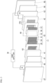
- FIG. 1 is a schematic configuration diagram showing an overall configuration of an electrolysis device 1 according to a first embodiment.
- the electrolysis device 1 is a device that generates hydrogen by electrolyzing water contained in an electrolyte.
- the electrolysis device 1 is an anion exchange membrane (AEM)-type electrolytic device.
- AEM anion exchange membrane
- the electrolysis device 1 is not limited to the above example and may be an electrolysis device having a different type, such as a device for electrolytic reduction of carbon dioxide.
- the electrolysis device 1 is provided with an electrolytic cell stack 10, an electrolyte supply unit 20, and a power supply unit 30.
- the electrolytic cell stack 10 is an assembly of a plurality of electrolytic cells 11.
- the electrolytic cell stack 10 is formed by arranging the plurality of electrolytic cells 11 in one direction.
- Each electrolytic cell 11 includes a cathode chamber Sa and an anode chamber Sb. The electrolytic cell 11 will be described later in detail.
- the electrolyte supply unit 20 is a supply unit that supplies an electrolyte to each electrolytic cell 11.
- the electrolyte is pure water or an alkaline aqueous solution.
- the electrolyte supply unit 20 includes a cathode-side supply unit 20a and an anode-side supply unit 20b.
- the cathode-side supply unit 20a is a supply unit that supplies an electrolyte to the cathode chamber Sa of each electrolytic cell 11.
- the cathode-side supply unit 20a includes a hydrogen gas-liquid separation device 21, a first pump 22, a hydrogen recovery unit 23, a first electrolyte supply unit 24, and piping lines L1 and L2.
- the hydrogen gas-liquid separation device 21 stores the electrolyte.
- a supply port of the hydrogen gas-liquid separation device 21 is connected to the cathode chamber Sa of the electrolytic cell 11 via the piping line L1.
- the first pump 22 is provided in the middle of the piping line L1 and sends the electrolyte stored in the hydrogen gas-liquid separation device 21 toward the cathode chamber Sa of the electrolytic cell 11.
- the return port of the hydrogen gas-liquid separation device 21 is connected to the cathode chamber Sa of the electrolytic cell 11 via the piping line L2.
- An electrolyte containing hydrogen generated in the electrolytic cell 11 flows into the hydrogen-gas-liquid separation device 21 from the electrolytic cell 11.
- the hydrogen gas-liquid separation device 21 has a gas-liquid separation unit that separates hydrogen contained in the electrolyte.
- the hydrogen separated from the electrolyte by the hydrogen gas-liquid separation device 21 is recovered by the hydrogen recovery unit 23.
- the hydrogen gas-liquid separation device 21 is replenished with the electrolyte from the first electrolyte supply unit 24.
- the anode-side supply unit 20b is a supply unit that supplies an electrolyte to the anode chamber Sb of each electrolytic cell 11.
- the anode-side supply unit 20b includes an oxygen gas-liquid separation device 26, a second pump 27, an oxygen recovery unit 28, a second electrolyte supply unit 29, and piping lines L3 and L4.
- the oxygen gas-liquid separation device 26 stores the electrolyte.
- a supply port of the oxygen gas-liquid separation device 26 is connected to the anode chamber Sb of the electrolytic cell 11 via the piping line L3.
- the second pump 27 is provided in the middle of the piping line L3 and sends the electrolyte stored in the oxygen gas-liquid separation device 26 toward the anode chamber Sb of the electrolytic cell 11.
- the return port of the oxygen gas-liquid separation device 26 is connected to the anode chamber Sb of the electrolytic cell 11 via the piping line L4.
- An electrolyte containing oxygen generated in the electrolytic cell 11 flows into the oxygen gas-liquid separation device 26 from the electrolytic cell 11.
- the oxygen gas-liquid separation device 26 has a gas-liquid separation unit that separates oxygen contained in the electrolyte. Oxygen separated from the electrolyte by the oxygen gas-liquid separation device 26 is recovered by the oxygen recovery unit 28.
- the oxygen gas-liquid separation device 26 is replenished with the electrolyte from the second electrolyte supply unit 29.
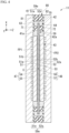
- FIG. 2 is a cross-sectional view schematically showing the electrolytic cell 11.
- the electrolytic cell 11 includes a first separator 41, a second separator 42, and a membrane electrode assembly 43.
- the first separator 41 is a member that defines one surface of an internal space S of the electrolytic cell 11.
- the internal space S is a space including the cathode chamber Sa and the anode chamber Sb described later.
- the first separator 41 has a rectangular plate shape and includes a metal member.
- a negative voltage is applied to the first separator 41 from the power supply unit 30 via a first current collector 61 (refer to FIG. 3 ) described later.
- the first separator 41 has a first end portion 41el (for example, a lower end portion) and a second end portion 41e2 (for example, an upper end portion) located on a side opposite to the first end portion 41e1.
- the above-described piping line L1 is connected to the first end portion 41e1 of the first separator 41.
- the above-described piping line L2 is connected to the second end portion 41e2 of the first separator 41.
- the first separator 41 has a first inner surface 41a that faces the cathode chamber Sa described later.
- a first flow path FP1 through which the electrolyte supplied from the piping line L1 flows is formed on the first inner surface 41a.
- the first flow path FP1 is a groove provided in the first inner surface 41a.
- the electrolyte that has flowed through the first flow path FP1 is discharged to the outside of the electrolytic cell 11 through the piping line L2.
- Each structure for example, a flow path structure
- FIG. 2 is merely an example and does not limit the content of the present embodiment.
- various structures can be used as the flow path structure depending on the size, purpose, and use environment of the device. The same applies to each structure shown in other drawings.
- the second separator 42 is a member that is disposed with an internal space S between the second separator 42 and at least part of the first separator 41 and that defines the other surface of the internal space S.
- the second separator 42 has a rectangular plate shape and includes a metal member.
- a positive voltage is applied to the second separator 42 from the power supply unit 30 via a second current collector 62 (refer to FIG. 3 ) described later.
- the first separator 41 and the second separator 42 included in the same electrolytic cell 11 form an electrolyzer 40 of the electrolytic cell 11 as a pair of separators.
- the second separator 42 has a first end portion 42e1 (for example, a lower end portion) and a second end portion 42e2 (for example, an upper end portion) located on a side opposite to the first end portion 42e1.
- the above-described piping line L3 is connected to the first end portion 42e1 of the second separator 42.
- the above-described piping line L4 is connected to the second end portion 42e2 of the second separator 42.
- the second separator 42 has a second inner surface 42a that faces the anode chamber Sb described later.
- a second flow path FP2 through which the electrolyte supplied from the piping line L3 flows is formed on the second inner surface 42a.
- the second flow path FP2 is a groove provided in the second inner surface 42a. The electrolyte that has flowed through the second flow path FP2 is discharged to the outside of the electrolytic cell 11 through the piping line L4.
- the first separator 41 of the electrolytic cell 11 included in the electrolytic cell stack 10 may be a bipolar plate having the same groove for a flow path (first flow path FP1, shown by a two-dot chain line in FIG. 2 ) on a surface 41b opposite to the first inner surface 41a in addition to the first inner surface 41a.
- the second separator 42 of the electrolytic cell 11 included in the electrolytic cell stack 10 may be a bipolar plate having the same groove for a flow path (second flow path FP2, shown by a two-dot chain line in FIG. 2 ) on a surface 42b opposite to the second inner surface 42a in addition to the second inner surface 42a.
- the grooves for flow paths provided on both surfaces of the first separator 41 may have different shapes and dispositions.
- the grooves for flow paths provided on both surfaces of the second separator 42 may have different shapes and dispositions.
- a membrane electrode assembly (MEA) 43 is a structure in which an ion exchange membrane, a catalyst, and a power supply body are assembled.
- the membrane electrode assembly 43 is disposed between the first separator 41 and the second separator 42 and is located in the internal space S.
- the membrane electrode assembly 43 includes a first ion exchange membrane 51, a second ion exchange membrane 52, an ionomer layer 53, a cathode catalyst layer 54, a cathode power supply body 55, an anode catalyst layer 56, and an anode power supply body 57.
- the first ion exchange membrane 51 is a membrane that selectively allows ions to permeate.
- the first ion exchange membrane 51 is a solid polymer electrolyte membrane.
- the first ion exchange membrane 51 is an anion exchange membrane (AEM) having hydroxide ion conductivity.
- AEM anion exchange membrane
- the first ion exchange membrane 51 is not limited to the above-described example and may be an ion exchange membrane having a type different from the above-described example.
- the first ion exchange membrane 51 has a rectangular sheet shape. The external size of the first ion exchange membrane 51 is smaller than the external size of the first separator 41 or the second separator 42.
- the first ion exchange membrane 51 is disposed between the first separator 41 and the second separator 42 and is located in the above-described internal space S.
- the first ion exchange membrane 51 has a first surface 51a facing the first inner surface 41a of the first separator 41 and a second surface 51b located on a side opposite to the first surface 51a.
- the cathode chamber Sa is defined between the first surface 51a of the first ion exchange membrane 51 and the first inner surface 41a of the first separator 41.
- the second ion exchange membrane 52 is a membrane that selectively allows ions to permeate.
- the second ion exchange membrane 52 is a solid polymer electrolyte membrane.
- the second ion exchange membrane 52 is an anion exchange membrane having hydroxide ion conductivity.
- the second ion exchange membrane 52 is not limited to the above-described example and may be an ion exchange membrane having a type different from the above-described example.
- the second ion exchange membrane 52 has a rectangular sheet shape. The external size of the second ion exchange membrane 52 is smaller than the external size of the first separator 41 or the second separator 42.
- the external size of the second ion exchange membrane 52 is the same as the external size of the first ion exchange membrane 51.
- the second ion exchange membrane 52 is disposed between the first separator 41 and the second separator 42 and is located in the above-described internal space S.
- the second ion exchange membrane 52 has a third surface 52a facing the second inner surface 42a of the second separator 42 and a fourth surface 52b located on a side opposite to the third surface 52a.
- the anode chamber Sb is defined between the third surface 52a of the second ion exchange membrane 52 and the second inner surface 42a of the second separator 42.
- the ordinal numbers such as “first” and “second” attached to the names of the components are for convenience of description.
- names such as “third” and “fourth” do not assume that the names “first” and “second” are present for the same member.
- the names of "third surface 52a” and “fourth surface 52b” of the second ion exchange membrane 52 do not assume that the first surface and the second surface are present in the second ion exchange membrane 52. Therefore, the names of "third surface 52a” and “fourth surface 52b” may be read as “first surface 52a” and "second surface 52b" of the second ion exchange membrane 52.
- the first ion exchange membrane 51 and the second ion exchange membrane 52 are integrated by facing the second surface 51b of the first ion exchange membrane 51 and the fourth surface 52b of the second ion exchange membrane 52.
- the phrase that "the first ion exchange membrane 51 and the second ion exchange membrane 52 are integrated" is not limited to a case where the first ion exchange membrane 51 and the second ion exchange membrane 52 are directly bonded to each other, and another layer (for example, an ionomer layer 53 described later) may be present between the first ion exchange membrane 51 and the second ion exchange membrane 52.
- the materials of the first ion exchange membrane 51 and the second ion exchange membrane 52 may be the same as or different from each other.
- the materials of the first ion exchange membrane 51 and the second ion exchange membrane 52 are selected as follows. That is, since the oxidation reaction does not occur in the cathode chamber Sa, the first ion exchange membrane 51 does not need to have high oxidation resistance. Therefore, as the first ion exchange membrane 51, for example, a membrane with a material having higher ion conductivity than the second ion exchange membrane 52 is employed. On the other hand, since an oxidation reaction occurs in the anode chamber Sb, it is preferable that the second ion exchange membrane 52 has high oxidation resistance. Therefore, as the second ion exchange membrane 52, for example, a membrane with a material having higher oxidation resistance than the first ion exchange membrane 51 is employed.
- the "membrane having high ion conductivity” is, for example, a membrane containing a polystyrene-based or tetraphenyl-based composition in the main chain and containing an imidazolium group or a quaternary ammonium group in the side chain.
- the "membrane having high oxidation resistance” is, for example, a membrane containing a polysulfone-based or bromobutylstyrene-based composition.
- the ionomer layer 53 is a layer for bonding the first ion exchange membrane 51 and the second ion exchange membrane 52.
- the ionomer layer 53 is a layer through which a hydroxide ion can pass.
- the ionomer layer 53 is provided between the second surface 51b of the first ion exchange membrane 51 and the fourth surface 52b of the second ion exchange membrane 52.
- the ionomer layer 53 is provided in the entire area of the second surface 51b of the first ion exchange membrane 51 and the entire area of the fourth surface 52b of the second ion exchange membrane 52.
- the thickness of the ionomer layer 53 is 10 nm or more and 10 ⁇ m or less.
- the first ion exchange membrane 51 and the second ion exchange membrane 52 are integrated through the ionomer layer 53.
- the cathode catalyst layer 54 is a layer that accelerates the chemical reaction in the cathode chamber Sa described above.
- the cathode catalyst layer 54 has a rectangular sheet shape.
- the external size of the cathode catalyst layer 54 is smaller than the external size of the first ion exchange membrane 51.
- the cathode catalyst layer 54 is disposed in the cathode chamber Sa and is adjacent to the first ion exchange membrane 51.
- the term of "adjacent" is not limited to a case where two members are independently adjacent to each other, and at least part of one member of the two members may enter the other member.
- part of the cathode catalyst layer 54 may enter a surface portion of the first ion exchange membrane 51.
- the cathode catalyst layer 54 is provided on the first surface 51a of the first ion exchange membrane 51.
- the cathode catalyst layer 54 is formed by applying a material of the cathode catalyst layer 54 to the first surface 51a of the first ion exchange membrane 51.
- a negative voltage is applied to the cathode catalyst layer 54 from the power supply unit 30 via the first separator 41 and the cathode power supply body 55, and the cathode catalyst layer 54 functions as part of the cathode 47 of the electrolytic cell 11.
- the cathode catalyst layer 54 As a material of the cathode catalyst layer 54, any material that accelerates the chemical reaction in the cathode chamber Sa described above may be used, and various materials can be used.
- the cathode catalyst layer 54 contains at least one of nickel, a nickel alloy, a cerium oxide, a lanthanum oxide, or platinum.
- the term of "OO oxide” may contain another material (another element) other than OO and oxygen.
- the cathode catalyst layer 54 may include another material such as carbon in addition to the above-described material.
- the cathode power supply body 55 is an electrical connection portion that transmits a voltage applied to the first separator 41 to the cathode catalyst layer 54.
- the cathode power supply body 55 is disposed in the cathode chamber Sa.
- the cathode power supply body 55 is located between the first inner surface 41a of the first separator 41 and the cathode catalyst layer 54 and is in contact with each of the first inner surface 41a of the first separator 41 and the cathode catalyst layer 54. At least part of the cathode power supply body 55 may overlap at least part of at least one of the first separator 41 or the cathode catalyst layer 54.
- the cathode power supply body 55 has a structure in which an electrolyte and gas can pass through the inside.
- the cathode power supply body 55 is made of a metal mesh structure, a sintered body, a fiber, or the like.
- the external size of the cathode power supply body 55 is the same as the external size of the cathode catalyst layer 54.
- the cathode 47 of the electrolytic cell 11 includes the cathode catalyst layer 54 and the cathode power supply body 55.
- the anode catalyst layer 56 is a layer that accelerates the chemical reaction in the anode chamber Sb described above.
- the anode catalyst layer 56 has a rectangular sheet shape.
- the external size of the anode catalyst layer 56 is smaller than the external size of the second ion exchange membrane 52.
- the anode catalyst layer 56 is disposed in the anode chamber Sb and is adjacent to the second ion exchange membrane 52. For example, part of the anode catalyst layer 56 may enter the surface portion of the second ion exchange membrane 52.
- the anode catalyst layer 56 is provided on the third surface 52a of the second ion exchange membrane 52.
- the anode catalyst layer 56 is formed by applying a material of the anode catalyst layer 56 to the third surface 52a of the second ion exchange membrane 52.
- a positive voltage is applied to the anode catalyst layer 56 from the power supply unit 30 via the second separator 42 and the anode power supply body 57, and the anode catalyst layer 56 functions as part of the anode 48 of the electrolytic cell 11.
- the anode catalyst layer 56 As a material of the anode catalyst layer 56, any material that accelerates the chemical reaction in the above-described anode chamber Sb may be used, and various materials can be used.
- the anode catalyst layer 56 contains at least one of nickel, a nickel alloy, a nickel oxide, a copper oxide, an iridium oxide, a niobium oxide, a lead oxide, and a bismuth oxide.
- the term of "XX oxide” may contain another material (another element) other than XX and oxygen.
- nickel oxide may contain elements such as iron and cobalt, in addition to nickel and oxygen.
- copper oxide may contain an element such as cobalt, in addition to copper and oxygen.
- iridium oxide may contain an element such as ruthenium, in addition to iridium and oxygen.
- ruthenium in addition to iridium and oxygen.
- lead oxide may contain an element such as ruthenium, in addition to lead and oxygen.
- bismuth oxide may contain an element such as ruthenium, in addition to bismuth and oxygen.
- the anode power supply body 57 is an electrical connection portion that transmits the voltage applied to the second separator 42 to the anode catalyst layer 56.
- the anode power supply body 57 is disposed in the anode chamber Sb.
- the anode power supply body 57 is located between the second inner surface 42a of the second separator 42 and the anode catalyst layer 56 and is in contact with each of the second inner surface 42a of the second separator 42 and the anode catalyst layer 56. At least part of the anode power supply body 57 may overlap at least part of at least one of the second separator 42 or the anode catalyst layer 56.
- the anode power supply body 57 has a structure in which an electrolyte and gas can pass through the inside.
- the anode power supply body 57 is made of a metal mesh structure, a sintered body, a fiber, or the like.
- the external size of the anode power supply body 57 is the same as the external size of the anode catalyst layer 56.
- the anode 48 of the electrolytic cell 11 includes the anode catalyst layer 56 and the anode power supply body 57.
- the first current collector 61 is an electrical connection portion that transmits the negative voltage applied from the power supply unit 30 to the first separator 41.
- the first current collector 61 is a metal plate member (for example, a copper plate).
- the first current collector 61 is in contact with the first separator 41 from a side of the electrolytic cell 11 opposite to the internal space S and is electrically connected to the first separator 41.
- a negative voltage desired for the electrolysis in the electrolytic cell 11 is applied to the first current collector 61 from the power supply unit 30.
- the first current collector 61 may be shared by two electrolytic cells 11 adjacent to each other in the electrolytic cell stack 10.
- the second current collector 62 is an electrical connection portion that transmits the positive voltage applied from the power supply unit 30 to the second separator 42.
- the second current collector 62 is a metal plate member (for example, a copper plate).
- the second current collector 62 is in contact with the second separator 42 from a side of the electrolytic cell 11 opposite to the internal space S and is electrically connected to the second separator 42.
- a positive voltage desired for the electrolysis in the electrolytic cell 11 is applied to the second current collector 62 from the power supply unit 30.
- the second current collector 62 may be shared by two electrolytic cells 11 adjacent to each other in the electrolytic cell stack 10.
- the first insulator 63 is a member that insulates an outer peripheral portion of the first separator 41 and an outer peripheral portion of the second separator 42.
- the first insulator 63 is a frame-shaped sheet member that is larger than the outer shape of the cathode catalyst layer 54 and the outer shape of the cathode power supply body 55 by one size.
- the first insulator 63 is attached to the first inner surface 41a of the first separator 41 and covers an end portion of the first inner surface 41a.
- the material of the first insulator 63 is not particularly limited as long as the material is an insulating material and is, for example, a sheet-like resin such as polytetrafluoroethylene (PTFE).
- the second insulator 64 is a member that insulates the outer peripheral portion of the first separator 41 and the outer peripheral portion of the second separator 42, similarly to the first insulator 63.
- the second insulator 64 is a frame-shaped sheet member that is larger than the outer shape of the anode catalyst layer 56 and the outer shape of the anode power supply body 57 by one size.
- the second insulator 64 is attached to the second inner surface 42a of the second separator 42 and covers an end portion of the second inner surface 42a.
- the material of the second insulator 64 is not particularly limited as long as the material is an insulating material and is, for example, a sheet-like resin such as PTFE.
- the first insulator 63 and the second insulator 64 can also be used as an integrated insulator.
- the first insulating material 65 is located between the first current collector 61 and the first end plate 67.
- the external size of the first insulating material 65 is the same as the external size of the first current collector 61 or larger than the external size of the first current collector 61.
- the second insulating material 66 is located between the second current collector 62 and the second end plate 68.
- the external size of the second insulating material 66 is the same as the external size of the second current collector 62 or larger than the external size of the second current collector 62.
- the second end plate 68 is located on a side opposite to the second insulating material 66 with respect to the internal space S of the electrolytic cell 11.
- the external size of the second end plate 68 is larger than the external size of the second insulating material 66.
- the electrolytic cell 11 is not limited to the above-described configuration.
- two adjacent electrolytic cells 11 among the plurality of electrolytic cells 11 may share the first separator 41 or the second separator 42, each of which is a bipolar plate.
- the current collector (the first current collector 61 or the second current collector 62), the insulator (the first insulator 63 or the second insulator 64), the insulating material (the first insulating material 65 or the second insulating material 66), and the end plate (the first end plate 67 or the second end plate 68) may not be present between the two adjacent electrolytic cells 11.
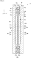
- FIG. 4 is a cross-sectional view showing the electrolytic cell 11.
- the external size of the first ion exchange membrane 51 is larger than each of the external size of the cathode catalyst layer 54 and the external size of the cathode power supply body 55.
- the area of the first ion exchange membrane 51 is larger than each of the area of the cathode catalyst layer 54 and the area of the cathode power supply body 55.
- the first ion exchange membrane 51 protrudes outside (on the outer peripheral side) the cathode catalyst layer 54 and the cathode power supply body 55 in a direction (for example, the X direction or the Y direction) orthogonal to the thickness direction (Z direction) of the membrane electrode assembly 43.
- outer side or “outer peripheral side” means a side away from the central portion C of the membrane electrode assembly 43 in a direction (for example, the X direction or the Y direction) orthogonal to the thickness direction (Z direction) of the membrane electrode assembly 43.
- the external size of the second ion exchange membrane 52 is larger than each of the external size of the anode catalyst layer 56 and the external size of the anode power supply body 57.
- the area of the second ion exchange membrane 52 is larger than each of the area of the anode catalyst layer 56 and the area of the anode power supply body 57.
- the second ion exchange membrane 52 protrudes on the outer peripheral side of the anode catalyst layer 56 and the anode power supply body 57 in a direction (for example, the X direction or the Y direction) orthogonal to the thickness direction (Z direction) of the membrane electrode assembly 43.
- the first ion exchange membrane 51 and the second ion exchange membrane 52 are collectively referred to as an "ion exchange membrane laminate 59".
- the electrolytic cell 11 includes a support portion 70 and a sealing portion 80.
- the support portion 70 is a member that supports the membrane electrode assembly 43 inside the electrolytic cell 11.
- the sealing portion 80 is a member that closes the internal space S between the first separator 41 and the second separator 42.
- the support portion 70 is disposed between the first separator 41 and the second separator 42.
- the support portion 70 is located inside (on the inner peripheral side) an outer edge portion 59e of the ion exchange membrane laminate 59 and supports the ion exchange membrane laminate 59.
- the term "outer edge portion” means an edge portion that is separated from the central portion C of the membrane electrode assembly 43 in a direction (for example, the X direction or the Y direction) orthogonal to the thickness direction (Z direction) of the membrane electrode assembly 43.
- the term of "inside” or “inner peripheral side” means an inside (a side close to the central portion C) as viewed from the central portion C of the membrane electrode assembly 43.
- the support portion 70 includes a first support portion 71 and a second support portion 72.
- the first support portion 71 is a support portion on the cathode side.
- the first support portion 71 is disposed between the first inner surface 41a of the first separator 41 and the first surface 51a of the first ion exchange membrane 51.
- the first support portion 71 is located inside (on the inner peripheral side) the outer edge portion 59e (for example, an outer edge portion 51e of the first ion exchange membrane 51) of the ion exchange membrane laminate 59.
- the first support portion 71 is sandwiched between the first inner surface 41a (or the first insulator 63) of the first separator 41 and the first surface 51a of the first ion exchange membrane 51 at a position outside (on the outer peripheral side) the cathode catalyst layer 54 and the cathode power supply body 55 and supports the first ion exchange membrane 51 with respect to the first inner surface 41a of the first separator 41.
- the first support portion 71 is formed in an annular shape (for example, a frame shape) along the outer edge portion 51e of the first ion exchange membrane 51, and in an annular shape that is smaller than the outer edge portion 51e of the first ion exchange membrane 51 by one size.
- the second support portion 72 is a support portion on the anode side.
- the second support portion 72 is disposed between the second inner surface 42a of the second separator 42 and the third surface 52a of the second ion exchange membrane 52.
- the second support portion 72 is located inside (on the inner peripheral side) the outer edge portion 59e (for example, the outer edge portion 52e of the second ion exchange membrane 52) of the ion exchange membrane laminate 59.
- the second support portion 72 is sandwiched between the second inner surface 42a of the second separator 42 and the third surface 52a of the second ion exchange membrane 52 at a position outside (on the outer peripheral side) the anode catalyst layer 56 and the anode power supply body 57 and supports the second ion exchange membrane 52 with respect to the second inner surface 42a of the second separator 42.
- the second support portion 72 is formed in an annular shape (for example, a frame shape) along the outer edge portion 52e of the second ion exchange membrane 52, and in an annular shape that is smaller than the outer edge portion 52e of the second ion exchange membrane 52 by one size.
- the sealing portion 80 is disposed between the first separator 41 and the second separator 42.
- the sealing portion 80 is located outside (on the outer peripheral side) the outer edge portion 59e (that is, the outer edge portion 51e of the first ion exchange membrane 51 and the outer edge portion 52e of the second ion exchange membrane 52) of the ion exchange membrane laminate 59 and seals the internal space S of the electrolytic cell 11.
- the sealing portion 80 includes a first sealing portion 81 and a second sealing portion 82.
- the first sealing portion 81 and the second sealing portion 82 may be formed integrally. That is, the first sealing portion 81 and the second sealing portion 82 may be one member.
- the sealing portion 80 may be formed integrally with at least one of the first insulator 63 and the second insulator 64 described above.
- the second sealing portion 82 is a sealing portion on the anode side.
- the second sealing portion 82 is located outside the outer edge portion 59e of the ion exchange membrane laminate 59.
- the second sealing portion 82 is sandwiched between the second inner surface 42a of the second separator 42 and the first sealing portion 81 and seals part of the outer peripheral side of the internal space S.
- the second sealing portion 82 is formed in an annular shape (for example, a frame shape) along the outer edge portion 52e of the second ion exchange membrane 52, and in an annular shape that is larger than the outer edge portion 52e of the second ion exchange membrane 52 by one size.
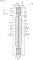
- FIG. 5 is a cross-sectional view showing the method of manufacturing the membrane electrode assembly 43.
- the cathode catalyst layer 54 is provided on the first surface 51a of the first ion exchange membrane 51.
- the cathode catalyst layer 54 is formed by applying (coating) a material of the cathode catalyst layer 54 to the first surface 51a of the first ion exchange membrane 51 and pressing the applied material of the cathode catalyst layer 54 and the first ion exchange membrane 51 at a predetermined temperature and a predetermined pressure.
- the anode catalyst layer 56 is provided on the third surface 52a of the second ion exchange membrane 52.
- the anode catalyst layer 56 is formed by applying (coating) a material of the anode catalyst layer 56 to the third surface 52a of the second ion exchange membrane 52 and pressing the applied material of the anode catalyst layer 56 and the second ion exchange membrane 52 at a predetermined temperature and a predetermined pressure.
- a coating method, a chemical vapor deposition (CVD) method, an electroless plating method, a method using a catalyst ink, a method of applying a catalyst by spraying, or the like can be appropriately used.
- the first ion exchange membrane 51 and the second ion exchange membrane 52 are integrated with each other by facing the second surface 51b of the first ion exchange membrane 51 and the fourth surface 52b of the second ion exchange membrane 52 face each other.
- the first ion exchange membrane 51 and the second ion exchange membrane 52 are bonded to each other through the ionomer layer 53 by making the second surface 51b of the first ion exchange membrane 51 and the fourth surface 52b of the second ion exchange membrane 52 face each other and pressing the first ion exchange membrane 51 and the second ion exchange membrane 52 at a predetermined temperature and a predetermined pressure, in a state where each of the second surface 51b of the first ion exchange membrane 51 and the fourth surface 52b of the second ion exchange membrane 52 are applied (coated) with the material of the ionomer layer 53.
- the cathode power supply body 55 is bonded to the cathode catalyst layer 54 from a side opposite to the first ion exchange membrane 51.
- the bond of the cathode power supply body 55 to the cathode catalyst layer 54 is performed, for example, by applying pressure by pressing.
- the anode power supply body 57 is bonded to the anode catalyst layer 56 from a side opposite to the second ion exchange membrane 52.
- the bond of the anode power supply body 57 to the anode catalyst layer 56 is performed, for example, by applying pressure.
- a structure in which a cathode catalyst layer and an anode catalyst layer are provided on both surfaces of one ion exchange membrane will be considered.
- the membrane electrode assembly 43 includes the first ion exchange membrane 51 and the second ion exchange membrane 52.
- the cathode catalyst layer 54 on one surface of the first ion exchange membrane 51, providing the anode catalyst layer 56 on one surface of the second ion exchange membrane 52 and then integrating the first ion exchange membrane 51 and the second ion exchange membrane 52, it is possible to suppress the influence of the uneven portion of the catalyst layer present on one surface of the ion exchange membrane on the manufacturing of the catalyst layer on the other surface of the ion exchange membrane. As a result, it is possible to suppress the occurrence of a portion that causes a defect such as a short circuit.
- the thickness of the ion exchange membrane (the thickness of the first ion exchange membrane 51 and the second ion exchange membrane 52) is likely to be reduced.
- the performance of the membrane electrode assembly 43 can be improved.
- two ion exchange membranes, each of which has a catalyst layer on one surface can be separately handled, handling in the manufacturing process is facilitated, and productivity can be improved.
- FIG. 6 is a cross-sectional view showing an electrolytic cell 11 according to a modification example of the first embodiment.
- the ionomer layer 53 is provided between the first ion exchange membrane 51 and the second ion exchange membrane 52.
- the ionomer layer 53 is not provided between the first ion exchange membrane 51 and the second ion exchange membrane 52. That is, the second surface 51b of the first ion exchange membrane 51 and the fourth surface 52b of the second ion exchange membrane 52 are in contact with each other.
- the first ion exchange membrane 51 and the second ion exchange membrane 52 are integrated by pressing (compressing) the second surface 51b of the first ion exchange membrane 51 and the fourth surface 52b of the second ion exchange membrane 52 by facing each other.
- the step of providing the cathode catalyst layer 54 on the first ion exchange membrane 51 and the step of providing the anode catalyst layer 56 on the second ion exchange membrane 52 can be separately performed, it is possible to suppress the influence of the uneven portion of the catalyst layer present on one surface of the ion exchange membrane on the manufacturing of the catalyst layer on the other surface of the ion exchange membrane.
- the second embodiment is different from the first embodiment in that the area of the anode 48 is larger than the area of the cathode 47. Configurations other than those described below are the same as the configurations of the first embodiment.
- FIG. 7 is a cross-sectional view showing an electrolytic cell 11A of a second embodiment.
- the area of the anode 48 is larger than the area of the cathode 47.
- the area of the anode catalyst layer 56 is larger than the area of the cathode catalyst layer 54.
- the area of the anode power supply body 57 is larger than the area of the cathode power supply body 55.
- the area ratio of the anode 48 to the cathode 47 is more than 1.0 and 1.3 or less.
- the area ratio of the anode 48 to the cathode 47 is set such that a rate of increase in the overvoltage of the anode 48 due to the progress of deterioration is less than 2 times (more preferably less than 1.5 times) as compared with a rate of increase in the overvoltage of the cathode 47.
- FIG. 8 is a graph describing the action of the electrolytic cell 11A.
- FIG. 8 is a graph showing test results of the current-voltage characteristics in the electrolytic cell of the second comparative example in which the area of the anode and the area of the cathode are the same.
- the term of "cycle" means a predetermined period set in advance. As shown in FIG. 8 , it is found that the overvoltage increases as the number of cycles increases (that is, as the use time increases) in the electrolytic cell of the second comparative example.
- the area of the anode 48 is formed larger than the area of the cathode 47. According to such a configuration, the oxidation reaction in the anode 48 can be dispersed over a wide area of the anode 48. As a result, it is possible to suppress the deterioration of the anode 48 from being larger than that of the cathode 47, as compared with the above second comparative example. When it is possible to suppress the deterioration of the anode 48 from being larger than that of the cathode 47, it is possible to suppress an increase in the overvoltage and improve the performance and the life of the electrolytic cell 11A.
- the cathode catalyst layer 54 is provided on the first ion exchange membrane 51, and the anode catalyst layer 56 is provided on the second ion exchange membrane 52. According to such a configuration, it is easy to easily form the cathode catalyst layer 54 and the anode catalyst layer 56 having different areas. Therefore, according to the present embodiment, it is possible to improve the productivity of the membrane electrode assembly 43 in which the area of the anode 48 is larger than the area of the cathode 47.
- the current is likely to flow around at an end portion of the catalyst layer, and the current density is likely to increase at the end portion of the catalyst layer. Therefore, in a case where the areas of the cathode catalyst layer and the anode catalyst layer are the same as in the second comparative example, since the end portions of the catalyst layers having a high current density face each other, local deterioration is likely to increase at the end portion of each catalyst layer.
- the anode catalyst layer 56 is larger than the cathode catalyst layer 54, the end portions of each catalyst layer having a high current density are shifted from each other. As a result, the deterioration is unlikely to increase at the end portion of each catalyst layer. From this viewpoint as well, it is possible to suppress an increase in the overvoltage and improve the performance and the life of the electrolytic cell 11A.
- the rate of increase in the reaction resistance in the anode 48 is 2 times or more as compared with the rate of increase in the reaction resistance in the cathode 47.
- the area ratio of the anode 48 to the cathode 47 is set based on the rate of increase in reaction resistance in the anode 48 and the rate of increase in reaction resistance in the cathode 47.
- the area ratio of the anode 48 to the cathode 47 is adjusted and determined such that a difference between the rate of increase in the reaction resistance of the anode 48 and the rate of increase in the reaction resistance of the cathode 47 is equal to or less than a predetermined standard (for example, less than 2 times, and more preferably less than 1.5 times).
- the catalyst carrying amount of the anode catalyst layer 56 is equal to or greater than the catalyst carrying amount of the cathode catalyst layer 54.
- the term of "catalyst carrying amount” means the weight of the catalyst per unit area [mg/cm 2 ].
- the third embodiment is different from the second embodiment in that the thickness of the anode catalyst layer 56 is larger than the thickness of the cathode catalyst layer 54.
- the volume ratio (or the catalyst carrying amount ratio) of the anode catalyst layer 56 to the cathode catalyst layer 54 is set such that the rate of increase in the overvoltage of the anode 48 due to the progress of deterioration is less than 2 times (more preferably less than 1.5 times) as compared with the rate of increase in the overvoltage of the cathode 47.
- the volume ratio of the anode 48 to the cathode 47 is adjusted and determined such that a difference between the rate of increase in the reaction resistance of the anode 48 and the rate of increase in the reaction resistance of the cathode 47 is equal to or less than a predetermined standard (for example, less than 2 times, and more preferably less than 1.5 times).
- the member that bonds the first ion exchange membrane 51 and the second ion exchange membrane 52 is not limited to the ionomer layer 53 and may be an adhesive layer made of another material having hydroxide ion conductivity.
- the membrane electrode assembly 43, the electrolytic cells 11, 11A, and 11B, the electrolysis device 1, and the method of manufacturing the membrane electrode assembly 43, which are described in each embodiment, are grasped as follows, for example.
Landscapes
- Chemical & Material Sciences (AREA)
- Engineering & Computer Science (AREA)
- Chemical Kinetics & Catalysis (AREA)
- Electrochemistry (AREA)
- Materials Engineering (AREA)
- Metallurgy (AREA)
- Organic Chemistry (AREA)
- Electrolytic Production Of Non-Metals, Compounds, Apparatuses Therefor (AREA)
- Electrodes For Compound Or Non-Metal Manufacture (AREA)
Applications Claiming Priority (2)
| Application Number | Priority Date | Filing Date | Title |
|---|---|---|---|
| JP2022090938A JP2023177957A (ja) | 2022-06-03 | 2022-06-03 | 膜電極接合体、電解セル、電解装置、および膜電極接合体の製造方法 |
| PCT/JP2023/008090 WO2023233740A1 (fr) | 2022-06-03 | 2023-03-03 | Assemblage électrode-membrane, cellule d'électrolyse, dispositif d'électrolyse et procédé de production d'assemblage électrode-membrane |
Publications (2)
| Publication Number | Publication Date |
|---|---|
| EP4516967A1 true EP4516967A1 (fr) | 2025-03-05 |
| EP4516967A4 EP4516967A4 (fr) | 2026-03-11 |
Family
ID=89026061
Family Applications (1)
| Application Number | Title | Priority Date | Filing Date |
|---|---|---|---|
| EP23815503.0A Pending EP4516967A4 (fr) | 2022-06-03 | 2023-03-03 | Assemblage électrode-membrane, cellule d'électrolyse, dispositif d'électrolyse et procédé de production d'assemblage électrode-membrane |
Country Status (5)
| Country | Link |
|---|---|
| EP (1) | EP4516967A4 (fr) |
| JP (1) | JP2023177957A (fr) |
| AU (1) | AU2023281998A1 (fr) |
| TW (1) | TWI863169B (fr) |
| WO (1) | WO2023233740A1 (fr) |
Families Citing this family (4)
| Publication number | Priority date | Publication date | Assignee | Title |
|---|---|---|---|---|
| WO2025149794A1 (fr) * | 2024-01-11 | 2025-07-17 | Sungreenh2 Pte. Ltd. | Système d'électrolyseur et procédé d'utilisation |
| JP7618075B1 (ja) | 2024-01-16 | 2025-01-20 | 三菱重工業株式会社 | 電解セル、及び電解装置 |
| JP7618086B1 (ja) | 2024-03-28 | 2025-01-20 | 三菱重工業株式会社 | 電解セル、及び電解装置 |
| KR20260037452A (ko) * | 2024-09-10 | 2026-03-17 | 롯데케미칼 주식회사 | 전기화학적 이산화탄소 환원 장치 |
Family Cites Families (13)
| Publication number | Priority date | Publication date | Assignee | Title |
|---|---|---|---|---|
| JP3504021B2 (ja) | 1994-12-08 | 2004-03-08 | ジャパンゴアテックス株式会社 | 電気化学装置用電極とその製造方法 |
| US20050014056A1 (en) * | 2003-07-14 | 2005-01-20 | Umicore Ag & Co. Kg | Membrane electrode unit for electrochemical equipment |
| JP5622544B2 (ja) * | 2010-12-03 | 2014-11-12 | 高砂熱学工業株式会社 | 水素製造セル及び水素製造装置 |
| JPWO2014087958A1 (ja) * | 2012-12-03 | 2017-01-05 | Jsr株式会社 | 膜−電極接合体の製造方法、膜−電極接合体、膜−電極接合体形成用積層体、固体高分子型燃料電池および水電解装置 |
| CN107002260B (zh) * | 2014-09-29 | 2019-05-10 | 巴斯夫欧洲公司 | 膜电极组件,包含膜电极组件的反应器和分离氢气的方法 |
| JP2017087168A (ja) * | 2015-11-13 | 2017-05-25 | シャープ株式会社 | 水素含有水生成装置および水素含有水の生成方法 |
| EP3529396A4 (fr) * | 2017-04-19 | 2020-10-14 | PH Matter, LLC | Cellule électrochimique et son procédé d'utilisation |
| JP6952664B2 (ja) | 2018-03-22 | 2021-10-20 | 株式会社東芝 | 積層電解質膜、膜電極複合体、水電解用セル、スタック、水電解装置および水素利用システム |
| EP4166692B1 (fr) * | 2020-06-11 | 2024-09-11 | University of Yamanashi | Catalyseur d'électrode et cellule électrochimique à membrane échangeuse d'anions |
| JP6963709B1 (ja) * | 2020-06-18 | 2021-11-10 | 日本碍子株式会社 | 電気化学セル、及び電気化学セル用電解質膜 |
| JP6963710B1 (ja) * | 2020-06-18 | 2021-11-10 | 日本碍子株式会社 | 電気化学セル、及び電気化学セル用電解質膜 |
| JP7104110B2 (ja) * | 2020-08-06 | 2022-07-20 | 本田技研工業株式会社 | 水電解システム |
| JP7532233B2 (ja) | 2020-12-08 | 2024-08-13 | キヤノン株式会社 | 画像形成装置 |
-
2022
- 2022-06-03 JP JP2022090938A patent/JP2023177957A/ja active Pending
-
2023
- 2023-03-03 EP EP23815503.0A patent/EP4516967A4/fr active Pending
- 2023-03-03 WO PCT/JP2023/008090 patent/WO2023233740A1/fr not_active Ceased
- 2023-03-03 AU AU2023281998A patent/AU2023281998A1/en active Pending
- 2023-03-14 TW TW112109271A patent/TWI863169B/zh active
Also Published As
| Publication number | Publication date |
|---|---|
| TWI863169B (zh) | 2024-11-21 |
| AU2023281998A1 (en) | 2024-12-12 |
| JP2023177957A (ja) | 2023-12-14 |
| TW202413725A (zh) | 2024-04-01 |
| WO2023233740A1 (fr) | 2023-12-07 |
| EP4516967A4 (fr) | 2026-03-11 |
Similar Documents
| Publication | Publication Date | Title |
|---|---|---|
| EP4516967A1 (fr) | Assemblage électrode-membrane, cellule d'électrolyse, dispositif d'électrolyse et procédé de production d'assemblage électrode-membrane | |
| US7951284B2 (en) | Electrolysis apparatus, electrochemical reaction membrane apparatus, porous electrical conductor, and production method thereof | |
| EP4343031A2 (fr) | Séparateur et électrolyseur d'eau | |
| EP4343030A2 (fr) | Électrolyseur d'eau | |
| US12506166B2 (en) | Membrane electrode assembly, and production method for membrane electrode assembly | |
| EP4516968A1 (fr) | Cellule d'électrolytique et électrolyseur | |
| KR20140133301A (ko) | 전기화학셀용 막전극 접합체 | |
| EP4610403A1 (fr) | Assemblage membrane-électrodes et procédé de fabrication d'assemblage membrane-électrodes | |
| EP4534729A2 (fr) | Structure d'électrode | |
| EP4534731A2 (fr) | Structure d'électrode | |
| EP4640924A1 (fr) | Cellule électrochimique et dispositif électrolytique | |
| TWI920895B (zh) | 電解單元及電解裝置 | |
| JP7661548B1 (ja) | 電解セル、及び電解装置 | |
| US20250101611A1 (en) | Electrode structure | |
| EP4632113A1 (fr) | Cellule électrolytique et appareil électrolytique | |
| JP7207591B1 (ja) | 水電解セル、水電解セルの製造方法 | |
| EP4435146A2 (fr) | Structure d'électrode et électrolyseur d'eau | |
| EP4442861A1 (fr) | Structure d'électrode et électrolyseur d'eau | |
| TW202532693A (zh) | 電解單元及電解裝置 | |
| TW202532694A (zh) | 分隔件及電解裝置 |
Legal Events
| Date | Code | Title | Description |
|---|---|---|---|
| STAA | Information on the status of an ep patent application or granted ep patent |
Free format text: STATUS: THE INTERNATIONAL PUBLICATION HAS BEEN MADE |
|
| PUAI | Public reference made under article 153(3) epc to a published international application that has entered the european phase |
Free format text: ORIGINAL CODE: 0009012 |
|
| STAA | Information on the status of an ep patent application or granted ep patent |
Free format text: STATUS: REQUEST FOR EXAMINATION WAS MADE |
|
| 17P | Request for examination filed |
Effective date: 20241128 |
|
| AK | Designated contracting states |
Kind code of ref document: A1 Designated state(s): AL AT BE BG CH CY CZ DE DK EE ES FI FR GB GR HR HU IE IS IT LI LT LU LV MC ME MK MT NL NO PL PT RO RS SE SI SK SM TR |
|
| DAV | Request for validation of the european patent (deleted) | ||
| DAX | Request for extension of the european patent (deleted) | ||
| A4 | Supplementary search report drawn up and despatched |
Effective date: 20260205 |
|
| RIC1 | Information provided on ipc code assigned before grant |
Ipc: C25B 9/23 20210101AFI20260130BHEP Ipc: C25B 1/04 20210101ALI20260130BHEP Ipc: C25B 9/00 20210101ALI20260130BHEP Ipc: C25B 9/21 20210101ALI20260130BHEP Ipc: C25B 9/60 20210101ALI20260130BHEP Ipc: C25B 9/65 20210101ALI20260130BHEP Ipc: C25B 9/75 20210101ALI20260130BHEP Ipc: C25B 9/77 20210101ALI20260130BHEP Ipc: C25B 11/052 20210101ALI20260130BHEP Ipc: C25B 13/04 20210101ALI20260130BHEP Ipc: C25B 13/02 20060101ALI20260130BHEP Ipc: C25B 13/08 20060101ALI20260130BHEP Ipc: C25B 11/075 20210101ALN20260130BHEP Ipc: C25B 11/077 20210101ALN20260130BHEP Ipc: C25B 11/081 20210101ALN20260130BHEP Ipc: C25B 11/089 20210101ALN20260130BHEP |