EP4517007A2 - Dispositif de profilage de trajets - Google Patents
Dispositif de profilage de trajets Download PDFInfo
- Publication number
- EP4517007A2 EP4517007A2 EP24189760.2A EP24189760A EP4517007A2 EP 4517007 A2 EP4517007 A2 EP 4517007A2 EP 24189760 A EP24189760 A EP 24189760A EP 4517007 A2 EP4517007 A2 EP 4517007A2
- Authority
- EP
- European Patent Office
- Prior art keywords
- dozer
- blades
- path
- central
- lateral
- Prior art date
- Legal status (The legal status is an assumption and is not a legal conclusion. Google has not performed a legal analysis and makes no representation as to the accuracy of the status listed.)
- Pending
Links
Images




Classifications
-
- E—FIXED CONSTRUCTIONS
- E02—HYDRAULIC ENGINEERING; FOUNDATIONS; SOIL SHIFTING
- E02F—DREDGING; SOIL-SHIFTING
- E02F3/00—Dredgers; Soil-shifting machines
- E02F3/04—Dredgers; Soil-shifting machines mechanically-driven
- E02F3/28—Dredgers; Soil-shifting machines mechanically-driven with digging tools mounted on a dipper- or bucket-arm, i.e. there is either one arm or a pair of arms, e.g. dippers, buckets
- E02F3/36—Component parts
- E02F3/3604—Devices to connect tools to arms, booms or the like
- E02F3/3609—Devices to connect tools to arms, booms or the like of the quick acting type, e.g. controlled from the operator seat
-
- E—FIXED CONSTRUCTIONS
- E02—HYDRAULIC ENGINEERING; FOUNDATIONS; SOIL SHIFTING
- E02F—DREDGING; SOIL-SHIFTING
- E02F3/00—Dredgers; Soil-shifting machines
- E02F3/04—Dredgers; Soil-shifting machines mechanically-driven
- E02F3/76—Graders, bulldozers, or the like with scraper plates or ploughshare-like elements; Levelling scarifying devices
- E02F3/7622—Scraper equipment with the scraper blade mounted on a frame to be hitched to the tractor by bars, arms, chains or the like, the frame having no ground supporting means of its own, e.g. drag scrapers
-
- E—FIXED CONSTRUCTIONS
- E02—HYDRAULIC ENGINEERING; FOUNDATIONS; SOIL SHIFTING
- E02F—DREDGING; SOIL-SHIFTING
- E02F3/00—Dredgers; Soil-shifting machines
- E02F3/04—Dredgers; Soil-shifting machines mechanically-driven
- E02F3/76—Graders, bulldozers, or the like with scraper plates or ploughshare-like elements; Levelling scarifying devices
- E02F3/80—Component parts
- E02F3/815—Blades; Levelling or scarifying tools
- E02F3/8155—Blades; Levelling or scarifying tools provided with movable parts, e.g. cutting discs, vibrating teeth or the like
-
- E—FIXED CONSTRUCTIONS
- E02—HYDRAULIC ENGINEERING; FOUNDATIONS; SOIL SHIFTING
- E02F—DREDGING; SOIL-SHIFTING
- E02F3/00—Dredgers; Soil-shifting machines
- E02F3/04—Dredgers; Soil-shifting machines mechanically-driven
- E02F3/96—Dredgers; Soil-shifting machines mechanically-driven with arrangements for alternate or simultaneous use of different digging elements
- E02F3/963—Arrangements on backhoes for alternate use of different tools
Definitions
- the present invention relates to a device for roof-shaped profiling of the surface layer of paths, in particular forest paths.
- the path surface is usually worked in such a way that slightly inclined areas are created on both sides of the path in order to support water drainage on both sides of the path. This prevents large amounts of water from accumulating on the path during prolonged periods of rain.
- graders are usually used. These have a so-called grader blade that can be placed on the path surface, i.e. the surface layer of the path. This grader blade is a type of dozer blade. This intervenes in the surface layer and is used to restore or recreate the profile of the surface layer in order to ensure sufficient water drainage from the path body.
- this profile is often changed, which can have adverse consequences for the durability of the paths. By restoring the path profile, the durability and longevity of such paths can be ensured.
- the present invention is based on the object of overcoming the disadvantages of the devices from the prior art.
- the invention is based in particular on the object of enabling a quick and simple profiling of paths, in particular forest paths or forest trails.
- the device according to the invention comprises a combination of three dozer blades, with a central dozer blade and two pivotally mounted lateral dozer blades being provided. Because the lateral dozer blades can be pivoted, they can be positioned in such a way that they can be used to create opposing path surfaces with a desired incline.
- the great advantage of the device according to the invention is that a fully profiled path can usually be created in a single work step.
- the device according to the invention only has to be pushed or pulled over the path to be worked once, so that the dozer blades penetrate the surface layer of the path to be worked with their soil processing edges and create the desired profile.
- the side dozer blades are pivotable, preferably pivotable about a substantially horizontal axis, on the central dozer blade, in particular in the area of the two ends of the central dozer blade.
- This embodiment makes it ideally possible to create a roof-shaped profile for a path, whereby the top of the path roof can be rounded or slightly flattened.
- paths with "roof peaks" of different widths can be created.
- the side dozer blades can be swiveled through 360°. This means that the side dozer blades can be swiveled so that they are positioned vertically to the ground and pointing upwards. In this position, the device, which is usually mounted on a vehicle, can be optimally transported when not in use without the risk of damaging the side dozer blades.
- the side dozer blades can be pivoted and preferably fixed in a desired position using actuating means, preferably hydraulic and/or pneumatic cylinders.
- actuating means preferably hydraulic and/or pneumatic cylinders.
- the pivoting ability with such actuating means is extremely efficient and simple in construction.
- hydraulic and/or pneumatic circuits of a towing vehicle can be used.
- the fixing of the side dozer blades by such actuating means when the device is in use is particularly advantageous. In this way, a desired pivoting of the side dozer blades can first be set and fixed, in which the soil processing edges of the side dozer blades are positioned in the desired manner on the soil processing edge of the central dozer blade. The device can then be pulled or pushed over the soil to work it, which is usually done using a motor-driven vehicle.
- the dozer blades can be swiveled using slewing rings.
- the leveling blades have straight soil working edges. This ensures that the soil surfaces are even in order to ensure the best possible water drainage.
- a preferred embodiment of the invention is characterized by a device for coupling the device to a vehicle, such as an excavator, a grader or the like, wherein the device is preferably attached to the central Dozer blade is arranged.
- a vehicle such as an excavator, a grader or the like
- the device according to the invention can be coupled quickly and easily to a towing or pushing vehicle.
- a possible embodiment is shown in the figures.
- the device according to the invention is advantageously designed to be rotatable, in particular rotatable by 360°, wherein the device is preferably coupled to a slewing ring, in particular to a slewing ring in combination with a tilt motor, which slewing ring and/or tilt motor is preferably connected to the device for coupling the device to a vehicle.
- This rotatability of the entire device makes it possible, for example, to pivot the device by 90° in order to be able to transport the device easily when not in use.
- the present invention further relates to a vehicle, in particular an excavator, a grader or the like, comprising a device according to one of claims 1 to 8.
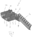
- the device 1 shown comprises a central dozer blade 2 and two lateral dozer blades 3a and 3b pivotably mounted on the central dozer blade 2.
- the central dozer blade 2 has a straight soil working edge 4.
- the lateral dozer blades 3a and 3b also each have a straight soil working edge 5a, 5b.
- the lateral dozer blades 3a and 3b are each pivotably mounted on the central dozer blade 2 about a horizontal axis 6.
- the lateral dozer blades 3a and 3b are arranged at the two end areas of the central dozer blade 2. This and the pivotability of the lateral dozer blades 3a and 3b about the horizontal axes 6 is particularly the Figure 1 easy to remove.
- the side dozer blades 3a and 3b can each be pivoted by 360° in the device 1.
- the side dozer blades 3a and 3b can be pivoted by means of hydraulic cylinders (not shown here), which are an integral part of a towing vehicle according to the invention (not shown here). These hydraulic cylinders are articulated to levers which are arranged on the two upper edges of the side dozer blades 3a and 3b.
- a device 8 for coupling the device 1 to a vehicle is arranged on the rear side 7 of the central dozer blade 2.
- the device 8 comprises two parallel coupling plates 9, each of which has fastening hooks 10 for fastening the device 8 to a towing vehicle.
- the coupling plates 9 are connected to one another via a connecting plate 11.
- a desired angle ⁇ is set between the soil working edges 5a, 5b and the soil working edge 4. As shown for example in the Figure 1 As can be clearly seen, this angle ⁇ is an obtuse angle. If such angles ⁇ are set between the edges mentioned by pivoting the side blades 3a and 3b, the set position of the blades 3a and 3b is fixed by means of the hydraulic cylinders mentioned above.
- the device 1 is now pulled over the ground to be worked by a towing vehicle, whereby the device 1 is positioned so that the Soil tillage edges 4, 5a and 5b penetrate into the top layer of the soil to be tilled. As the towing vehicle moves, loose path material is removed, ultimately creating a path with a roof-shaped profile.
- Figure 6 shows a cross-section through a finished base 12.
- the base 12 has two laterally sloping base surfaces 13a and 13b.
- the tip 14 of the base 12 is slightly rounded.
Landscapes
- Engineering & Computer Science (AREA)
- Mechanical Engineering (AREA)
- Mining & Mineral Resources (AREA)
- Civil Engineering (AREA)
- General Engineering & Computer Science (AREA)
- Structural Engineering (AREA)
- Buildings Adapted To Withstand Abnormal External Influences (AREA)
- Scissors And Nippers (AREA)
- Devices For Post-Treatments, Processing, Supply, Discharge, And Other Processes (AREA)
- Seal Device For Vehicle (AREA)
- Soil Working Implements (AREA)
Applications Claiming Priority (1)
| Application Number | Priority Date | Filing Date | Title |
|---|---|---|---|
| DE202023104859.5U DE202023104859U1 (de) | 2023-08-25 | 2023-08-25 | Vorrichtung zur Profilierung von Wegen |
Publications (2)
| Publication Number | Publication Date |
|---|---|
| EP4517007A2 true EP4517007A2 (fr) | 2025-03-05 |
| EP4517007A3 EP4517007A3 (fr) | 2025-05-07 |
Family
ID=88599596
Family Applications (1)
| Application Number | Title | Priority Date | Filing Date |
|---|---|---|---|
| EP24189760.2A Pending EP4517007A3 (fr) | 2023-08-25 | 2024-07-19 | Dispositif de profilage de trajets |
Country Status (2)
| Country | Link |
|---|---|
| EP (1) | EP4517007A3 (fr) |
| DE (1) | DE202023104859U1 (fr) |
Family Cites Families (4)
| Publication number | Priority date | Publication date | Assignee | Title |
|---|---|---|---|---|
| US6442877B1 (en) * | 2000-10-12 | 2002-09-03 | Blizzard Corporation | Plow with rear mounted, adjustable wing |
| EP3719210B1 (fr) * | 2019-04-04 | 2021-06-23 | Rädlinger Maschinen- und Stahlbau GmbH | Combinaison de moteur oscillant et de changement rapide |
| CN112761205A (zh) * | 2019-11-01 | 2021-05-07 | 江门市宏翔机械有限公司 | 一种坡面修平装置 |
| CN115874666B (zh) * | 2021-09-26 | 2024-02-02 | 三一重机有限公司 | 修坡属具及作业机械 |
-
2023
- 2023-08-25 DE DE202023104859.5U patent/DE202023104859U1/de active Active
-
2024
- 2024-07-19 EP EP24189760.2A patent/EP4517007A3/fr active Pending
Also Published As
| Publication number | Publication date |
|---|---|
| EP4517007A3 (fr) | 2025-05-07 |
| DE202023104859U1 (de) | 2023-10-18 |
Similar Documents
| Publication | Publication Date | Title |
|---|---|---|
| DE60037458T3 (de) | Landwirtschaftliches Gerät | |
| EP3557977B1 (fr) | Appareil de coupe sous-jacente de mottes racinaires et de déterrage | |
| DE202020104979U1 (de) | Grubberschar | |
| EP3473069B2 (fr) | Élément de sarcleuse à doigts ainsi que dispositif de traitement du sol comprenant un tel élément de sarcleuse à doigts | |
| EP0150731A2 (fr) | Outil à main de jardinage pour l'ameublissement du sol | |
| DE2613676A1 (de) | Bodenbearbeitungsmaschine | |
| EP4517007A2 (fr) | Dispositif de profilage de trajets | |
| DE3027386A1 (de) | Schleppkopf fuer saugbagger | |
| DE2654030A1 (de) | Kette zum ausheben von graeben | |
| WO2013150084A1 (fr) | Appareil de travail du sol | |
| DE10153964A1 (de) | Bodenbearbeitungsgerät zum Einebnen, Zerkleinern und Rückverfestigen des Bodens | |
| EP2628372A1 (fr) | Installation destinée au traitement agricole des sols en bandes | |
| WO2006072364A1 (fr) | Herse a disques | |
| EP3955720A1 (fr) | Réduction d'usure de soc | |
| EP4014702A1 (fr) | Dispositif de fermenture et de nivellement | |
| DE102016119700A1 (de) | Bearbeitungsvorrichtung für Pflanzenrückstände | |
| CH713217A1 (de) | Anbaugerät für eine Arbeitsmaschine, insbesodere für einen Bagger. | |
| DE3246998C2 (de) | Schmiegeegge | |
| DE3527188C2 (fr) | ||
| DE202023106871U1 (de) | Bodenbearbeitungsmaschine | |
| DE1193716B (de) | Bodenbearbeitungsgeraet | |
| DE102024131090A1 (de) | Abtrennvorrichtung zum Abtrennen von insbesondere mittigen Erhöhungen auf Wegen | |
| DE202020104910U1 (de) | Rasenstriegel zum Anbau an ein Fahrzeug | |
| DE1153930B (de) | Kultivator fuer Reihenkulturen | |
| DE3739437A1 (de) | Verfahren zur bodenbearbeitung und vorrichtung zur durchfuehrung des verfahrens |
Legal Events
| Date | Code | Title | Description |
|---|---|---|---|
| PUAI | Public reference made under article 153(3) epc to a published international application that has entered the european phase |
Free format text: ORIGINAL CODE: 0009012 |
|
| STAA | Information on the status of an ep patent application or granted ep patent |
Free format text: STATUS: THE APPLICATION HAS BEEN PUBLISHED |
|
| AK | Designated contracting states |
Kind code of ref document: A2 Designated state(s): AL AT BE BG CH CY CZ DE DK EE ES FI FR GB GR HR HU IE IS IT LI LT LU LV MC ME MK MT NL NO PL PT RO RS SE SI SK SM TR |
|
| PUAL | Search report despatched |
Free format text: ORIGINAL CODE: 0009013 |
|
| AK | Designated contracting states |
Kind code of ref document: A3 Designated state(s): AL AT BE BG CH CY CZ DE DK EE ES FI FR GB GR HR HU IE IS IT LI LT LU LV MC ME MK MT NL NO PL PT RO RS SE SI SK SM TR |
|
| RIC1 | Information provided on ipc code assigned before grant |
Ipc: E02F 3/815 20060101ALI20250403BHEP Ipc: E02F 3/76 20060101ALI20250403BHEP Ipc: E02F 3/36 20060101AFI20250403BHEP |
|
| STAA | Information on the status of an ep patent application or granted ep patent |
Free format text: STATUS: REQUEST FOR EXAMINATION WAS MADE |
|
| 17P | Request for examination filed |
Effective date: 20250807 |