EP4517024A2 - Console de sous-construction de façade - Google Patents
Console de sous-construction de façade Download PDFInfo
- Publication number
- EP4517024A2 EP4517024A2 EP24000100.8A EP24000100A EP4517024A2 EP 4517024 A2 EP4517024 A2 EP 4517024A2 EP 24000100 A EP24000100 A EP 24000100A EP 4517024 A2 EP4517024 A2 EP 4517024A2
- Authority
- EP
- European Patent Office
- Prior art keywords
- section
- flange
- facade
- coupling
- sub
- Prior art date
- Legal status (The legal status is an assumption and is not a legal conclusion. Google has not performed a legal analysis and makes no representation as to the accuracy of the status listed.)
- Granted
Links
Images


Classifications
-
- E—FIXED CONSTRUCTIONS
- E04—BUILDING
- E04F—FINISHING WORK ON BUILDINGS, e.g. STAIRS, FLOORS
- E04F13/00—Coverings or linings, e.g. for walls or ceilings
- E04F13/07—Coverings or linings, e.g. for walls or ceilings composed of covering or lining elements; Sub-structures therefor; Fastening means therefor
- E04F13/08—Coverings or linings, e.g. for walls or ceilings composed of covering or lining elements; Sub-structures therefor; Fastening means therefor composed of a plurality of similar covering or lining elements
- E04F13/0801—Separate fastening elements
- E04F13/0803—Separate fastening elements with load-supporting elongated furring elements between wall and covering elements
- E04F13/0805—Separate fastening elements with load-supporting elongated furring elements between wall and covering elements with additional fastening elements between furring elements and the wall
- E04F13/0807—Separate fastening elements with load-supporting elongated furring elements between wall and covering elements with additional fastening elements between furring elements and the wall adjustable perpendicular to the wall
Definitions
- the invention relates to a facade substructure bracket with special thermal separation.
- curtain walls are known as high-quality facade constructions. These have a facade substructure that is attached to a building wall, for example, and provides a gap for the arrangement of a thermal insulation layer.
- the facade substructure bracket - hereinafter also referred to as bracket for short - has as basic components a lower support part and an upper support part - hereinafter also referred to collectively as the support parts -, a cantilever blade, an inner thermal separation layer pair and a coupling bolt arrangement.
- the support lower part has a first and second dividing end section and a lower part middle section.
- the lower sections form a common lower base plane.
- the lower base plane has a lower base plane underside which is designed for plane-parallel attachment to a substructure, in particular to an external building wall.
- the base flange has at least one base flange bore, but preferably at least two base flange bores.
- the axis of the base flange bores is essentially parallel to the base base plane and transverse to the longitudinal axis of the carrier base.
- the carrier upper part preferably has the same structure as the carrier lower part, the description contents for the carrier lower part also apply to the carrier upper part accordingly.
- the first upper part end section lies flat on the first lower part end section and the second upper part end section lies flat on the second lower part end section.
- the fastening holes of the lower and upper end sections are each aligned and designed to accommodate a fastening bolt for fastening to the substructure.
- the fastening bolt itself is not part of the console according to the invention. In this case, it can In particular, it can be a pull-out-proof screw or a dowel anchor.
- the fastening bolt leads from above through the upper fastening hole and then through the lower fastening hole into the substructure, with the support ring of the fastening bolt resting on the upper side of the respective upper part end section.
- the upper part end section also rests according to the invention on the lower part end section, so that the force is transmitted from the upper part of the support to the fastening bolt directly and from the lower part of the support to the fastening bolt indirectly via the upper part of the support.
- the upper part middle section has an upturned, longitudinally extending upper part flange which is arranged transversely to the lower part base plane and plane-parallel to the lower part flange and has at least one upper flange bore aligned with the respective lower part flange bore.
- the two support parts are each designed as an elongated base plate which has two lateral incisions which separate the end sections from the middle section.
- the incisions extend somewhat further than the central axis.
- the base plate is folded at right angles across the longitudinal extension approximately on the line of the ends of the two incisions and parallel to the central axis, thereby creating the vertically standing flange.
- the height of the flange then corresponds approximately to the width of the part of the middle section which remains in the plane of the base plate together with the end sections.
- the cantilever sword as a further basic component according to the invention has a sword coupling section on the support side and a mounting section on the facade side.
- the sword coupling section is arranged plane-parallel between the lower part flange and the upper part flange. It has at least one sword bore aligned with the flange bores. Preferably, however, there are at least two sword bores that are the same distance apart as the preferably at least have two flange holes so that there are aligned flange and sword holes which can then accommodate the coupling bolts.
- the facade-side mounting section of the cantilever blade is designed for coupling facade construction parts.
- the mounting section can preferably have a suitable arrangement of universal mounting holes.
- Another possible design of the mounting section can be mouth-like mounts or other shaped sections.
- the cantilever blade can preferably be designed as a flat steel or a plate and optionally have beads for reinforcement.
- the cantilever blade and the fastening holes are arranged in a common load-bearing plane. This is an arrangement in a vertical plane that is also transverse to the substructure.
- the inner thermal separating layer pair as a further basic component according to the invention has a first and a second thermal separating layer.
- the two separating layers lie on both sides of the cantilever blade on its blade coupling section, with the first thermal separating layer being arranged between the lower part flange and the blade coupling section and the second thermal separating layer being arranged between the blade coupling section and the upper part flange.
- the separating layers are designed for thermal separation between the support parts and the cantilever plate. For this purpose, they are made of a material with lower thermal conductivity compared to the other components but sufficient compressive strength, for example plastic.
- the thermal conductivity is preferably less than 1 W/mK and particularly preferably less than 0.2 W/mK.
- the coupling bolt arrangement of the console according to the invention has at least one coupling bolt.
- the number of coupling bolts is determined by the number of paired flange bores.
- the coupling bolts pass through the flange bores and the respective associated sword bore.
- the separating layers can also have corresponding bores or mouth-like openings to accommodate the coupling bolts passing through.
- the coupling bolts can be designed in particular as rivets or as a screw-nut arrangement.
- the coupling bolts form-fit the positional relationship between the two support parts, the cantilever blade and the thermal separation layer pair.
- a frictional coupling and thus force transmission is created by means of the surface pressure between the thermal separation layers and the surfaces of the flanges or the blade coupling section that are adjacent to them.
- the coupling created in this way advantageously enables a reliable transmission of force between the cantilever blade and the support parts while at the same time ensuring low heat transfer between the support parts on the one hand and the cantilever blade on the other.
- the facade substructure bracket according to the invention has in particular the advantages described below.
- an internal thermal decoupling is provided so that heat transferred from the substructure to the support parts - which only slightly protrude into the thermal insulation layer of the facade and are thus largely located in the warm zone - is only transferred to a small extent to the cantilever blade and thus further through the thermal insulation layer to the outside of the facade.
- Another advantage is the high mechanical load-bearing capacity.
- the very stable coupling between the support parts and the cantilever blade as well as the arrangement of the force attacks in a common load-bearing plane are advantageous here.
- the material of the thermal separation layers is only mechanically stressed by pressure, so that cost-effective material with low thermal conductivity can be selected here.
- the high level of safety is advantageous because, due to the coupling bolts between the two flanges and the sword coupling section, a positive coupling remains even in the event of a mechanical or other failure of the thermal separation layer arrangement, even in the event of a fire.
- the thickness of the inner thermal separation layers can be selected differently depending on the application in a structurally simple manner by adjusting the length of the coupling bolts. In special cases, an asymmetrical thickness of the thermal separation layers can also be implemented.
- Both the support parts and the cantilever blade can be made from simple flat steel or plate material.
- the support parts can also be manufactured as bent and punched parts.
- Commercially available standard components such as rivets or screws with nuts can be used for the coupling bolts.
- the facade substructure bracket is characterized in that an external thermal separation layer is arranged on the underside of the base level and is designed for thermal separation between the substructure and the support parts.
- the cantilever blade can be prefabricated with a full-surface separation layer coating on both sides, so that in this way the inner thermal separation layer arrangement is provided on the blade coupling section and at the same time a further thermal separation layer on the assembly section and the assembly is further simplified.
- the facade substructure bracket is characterized in that the support parts and the cantilever blade are made of stainless steel, for example V2A. In this way, both a special corrosion resistance and a reduced thermal conductivity compared to aluminum or steel are provided.
- the facade substructure bracket is characterized in that the cantilever blade has at least one cross-sectional recess that reduces heat conduction.
- the cross-sectional recess reduces the cross-section remaining for heat conduction and thus advantageously further reduces heat dissipation from the building wall.
- the cross-sectional recess is arranged in the support-side half and particularly preferably close to the support-side sword coupling section. This advantageously reduces heat conduction close to the warm substructure and also stabilizes the cantilever sword in the slightly weakened cross-sectional area by the support parts connected there.
- the reduction in cross-section due to the cross-sectional recess is at least 40%, particularly preferably at least 50% of the total cross-section that would exist without the cross-sectional recesses in this section of the cantilever blade.
- the cross-sectional recess can be made up of several partial recesses or can also be made in one piece.
- it can be simple punched-outs.
- the facade substructure bracket is characterized in that the lower support part and the upper support part are of identical construction.
- production can be carried out particularly cost-effectively, since no different carrier parts have to be manufactured.
- the flange bores are therefore preferably made as elongated holes or, simplified, with a larger diameter.
- the support parts are otherwise the same, only the distance of the flange bores to the respective base plane can be selected differently.
- the distance between the lower part base plane and the The lower part flange bore is then larger by the material thickness of the upper part of the carrier than the corresponding distance on the upper part of the carrier.
- the facade substructure bracket is characterized in that the fastening holes are designed as elongated holes to adapt to different thicknesses of the inner thermal separating layers.
- This development is based on the fact that the distance between the flanges of the two support parts varies depending on the material thickness of the inner thermal separating layers and the material thickness of the cantilever blade. Even without having to specifically adapt the geometry of the middle section of the support parts, this development can advantageously ensure that the fastening holes are aligned even with different material thicknesses by means of the elongated holes lying one above the other.
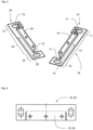
- Fig. 1 and the Fig. 2 show the same embodiment in different representations and are explained together below.
- the carrier lower part 10 and the carrier upper part 20 together form the basic component, which is intended to be attached to the substructure, in particular to an external wall of a building.
- an external thermal separating layer 80 is arranged on the carrier lower part 10, which lies flat on the substructure as intended.
- the two carrier parts 10, 20 are firmly connected to one another by means of the coupling bolt arrangement 50, which in the exemplary embodiment consists of three coupling bolts 51.
- the coupling bolts 51 are designed as rivets in the exemplary embodiment.
- the coupling bolts 51 lead through the respective upper part flange bore 62, then through a hole in the second thermal separation layer 42 of the inner thermal separation layer pair 40, then through the respective sword bore 63 of the sword coupling section 31, further through a hole in the first thermal separation layer 41 of the inner thermal separation layer pair 40 and finally through the respective lower part flange bore 61.
- the second thermal separation layer 42 is fixed flat between the upper part flange 24 and the sword coupling section 31 and the first thermal separation layer 41 is fixed flat between the sword coupling section 31 and the lower part flange 14.
- the heat conduction between the support parts 10, 20, which are already thermally separated from the substructure, to the cantilever blade 30 is further reduced, so that only minimal heat loss is possible through dissipation via the surface or via facade parts mounted on the facade-side mounting section 32.
- Both the support parts 10, 20 and the cantilever blade are made of stainless steel sheet and are therefore corrosion-resistant and have comparatively low heat conductivity.
- the outer thermal separating layer 80 and the inner thermal separating layers 41, 42 are made of foamed PVC in the exemplary embodiment.
- Fig. 3 and Fig. 4 show further details of the support parts 10, 20.
- Both support parts are designed in the same way in this embodiment.
- the support lower part 10 has the lower part middle section 13 and then the first sub-dividing end section 11 and the second sub-dividing end section 12.
- the support upper part 20 has the upper part middle section 23 and then the first upper part end section 21 and the second upper part end section 22.
- the first upper part end section 21 lies on the first sub-dividing end section 11 and the second upper part end section 22 lies on the second lower end section 12, so that the upper and lower fastening holes 71, 72, which are designed as elongated holes in this embodiment, are aligned and can each accommodate a fastening screw for insertion into the substructure.
- the lower part flange 14 protrudes orthogonally from the common lower part base plane 15 and in the carrier upper part 20, the upper part flange 24 protrudes orthogonally from the common upper part base plane 25.
- the outer thermal separation layer 80 is arranged on the lower part base plane underside 16.
- both support parts 10, 20 are made as metal plates, in which after making two lateral incisions in the middle part, an upstand is created for producing the respective flange 14, 24.
- Fig. 4 shows the metal plates in a top view before edging.
- Fig. 5 a modified embodiment in which the cantilever blade 30 has a heat conduction-reducing cross-sectional recess 33 formed by two round recesses.
- the round design advantageously avoids notch stresses and the load-bearing capacity is only insignificantly reduced in relation to the considerable reduction in heat conduction.
- the cross-sectional recess 33 reduces the total cross-section in this section - shown by the dashed line - by reduced by more than 50%.
- the cross-sectional recess 33 is also arranged in the immediate vicinity of the sword coupling section 31; the cantilever sword is thus additionally supported in the section of the cross-sectional recess by the coupled support parts and buckling is counteracted.
Landscapes
- Engineering & Computer Science (AREA)
- Architecture (AREA)
- Civil Engineering (AREA)
- Structural Engineering (AREA)
- Building Environments (AREA)
- Vehicle Step Arrangements And Article Storage (AREA)
- Finishing Walls (AREA)
- Load-Bearing And Curtain Walls (AREA)
Applications Claiming Priority (1)
| Application Number | Priority Date | Filing Date | Title |
|---|---|---|---|
| DE202023001855 | 2023-08-31 |
Publications (3)
| Publication Number | Publication Date |
|---|---|
| EP4517024A2 true EP4517024A2 (fr) | 2025-03-05 |
| EP4517024A3 EP4517024A3 (fr) | 2025-03-12 |
| EP4517024B1 EP4517024B1 (fr) | 2026-05-06 |
Family
ID=92593304
Family Applications (1)
| Application Number | Title | Priority Date | Filing Date |
|---|---|---|---|
| EP24000100.8A Active EP4517024B1 (fr) | 2023-08-31 | 2024-08-26 | Console de sous-construction de façade |
Country Status (2)
| Country | Link |
|---|---|
| EP (1) | EP4517024B1 (fr) |
| DE (1) | DE102024002738A1 (fr) |
Citations (1)
| Publication number | Priority date | Publication date | Assignee | Title |
|---|---|---|---|---|
| DE202012001462U1 (de) | 2012-02-15 | 2012-03-14 | Deutsche Kahneisen Gesellschaft Mbh | Bauwerk mit Wärmedämmelementen |
Family Cites Families (3)
| Publication number | Priority date | Publication date | Assignee | Title |
|---|---|---|---|---|
| DE29703013U1 (de) * | 1997-02-20 | 1997-04-03 | BWM Dübel- u. Montagetechnik GmbH, 70771 Leinfelden-Echterdingen | Wandhalter für Tragvorrichtungen von Wand- oder Deckenverkleidungen |
| US20150308098A1 (en) * | 2014-02-24 | 2015-10-29 | Av_New S.R.L. | Thermal break bracket for a support frame of covering elements |
| EP3222794B1 (fr) * | 2016-03-24 | 2019-02-27 | STO SE & Co. KGaA | Dispositif de retenue destine a appliquer des elements de revetement de plafond ou mural en forme de plaques sur un fond cote construction et procede de fabrication du dispositif de retenue |
-
2024
- 2024-08-23 DE DE102024002738.6A patent/DE102024002738A1/de active Pending
- 2024-08-26 EP EP24000100.8A patent/EP4517024B1/fr active Active
Patent Citations (1)
| Publication number | Priority date | Publication date | Assignee | Title |
|---|---|---|---|---|
| DE202012001462U1 (de) | 2012-02-15 | 2012-03-14 | Deutsche Kahneisen Gesellschaft Mbh | Bauwerk mit Wärmedämmelementen |
Also Published As
| Publication number | Publication date |
|---|---|
| EP4517024B1 (fr) | 2026-05-06 |
| EP4517024A3 (fr) | 2025-03-12 |
| DE102024002738A1 (de) | 2025-03-06 |
Similar Documents
| Publication | Publication Date | Title |
|---|---|---|
| EP1201940B1 (fr) | Profil d'écrou pour rail | |
| EP3914799B1 (fr) | Agencement de profilés | |
| EP3239431B2 (fr) | Console d'ancrage pour fixer un revetement sur un mur porteur et tole d'une console d'ancrage | |
| EP3414114B1 (fr) | Ensemble essieu | |
| EP1500767B1 (fr) | Dispositif de support et de fixation d'encadrements pour portes ou fenêtres à la périphérie d'une ouverture de paroi | |
| DE19720863C5 (de) | Heiz- und/oder Kühlelement für Wände, Decken und/oder Fußböden von Gebäuden | |
| EP1866492B1 (fr) | Profile en c et cloison de séparation à profile en c | |
| EP0235493B1 (fr) | Profilé composite thermiquement isolant | |
| EP4517024B1 (fr) | Console de sous-construction de façade | |
| DE3603221C2 (fr) | ||
| EP4274939B1 (fr) | Supports muraux pour une façade suspendue ventilée et une façade suspendue ventilée | |
| EP2157270B1 (fr) | Profilé calorifuge pour constructions ignifuges et profilé composite pour façades, fenêtres et portes | |
| DE19627342B4 (de) | Bauelement zur Wärmedämmung | |
| EP3144448A1 (fr) | Plaque de montage destinee a fixer un composant sur un mur | |
| EP0810334A1 (fr) | Elément de construction pour isolation thermique | |
| EP2532799A1 (fr) | Support métallique et son utilisation | |
| AT407419B (de) | Sonnenschutzanlage | |
| EP4050172A1 (fr) | Connecteur de profilé et sous-structure pour éléments de mur ou de toit | |
| EP1602836A1 (fr) | Nervure raidisseuse pour bois massif | |
| WO2022043156A1 (fr) | Système de retenue composé d'un élément d'assemblage d'arbalétriers et d'un support latéral pour maintenir des conduits verticaux, comme des cheminées | |
| DE202020000211U1 (de) | Distanzstück und System zum dauerhaften Befestigen eines Bauteils an wenigstens einem Befestigungspunkt | |
| DE19831026A1 (de) | Tragende Seilkonstruktion | |
| WO2004016874A1 (fr) | Dalle en beton composite et ancre de maintien servant a assembler deux dalles en beton | |
| DE202022103708U1 (de) | Einhängeelement für Ankerplatte eines Seitenunfallschutzes, Ankerplatte für Seitenunfallschutz sowie System aus Ankerplatte und Einhängeelement | |
| DE10164750B4 (de) | Befestigungselement für ein Dämmstoffelement |
Legal Events
| Date | Code | Title | Description |
|---|---|---|---|
| PUAI | Public reference made under article 153(3) epc to a published international application that has entered the european phase |
Free format text: ORIGINAL CODE: 0009012 |
|
| STAA | Information on the status of an ep patent application or granted ep patent |
Free format text: STATUS: THE APPLICATION HAS BEEN PUBLISHED |
|
| PUAL | Search report despatched |
Free format text: ORIGINAL CODE: 0009013 |
|
| AK | Designated contracting states |
Kind code of ref document: A2 Designated state(s): AL AT BE BG CH CY CZ DE DK EE ES FI FR GB GR HR HU IE IS IT LI LT LU LV MC ME MK MT NL NO PL PT RO RS SE SI SK SM TR |
|
| AK | Designated contracting states |
Kind code of ref document: A3 Designated state(s): AL AT BE BG CH CY CZ DE DK EE ES FI FR GB GR HR HU IE IS IT LI LT LU LV MC ME MK MT NL NO PL PT RO RS SE SI SK SM TR |
|
| RIC1 | Information provided on ipc code assigned before grant |
Ipc: E04F 13/08 20060101AFI20250206BHEP |
|
| STAA | Information on the status of an ep patent application or granted ep patent |
Free format text: STATUS: REQUEST FOR EXAMINATION WAS MADE |
|
| 17P | Request for examination filed |
Effective date: 20250912 |
|
| GRAP | Despatch of communication of intention to grant a patent |
Free format text: ORIGINAL CODE: EPIDOSNIGR1 |
|
| STAA | Information on the status of an ep patent application or granted ep patent |
Free format text: STATUS: GRANT OF PATENT IS INTENDED |
|
| INTG | Intention to grant announced |
Effective date: 20260130 |
|
| GRAS | Grant fee paid |
Free format text: ORIGINAL CODE: EPIDOSNIGR3 |
|
| GRAA | (expected) grant |
Free format text: ORIGINAL CODE: 0009210 |
|
| STAA | Information on the status of an ep patent application or granted ep patent |
Free format text: STATUS: THE PATENT HAS BEEN GRANTED |