EP4517189A1 - Plaque de cuisson - Google Patents
Plaque de cuisson Download PDFInfo
- Publication number
- EP4517189A1 EP4517189A1 EP23193737.6A EP23193737A EP4517189A1 EP 4517189 A1 EP4517189 A1 EP 4517189A1 EP 23193737 A EP23193737 A EP 23193737A EP 4517189 A1 EP4517189 A1 EP 4517189A1
- Authority
- EP
- European Patent Office
- Prior art keywords
- frame part
- cooking hob
- area
- worktop
- cut
- Prior art date
- Legal status (The legal status is an assumption and is not a legal conclusion. Google has not performed a legal analysis and makes no representation as to the accuracy of the status listed.)
- Pending
Links
Images
Classifications
-
- F—MECHANICAL ENGINEERING; LIGHTING; HEATING; WEAPONS; BLASTING
- F24—HEATING; RANGES; VENTILATING
- F24C—DOMESTIC STOVES OR RANGES ; DETAILS OF DOMESTIC STOVES OR RANGES, OF GENERAL APPLICATION
- F24C15/00—Details
- F24C15/10—Tops, e.g. hot plates; Rings
- F24C15/108—Mounting of hot plate on worktop
Definitions
- the present invention relates to a cooking hob configured to be mounted in a cut-out of a worktop according to claim 1 or claim 2.
- cooking appliances are used for the preparation of food in or on specific food treatment areas in order to prepare dishes or meals.
- Cooking processes are particularly performed on cooking hobs, which comprise cooking zones for placement of cookware receiving the food to be cooked.
- the cooking zones are generally arranged on a cooktop, which forms an upper wall of the cooking hob.
- the cooktop is usually a glass ceramic cooktop.
- Such glass ceramic cooktops can be provided as a frameless plate, which overlaps with a peripheral zone a cut-out area of a kitchen worktop, in which the built-in hob is installed.
- EP 1 970 632 A2 proposes to border at least lateral edges, which lead away from a front edge of the glass ceramic cooktop, particularly also a rear edge of the cooktop, by frame elements, each comprising vertically rising bar, which may end in vertical direction at the level of or below a top edge of an adjacent front face of the cooktop.
- a cooking hob configured to be mounted in a cut-out of a worktop, i. e. a cooking hob according to those features of claim 1 or of claim 2, which are generally known, by the features of claim 1 characterizing the present invention.
- a cooking hob comprises a cooktop with at least one cooking zone.
- the cooktop particularly comprises a glass ceramic plate, which material is nowadays commonly used specifically for cooking hobs that are operated by electricity.
- the cooking hob is configured to be installed in a cut-out of a worktop, more specifically in a kitchen worktop. The installation is performed or performable in a way that at least one outer edge of the cooking hob is allocated or allocatable to a related edge of the cut-out of the worktop.
- the at least one outer edge of the cooking hob, more specifically at least one outer edge of the glass ceramic plate comprises or is configured to receive a frame part.
- the frame part is fastened or configured to be fastened to a surface of the cooking hob, more specifically to a surface of the glass ceramic plate of the cooktop.
- Said frame part is or comprises a frame bar, which comprises a first area or portion and a second area or portion, which first and second areas or portions are in a side-by-side and/or parallel arrangement. Further, the second area or portion is arranged farther away from a centre of the cooking hob than the first area or portion.
- the first area or portion comprises fastening means for fastening the frame part to the outer edge of the cooking hob by way of a suspended fastening of the cooking hob. More specifically, the frame part is configured to be fastened to the outer edge of the glass ceramic plate.
- the term "suspended fastening” may be understood as the cooking hob, or more specifically the glass ceramic plate, being supported by the frame part in a hanging condition. Said fastening means preferably act on an upper side of the cooking hob, which is more specifically an upper side of the class ceramic plate.
- the second area or portion comprises a support area at a bottom side of the frame part, which is configured to at least partially rest on the cut-out edge or an area close to the cut-out edge of the worktop.
- side-by-side arrangement as herein disclosed may mean that first and second areas or portions are arranged besides each other, with or without having a shared border.
- a cooking hob comprises a cooktop with at least one cooking zone.
- the cooktop particularly comprises a glass ceramic plate.
- the cooking hob according to the second aspect is particularly a specific embodiment of the cooking hob as previously disclosed, i.e. a specific embodiment of the cooking hob according to the first aspect of the present invention.
- the cooking hob according to the second aspect is also configured to be installed in a cut-out of a worktop, which is more specifically a kitchen worktop. The installation is performed or performable in a way that at least one outer edge of the cooking hob is allocated or allocatable to a related cut-out edge of the worktop.
- the at least one outer edge of the cooking hob comprises or is configured to receive a frame part, which is fastened or configured to be fastened to a surface of the cooking hob, more specifically to a surface of the glass ceramic plate of the cooktop.
- the frame part is configured to or designed in a way as to arrange an upper surface of the cooking hob, more specifically an upper surface of the glass ceramic plate, horizontally aligned with an upper surface of the worktop.
- horizontally aligned as herein disclosed, may mean that the upper surfaces of the cooking hob, more specifically of the glass ceramic plate, on the one hand, and of the worktop, on the other hand, are at the same horizontal level.
- the frame part comprises a first area or portion, which comprises fastening means for fastening the frame part to the outer edge of the cooking hob, more specifically to the outer edge of the glass ceramic plate.
- the frame part comprises a second area or portion, which comprises a support area at a bottom side of the frame part. Said support area is configured to at least partially rest on the cut-out edge or an area close to the cut-out edge of the worktop.
- the first and second areas or portions are in a side-by-side and/or parallel arrangement and the second area or portion is arranged or farther away from a centre of the cooking hob than the first area or portion.
- the cooking hob according to the second aspect of the present invention is characterized by providing an impression of an overall even working area in a kitchen environment, when installed in a kitchen worktop, as a result of the horizontal alignment of upper surfaces of the worktop and the cooking hob, or specifically of the glass ceramic plate.
- the cooking hob comprises a plurality of outer edges, more specifically the cooking hob is of rectangular shape and comprises four outer edges, each one thereof being allocated or allocatable to a related section of a circumferential cut-out edge of the worktop.
- This characteristic feature may be valid for either one of the cooking hobs according to first or second aspects as herein disclosed.
- the frame part comprises a flat upper surface and/or a flat lower surface.
- the frame part is preferably essentially flat over at least nearly its entire width.
- Such a flat design further supports a smooth transition area between cooking hob, or glass ceramic plate, respectively, and the upper surface of the worktop.
- the frame part may be or may comprise a frame bar or strip, in particular a trim strip.
- This frame bar or strip comprises at least one first contact surface or zone, which abuts upon an upper surface of the glass ceramic plate, and at least one second contact surface or zone, which is configured to abut upon the upper surface of the worktop.
- the at least one second surface or zone may also rest on and may be supported by the worktop.
- the first and second contact surfaces or zones are preferably in horizontal alignment. That way, a horizontally aligned arrangement of the upper surfaces of the cooking hob and the worktop may be established as well.
- the frame part more specifically the frame bar or strip, comprises or forms a carrying structure extending in horizontal direction, which is designed with a thickness, specifically extending in vertical direction, that is at least slightly higher than a minimum thickness necessary for guaranteeing stability of the frame part during all occurring load situations, in particular breaking strength, shearing strength, tensile strength, and elasticity limit.
- the defined thickness for the frame part is between 0.5 and 1.0 mmm, preferably around 0.6 mm.
- the cooking hob according to the present invention is characterized by a frame part working with reduced width and height. Consequently, more freedom in design is available to the designers of the cooking hob as the design for the frame part is selectable from a broader range. More specifically, designs with smooth appearance are selectable as a result of the present invention. Said increased design selection may particularly provide the possibility to differentiate individual models of a product range from one another. The product designers may define different models with different widths and/or thicknesses of the frame part. Additionally, or alternatively, a frame of one and the same hob may be equipped with different widths and/or thicknesses at different edges of the frame part.
- the frame part comprises a sharp cut design or a small radius at at least one upper outer longitudinal frame part edge, preferably comprising a sharp cut design or a small radius at both upper outer longitudinal frame part edges of a particularly elongated frame part. Provision of a sharp edge design at the upper outer longitudinal edges, which are facing the observer's view, provide a particular design impression of the mounted cooking hob. Such a design feature of a flat frame part with sharp edges may also lead to an easy-to-clean solution.
- the frame part is fastened or configured to be fastened on the upper surface of the glass ceramic plate of the cooktop.
- the fastening is formed by any bonded joint or by an application of a double-sided adhesive tape.
- a particularly preferred solution relies on a glue material and process, which for example includes an application of a liquid silicone glue.
- the fastening may be performed in a contiguous or intermittent manner. While an intermittent fastening may save fastening material, a contiguous fastening may be favourable in terms of a complete sealing against liquids spilled on the cooking surface of the cooking hob, more specifically spilled on the glass ceramic plate.
- a gasket means is arranged at the bottom side of the second area or portion of the frame part, in particular at the support area at the bottom side of the frame part.
- the gasket means may be configured to provide a sealing between the bottom side of the frame part and the worktop.
- the gasket means preferably comprises at least one of a liquid applied foam, a tape with foam or rubber, and/or any other sealing material. With such a gasket means, a liquid entry into the cut-out of the worktop is prevented.
- the gasket means may be a separated part, which may be arrangeable between the worktop and the frame part, or configured to be sticked on the worktop surface.
- a particularly preferred frame part is characterized in that during the manufacturing process it receives a glue material on its first area or portion in order to glue the frame part at the outer edge of the cooking hob, particularly at the outer edge of the glass ceramic plate. Further, the frame part may be provided with liquid applied foam adapted to provide said sealing of the frame part against the worktop surface.
- the gasket means is compressible, which is favourable with respect to a secure sealing, even if both or anyone of the frame part or worktop surfaces may be uneven.
- the gasket means has a Shore hardness allowing a compression under the weight of the cooking hob to that extent that a bottom side of the frame part, in particular the second contact surface or zone and/or the lateral surface of the related folded or bent longitudinal edge, rests upon or is configured to rest upon the cut-out edge of the worktop or an area close to the cut-out edge of the worktop without any reduction or limitation of the sealing effect.
- the frame part can be a stamped flat part, which may be designed with a rectangular cross-sectional surface.
- a stamped flat frame bar particularly provides access, in particular visual access, to the glue or gasket material arranged between frame part and cooking hob and between frame part and worktop, respectively.
- a stamping process executed from the upper side of the frame part which is that side facing the observer, establishes a slightly rounded upper edge of the sheet material, what is favourable in terms of preventing injuries that might occur at any sharp-edged frame part.
- a stamping process may be only one possible manufacturing process for the frame part, in fact, other metal severing processes may be used for producing this part, such as laser cutting or sawing or the like.
- the frame part more specifically the frame bar or strip, comprises at least one folded or bent longitudinal edge, which extends downwards from the lower surface of the frame part.
- Said extension is particularly realized with an extension value, which at least corresponds to a technically necessary layer thickness for glue and/or gasket material. More specifically, in order to completely hide the gluing and gasket material, on the one hand, by fully securing the gluing and sealing functionalities, on the other hand, the extension downwards of the bent edges may be selected accordingly.
- a minimum height of the frame is specifically defined by a hiding of the necessary glue thickness for glass ceramic plate connection and a coverage of the gasket material for sealing towards the worktop.
- the thickness of the glue material may depend on its sticking strength, which itself may be dependent on the selected material.
- said extension is in the range of between 0.2 and 1.5 mm, preferably in the range of between 0.5 and 1.0 mm, more preferably around 0.8 mm.
- the frame part comprises folded or bent opposite longitudinal edges, which are particularly arranged in parallel.
- the frame part more specifically the frame bar or strip, comprises folded or bent opposite longitudinal edges, preferably by forming a symmetrically identical frame part.
- at least one of the lateral surfaces, or a related border of such a lateral surface, of the longitudinal edges at least partially touches or is configured to touch at least one of the glass ceramic plate and the worktop.
- the at least one folded or bent edge is angled towards the horizontal by between 15 and 90 degrees, preferably by between 30 and 60 degrees, more preferably around 45 degrees.
- the frame part in particular the frame bar or strip, comprises an embossed groove or channel for providing an improved stiffness at and flatness of the frame part and/or for providing space for glue material.
- Said embossed groove or channel is particularly favourable for performing an automized gluing process.
- a particularly preferred solution of the present invention is characterized by a cooking hob, which provides for a frame part, more specifically the frame bar or strip, is manufactured by a stamping and/or a bending and/or a deep drawing process.
- the frame part is made of a metallic, e. g. of aluminium or stainless steel, material.
- the cooking hob particularly when being of a rectangular shape, may circumferentially be equipped with the frame part according to the present invention.
- the frame part may be a composition of a plurality of individual frame parts, more specifically of four individual frame parts, or it may be designed in one piece.
- Such surrounding entire frame, designed in one piece, is preferably the result of a combination of a stamping, a bending and a deep drawing process.
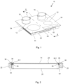
- Fig. 1 illustrates schematically a cooking hob 10, which is designed to be installed in a cut-out of a kitchen worktop 22.
- the cooking hob 10 comprises four cooking zones 12 indicated by circles imprinted on a cooktop 14 of the cooking hob 12.
- Cookware is placeable on the cooking zones 12 for performing the cooking process, indicated by pots 16 in the figures.
- the cooktop 14 comprises a cooktop plate, which is made of a glass ceramic material and the embodiment illustrated by Fig. 1 is an example of a frameless cooktop 14, i. e. the glass ceramic cooktop plate 24 is not bordered by any frame part, e. g. any metallic frame.
- the cooking zones 12 are heated by means of heating elements (not shown) arranged underneath and close to the cooktop 14 or the glass ceramic plate, respectively.
- Said heating elements may be of electric nature as indicated in the figures, but other heating systems like gas cooking elements are considerable as well.
- One preferred cooking solution provides for induction cooking and, respectively, the heating elements are induction coils.
- the cooking hob 10, as illustrated in Fig. 1 is operable by a user by means of a user interface 18, which is arranged at a front edge of the cooktop 14.
- a user interface 18 may be laterally arranged as illustrated in Fig. 1 or centrally arranged (not shown).
- the user interface 18 may include any types of control units for providing control inputs to a control unit of the cooking hob 10.
- the present example is characterized by touch control elements and the control inputs are provided by the user on a touch surface of the user interface 18.
- FIG. 1 further illustrates a bottom part of the cooking hob 10, represented by a hob casing 20, which includes the electrical and electronic components of the cooking hob 10 and which is fastened on the bottom side of the glass ceramic plate 24, more specifically fastened by means of brackets 26, which are glued to the bottom side of the glass ceramic plate 24 by means of a glue bead 28.
- a hob casing 20 which includes the electrical and electronic components of the cooking hob 10 and which is fastened on the bottom side of the glass ceramic plate 24, more specifically fastened by means of brackets 26, which are glued to the bottom side of the glass ceramic plate 24 by means of a glue bead 28.
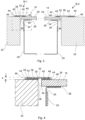
- FIG. 2 illustrates a pure presentation of the cooktop 14 including the glass ceramic plate 24 as well as the attached casing 20 connected to the bottom side of the glass ceramic plate 24 by brackets 26, as will be more illustrated further down below with reference to Figs. 3 and 4 .
- Fig. 2 also provides a general view of the installation of the cooking hob 10 in the cut-out 30 of a kitchen worktop 22
- the cut-out 30 does not only take the casing 20 of the cooking hob 10 up with the glass ceramic plate 24 resting on cut-out edge 36 of the kitchen worktop 22, or more precisely resting on a strip at the cut-out edge 36, which has the effect of an elevated upper surface of the glass ceramic plate 24 compared to the upper surface of the worktop 22.
- the cooking hob 10 is included entirely, i. e. including the glass ceramic plate 24, in the cut-out 30, with the effect of the upper surfaces of kitchen worktop 22 and glass ceramic plate 24 being arranged at the same level.
- the installation of the cooking hob 10 in the cut-out 30 is performed by means of a frame part 38, which is designed as a flat frame bar that may essentially be an elongated metal strip covering the transition zone between glass ceramic plate 24 and worktop 22.
- Said frame part 38 is arranged at all four borders of the rectangular glass ceramic plate 24, so that the entire frame is formed by a rectangular frame element being an arrangement of four said frame parts 38.
- This arrangement may be of a one-part solution or a structure of four individual frame parts 38 forming said rectangular frame element circumferentially surrounding the cooking hob 10, more specifically the glass ceramic plate 24.
- the frame part 38 also covers a circumferential gap 32 between glass ceramic plate edge 34 and worktop edge, i. e. cut-out edge 36, which gap 32 is constructionally provided in order to compensate tolerances for the installation process.
- the flat frame bar 38 has a thickness, which, on the one hand, is low enough in order to provide for a non-obtrusive appearance of the entire cooking hob installation, and which, on the other hand, is high enough in order to carry the cooking hob 10 together with any load thereon, e. g. filled pots 16, without any plastic deformations or even breakages of the frame part 38.
- the frame part 38 operates as carrying element for the cooking hob 10 inside of the cut-out 36 of the worktop 22 by way of a suspended fastening of the cooking hob 10 at that side of the fastening element 38, which is allocated to the glass ceramic plate 24.
- the suspended fastening is performed by means of a silicon glue 40, more specifically by a liquid glue bead applied on the frame part 38 before attaching it to the glass ceramic plate 24 during the manufacturing process. After fastening the silicon glue 40 is arranged between bottom side of the frame part 38 and upper side of the glass ceramic plate 24.
- This structure of cooking hob 10 and fastened frame part 38 is inserted or insertable in the cut-out 30 of the worktop 22, wherein that side of the fastening element 38, which is allocated to the worktop 22 covers the cut-out edge 36 of the worktop 22 at all sides of the cooking hob 10, so that an all-sided support of the entire cooking hob 10 on the circumferential cut-out edge 36 is realized.
- the side of the fastening element 38, which is allocated to the worktop 22 rests on the cut-out edge 36 by intermediate arrangement of a foam gasket layer 42 performing an all-sided sealing of the frame part 38 against the worktop 22.
- Silicon glue layer 40 and foam gasket layer 42 are designed in a way supporting the effect of the upper surfaces of kitchen worktop 22 and glass ceramic plate 24 being arranged at the same level.
- Fig. 4 illustrates that the frame part 38 comprises at its lateral sides folded or bent longitudinal edges 46, which extend downwards from the bottom surface of the frame part 38 towards the upper surfaces of the glass ceramic plate 24 and the worktop 22, respectively. More specifically, the outer edges of the folded or bent longitudinal edges 46 touch or rest on said upper surfaces in a way, that neither the silicone glue 40 nor the foam gasket is visible but laterally covered by the related folded or bent longitudinal edge 46. Moreover, the folded or bent longitudinal edges 46 may also be designed in a way supporting the effect of the upper surfaces of kitchen worktop 22 and glass ceramic plate 24 being arranged at the same level. The alignment of the folded or bent longitudinal edges 46 may be in vertical direction, or, as illustrated in Fig. 4 , inclined toward the upper surfaces of glass ceramic plate 24 and worktop 22, particularly by including an angle of around 45 degrees.
- embossed grooves 48 are provided on the bottom side of the frame part 38 at the areas of bending, in particular for performing an automized gluing process.
- the frame part 38 is specifically designed with using a flat metal strip of around 0.6 ... 0.8 mm thickness, which is bent at its lateral edges 46 by providing a frame part 38, which results in an elevation e of around 1.4 mm of the frame part 38 over the level of upper surfaces of glass ceramic plate 24 and worktop 22.
- a total width of around 16 mm of the frame part 38 may be provided, which is split up by an overlap of around 6 mm at the glass ceramic plate side, an overlap of around 8 mm at the worktop side and an intermediate section of around 2 mm for covering the gap 32.
- Figs. 3 and 4 further provide a more detailed illustration of the previously indicated connection of the hob casing 20 to the bottom side of the glass ceramic plate 24.
- an angled bracket 26 is fastened with its horizontal arm to the glass ceramic plate 24 by means of glue joint 28.
- the vertical arm of the bracket 26 forms a mechanical coupling for the vertical side walls of the hob casing 20, wherein said coupling may be executable by fastening means, e. g. screws.
- a cooking hob 10 with specific dimensions and a specific number of cooking zones is presented by Figs. 1 to 4
- the herein described setup of the cooking hob 10 may be applicable to all usual sizes of cooking hobs 10 and comprising all usual numbers of cooking zones.
- the embodiment according to Figs. 1 to 4 forms only one representative of a plurality of differently designed cooking hobs 10.
- the illustrated cooking hob 10 is one member of a cooking hob product range manufactured on an assembly line, and other members of the product range may be equipped with other frame part 38 particularly with different frame part widths, i. e. not illustrated by the attached figures.
Landscapes
- Engineering & Computer Science (AREA)
- Chemical & Material Sciences (AREA)
- Combustion & Propulsion (AREA)
- Mechanical Engineering (AREA)
- General Engineering & Computer Science (AREA)
- Induction Heating Cooking Devices (AREA)
- Electric Stoves And Ranges (AREA)
Priority Applications (3)
| Application Number | Priority Date | Filing Date | Title |
|---|---|---|---|
| EP23193737.6A EP4517189A1 (fr) | 2023-08-28 | 2023-08-28 | Plaque de cuisson |
| CN202480054903.XA CN121752848A (zh) | 2023-08-28 | 2024-08-05 | 烹饪灶具 |
| PCT/EP2024/072181 WO2025045524A1 (fr) | 2023-08-28 | 2024-08-05 | Table de cuisson |
Applications Claiming Priority (1)
| Application Number | Priority Date | Filing Date | Title |
|---|---|---|---|
| EP23193737.6A EP4517189A1 (fr) | 2023-08-28 | 2023-08-28 | Plaque de cuisson |
Publications (1)
| Publication Number | Publication Date |
|---|---|
| EP4517189A1 true EP4517189A1 (fr) | 2025-03-05 |
Family
ID=87847794
Family Applications (1)
| Application Number | Title | Priority Date | Filing Date |
|---|---|---|---|
| EP23193737.6A Pending EP4517189A1 (fr) | 2023-08-28 | 2023-08-28 | Plaque de cuisson |
Country Status (3)
| Country | Link |
|---|---|
| EP (1) | EP4517189A1 (fr) |
| CN (1) | CN121752848A (fr) |
| WO (1) | WO2025045524A1 (fr) |
Citations (9)
| Publication number | Priority date | Publication date | Assignee | Title |
|---|---|---|---|---|
| GB2019556A (en) * | 1978-04-21 | 1979-10-31 | Zeiss Stiftung | Vitreous ceramic cooker hob plate assembly |
| EP0567779A1 (fr) * | 1992-03-27 | 1993-11-03 | Schott Glaswerke | Plaque de cuisson |
| EP0643270A2 (fr) * | 1993-09-04 | 1995-03-15 | Schott Glaswerke | Dispositif de support de plaques de cuisson encastrables |
| US5571434A (en) * | 1994-06-29 | 1996-11-05 | Whirlpool Corporation | Cooktop stamping having means for attaching heating elements and an integral trim ring |
| US5893359A (en) * | 1994-09-29 | 1999-04-13 | Schott Glaswerke | Arrangement for assembling and mounting a built-in cooktop |
| EP0936411A2 (fr) * | 1998-02-12 | 1999-08-18 | Balay S.A. | Système de montage pour plaques de cuisson en verre-céramique |
| DE102006037241A1 (de) * | 2005-08-16 | 2007-04-12 | BSH Bosch und Siemens Hausgeräte GmbH | Kochgerät |
| EP1970632A2 (fr) | 2007-03-16 | 2008-09-17 | BSH Bosch und Siemens Hausgeräte GmbH | Champ de cuisson |
| EP2110608A1 (fr) * | 2008-04-18 | 2009-10-21 | Electrolux Home Products Corporation N.V. | Plaque de cuisson et cadre stylique pour plaque de cuisson |
-
2023
- 2023-08-28 EP EP23193737.6A patent/EP4517189A1/fr active Pending
-
2024
- 2024-08-05 CN CN202480054903.XA patent/CN121752848A/zh active Pending
- 2024-08-05 WO PCT/EP2024/072181 patent/WO2025045524A1/fr not_active Ceased
Patent Citations (9)
| Publication number | Priority date | Publication date | Assignee | Title |
|---|---|---|---|---|
| GB2019556A (en) * | 1978-04-21 | 1979-10-31 | Zeiss Stiftung | Vitreous ceramic cooker hob plate assembly |
| EP0567779A1 (fr) * | 1992-03-27 | 1993-11-03 | Schott Glaswerke | Plaque de cuisson |
| EP0643270A2 (fr) * | 1993-09-04 | 1995-03-15 | Schott Glaswerke | Dispositif de support de plaques de cuisson encastrables |
| US5571434A (en) * | 1994-06-29 | 1996-11-05 | Whirlpool Corporation | Cooktop stamping having means for attaching heating elements and an integral trim ring |
| US5893359A (en) * | 1994-09-29 | 1999-04-13 | Schott Glaswerke | Arrangement for assembling and mounting a built-in cooktop |
| EP0936411A2 (fr) * | 1998-02-12 | 1999-08-18 | Balay S.A. | Système de montage pour plaques de cuisson en verre-céramique |
| DE102006037241A1 (de) * | 2005-08-16 | 2007-04-12 | BSH Bosch und Siemens Hausgeräte GmbH | Kochgerät |
| EP1970632A2 (fr) | 2007-03-16 | 2008-09-17 | BSH Bosch und Siemens Hausgeräte GmbH | Champ de cuisson |
| EP2110608A1 (fr) * | 2008-04-18 | 2009-10-21 | Electrolux Home Products Corporation N.V. | Plaque de cuisson et cadre stylique pour plaque de cuisson |
Also Published As
| Publication number | Publication date |
|---|---|
| WO2025045524A1 (fr) | 2025-03-06 |
| CN121752848A (zh) | 2026-03-27 |
Similar Documents
| Publication | Publication Date | Title |
|---|---|---|
| US9521708B2 (en) | Oven range appliance | |
| KR101058688B1 (ko) | 내장형 가열 조리기 및 그 가열 조리기가 조립되는 주방조리대 | |
| US6281480B1 (en) | Installation strip for a cooktop | |
| US7640930B2 (en) | Air-inlet assembly for a gas cooking appliance | |
| US9732963B2 (en) | Appliance control panel assembly | |
| US6207934B1 (en) | Cook top with installation frame formed by bending | |
| US20120318256A1 (en) | Large capacity griddle over high btu burner | |
| US5893359A (en) | Arrangement for assembling and mounting a built-in cooktop | |
| JP2012022775A (ja) | 加熱調理器 | |
| WO2025045524A1 (fr) | Table de cuisson | |
| JP2003045626A (ja) | 窪み湾曲した加熱面を有するガラスセラミックボウルを備えた調理台 | |
| EP4279820A1 (fr) | Plaque de cuisson | |
| JP4168900B2 (ja) | 調理器 | |
| EP2110608B1 (fr) | Plaque de cuisson avec cadre stylique | |
| EP3351859B1 (fr) | Plaque de cuisson | |
| CN219775822U (zh) | 炉具 | |
| EP2378207B1 (fr) | Agencement de cuisine | |
| EP3676536B1 (fr) | Table de cuisson, panneau de table de cuisson et son procédé de fabrication | |
| JP3891264B2 (ja) | ガスコンロ | |
| EP3398480A1 (fr) | Surface de cuisson | |
| EP2065649B1 (fr) | Appareil de cuisson, en particulier appareil de cuisson domestique | |
| US9267693B2 (en) | Decorative frame for a domestic appliance, domestic appliance comprising such a decorative frame, and method for producing a decorative frame | |
| CN211432256U (zh) | 自动炒菜机 | |
| KR100700881B1 (ko) | 상면 조작형 곤로 | |
| CN107917444A (zh) | 灶具 |
Legal Events
| Date | Code | Title | Description |
|---|---|---|---|
| PUAI | Public reference made under article 153(3) epc to a published international application that has entered the european phase |
Free format text: ORIGINAL CODE: 0009012 |
|
| STAA | Information on the status of an ep patent application or granted ep patent |
Free format text: STATUS: THE APPLICATION HAS BEEN PUBLISHED |
|
| AK | Designated contracting states |
Kind code of ref document: A1 Designated state(s): AL AT BE BG CH CY CZ DE DK EE ES FI FR GB GR HR HU IE IS IT LI LT LU LV MC ME MK MT NL NO PL PT RO RS SE SI SK SM TR |
|
| STAA | Information on the status of an ep patent application or granted ep patent |
Free format text: STATUS: REQUEST FOR EXAMINATION WAS MADE |
|
| 17P | Request for examination filed |
Effective date: 20250905 |
|
| STAA | Information on the status of an ep patent application or granted ep patent |
Free format text: STATUS: EXAMINATION IS IN PROGRESS |
|
| 17Q | First examination report despatched |
Effective date: 20260630 |