EP4518529A1 - Procédé et appareil permettant de réaliser une communication de liaison latérale dans un système de communication sans fil - Google Patents
Procédé et appareil permettant de réaliser une communication de liaison latérale dans un système de communication sans fil Download PDFInfo
- Publication number
- EP4518529A1 EP4518529A1 EP23796796.3A EP23796796A EP4518529A1 EP 4518529 A1 EP4518529 A1 EP 4518529A1 EP 23796796 A EP23796796 A EP 23796796A EP 4518529 A1 EP4518529 A1 EP 4518529A1
- Authority
- EP
- European Patent Office
- Prior art keywords
- resource
- lbt
- consistent
- triggered
- sets
- Prior art date
- Legal status (The legal status is an assumption and is not a legal conclusion. Google has not performed a legal analysis and makes no representation as to the accuracy of the status listed.)
- Pending
Links
Images



Classifications
-
- H—ELECTRICITY
- H04—ELECTRIC COMMUNICATION TECHNIQUE
- H04W—WIRELESS COMMUNICATION NETWORKS
- H04W24/00—Supervisory, monitoring or testing arrangements
- H04W24/08—Testing, supervising or monitoring using real traffic
-
- H—ELECTRICITY
- H04—ELECTRIC COMMUNICATION TECHNIQUE
- H04W—WIRELESS COMMUNICATION NETWORKS
- H04W72/00—Local resource management
- H04W72/02—Selection of wireless resources by user or terminal
-
- H—ELECTRICITY
- H04—ELECTRIC COMMUNICATION TECHNIQUE
- H04W—WIRELESS COMMUNICATION NETWORKS
- H04W72/00—Local resource management
- H04W72/04—Wireless resource allocation
- H04W72/044—Wireless resource allocation based on the type of the allocated resource
- H04W72/0453—Resources in frequency domain, e.g. a carrier in FDMA
-
- H—ELECTRICITY
- H04—ELECTRIC COMMUNICATION TECHNIQUE
- H04W—WIRELESS COMMUNICATION NETWORKS
- H04W72/00—Local resource management
- H04W72/04—Wireless resource allocation
- H04W72/044—Wireless resource allocation based on the type of the allocated resource
- H04W72/0457—Variable allocation of band or rate
-
- H—ELECTRICITY
- H04—ELECTRIC COMMUNICATION TECHNIQUE
- H04W—WIRELESS COMMUNICATION NETWORKS
- H04W72/00—Local resource management
- H04W72/20—Control channels or signalling for resource management
- H04W72/25—Control channels or signalling for resource management between terminals via a wireless link, e.g. sidelink
-
- H—ELECTRICITY
- H04—ELECTRIC COMMUNICATION TECHNIQUE
- H04W—WIRELESS COMMUNICATION NETWORKS
- H04W72/00—Local resource management
- H04W72/50—Allocation or scheduling criteria for wireless resources
- H04W72/53—Allocation or scheduling criteria for wireless resources based on regulatory allocation policies
-
- H—ELECTRICITY
- H04—ELECTRIC COMMUNICATION TECHNIQUE
- H04W—WIRELESS COMMUNICATION NETWORKS
- H04W74/00—Wireless channel access
- H04W74/08—Non-scheduled access, e.g. ALOHA
- H04W74/0808—Non-scheduled access, e.g. ALOHA using carrier sensing, e.g. carrier sense multiple access [CSMA]
-
- H—ELECTRICITY
- H04—ELECTRIC COMMUNICATION TECHNIQUE
- H04W—WIRELESS COMMUNICATION NETWORKS
- H04W92/00—Interfaces specially adapted for wireless communication networks
- H04W92/16—Interfaces between hierarchically similar devices
- H04W92/18—Interfaces between hierarchically similar devices between terminal devices
Definitions
- the present disclosure relates to a wireless communication system, and more particularly, to a method and device for performing sidelink communication in a wireless communication system.
- the technical problem of the present disclosure is to provide a method and device for performing sidelink communication in a wireless communication system.
- the technical problem of the present disclosure is to provide a method and device for detecting SL LBT in units of SL resource pool or/and RB set.
- the technical problem of the present disclosure is to provide a method and device for triggering an SL resource reselection procedure when a consistent LBT failure is triggered.
- a method performed by a first user equipment (UE) in a wireless communication system may include receiving, from a base station, configuration information related to a plurality of sidelink (SL) resource pools and a plurality of resource block (RB) sets; detecting and triggering a consistent SL LBT (listen before talk) failure for at least one of a first SL resource pool or a first RB set among the plurality of SL resource pools and the plurality of RB sets; and based on the triggered consistent SL LBT failure not being cancelled, triggering SL resource reselection to select a second SL resource pool or a second RB set among the plurality of resource pools and the plurality of RB sets.
- SL LBT listen before talk
- a method performed by a base station in a wireless communication system may include transmitting, to a first user equipment (UE), configuration information related to a plurality of sidelink (SL) resource pools and a plurality of resource block (RB) sets; receiving, from the first UE, a MAC CE related to a consistent SL LBT (listen before talk) failure for at least one of a first SL resource pool or a first RB set among the plurality of SL resource pools and the plurality of RB sets, and based on the triggered consistent SL LBT failure not being cancelled, SL resource reselection for selecting a second SL resource pool or a second RB set from among the plurality of resource pools and the plurality of RB sets may be triggered by the first UE.
- SL LBT listen before talk
- a method and device for performing sidelink communication in a wireless communication system may be provided.
- a method and device for detecting SL LBT in units of SL resource pools or/and RB sets may be provided.
- a method and device for triggering an SL resource reselection procedure when a consistent LBT failure is triggered may be provided.
- a base station/terminal by detecting LBT failure in units of resource pools or RB sets within an SL BWP in a sidelink of an unlicensed band, a base station/terminal can operate resources based on a smaller range of congestion detection.
- a term used in the present disclosure is to describe a specific embodiment, and is not to limit a claim. As used in a described and attached claim of an embodiment, a singular form is intended to include a plural form, unless the context clearly indicates otherwise.
- a term used in the present disclosure, "and/or”, may refer to one of related enumerated items or it means that it refers to and includes any and all possible combinations of two or more of them.
- "/" between words in the present disclosure has the same meaning as “and/or”, unless otherwise described.
- a downlink means a communication from a base station to a terminal
- an uplink means a communication from a terminal to a base station.
- a transmitter may be part of a base station and a receiver may be part of a terminal.
- a transmitter may be part of a terminal and a receiver may be part of a base station.
- a base station may be expressed as a first communication device and a terminal may be expressed as a second communication device.
- a base station may configure at least one DL/UL BWP to a terminal associated with a wideband CC.
- a base station may activate at least one DL/UL BWP of configured DL/UL BWP(s) at a specific time (by L1 signaling or MAC CE(Control Element) or RRC signaling, etc.).
- a base station may indicate switching to other configured DL/UL BWP (by L1 signaling or MAC CE or RRC signaling, etc.).
- a timer when a timer value is expired, it may be switched to a determined DL/UL BWP.
- an activated DL/UL BWP is defined as an active DL/UL BWP.
- a terminal which completed an initial cell search may obtain more detailed system information by receiving a physical downlink control channel (PDCCH) and a physical downlink shared channel (PDSCH) according to information carried in the PDCCH (S602).
- PDCCH physical downlink control channel
- PDSCH physical downlink shared channel
- a terminal when a terminal accesses to a base station for the first time or does not have a radio resource for signal transmission, it may perform a random access (RACH) procedure to a base station (S603 to S606).
- RACH random access
- a terminal may transmit a specific sequence as a preamble through a physical random access channel (PRACH) (S603 and S605) and may receive a response message for a preamble through a PDCCH and a corresponding PDSCH (S604 and S606).
- PRACH physical random access channel
- a contention based RACH may additionally perform a contention resolution procedure.
- a terminal which performed the above-described procedure subsequently may perform PDCCH/PDSCH reception (S607) and PUSCH (Physical Uplink Shared Channel) /PUCCH (physical uplink control channel) transmission (S608) as a general uplink/downlink signal transmission procedure.
- a terminal receives downlink control information (DCI) through a PDCCH.
- DCI includes control information such as resource allocation information for a terminal and a format varies depending on its purpose of use.
- control information which is transmitted by a terminal to a base station through an uplink or is received by a terminal from a base station includes a downlink/uplink ACK/NACK(Acknowledgement/Non-Acknowledgement) signal, a CQI(Channel Quality Indicator), a PMI(Precoding Matrix Indicator), a RI(Rank Indicator), etc.
- a terminal may transmit control information of the above-described CQI/PMI/RI, etc. through a PUSCH and/or a PUCCH.
- Table 5 represents an example of a DCI format in an NR system.
- DCI Format Use 0_0 Scheduling of a PUSCH in one cell 0_1 Scheduling of one or multiple PUSCHs in one cell, or indication of cell group downlink feedback information to a UE 0_2 Scheduling of a PUSCH in one cell 1_0 Scheduling of a PDSCH in one DL cell 1_1 Scheduling of a PDSCH in one cell 1_2 Scheduling of a PDSCH in one cell
- DCI formats 0_0, 0_1 and 0_2 may include resource information (e.g., UL/SUL(Supplementary UL), frequency resource allocation, time resource allocation, frequency hopping, etc.), information related to a transport block(TB) (e.g., MCS(Modulation Coding and Scheme), a NDI(New Data Indicator), a RV(Redundancy Version), etc.), information related to a HARQ(Hybrid - Automatic Repeat and request) (e.g., a process number, a DAI(Downlink Assignment Index), PDSCH-HARQ feedback timing, etc.), information related to multiple antennas (e.g., DMRS sequence initialization information, an antenna port, a CSI request, etc.), power control information (e.g., PUSCH power control, etc.) related to scheduling of a PUSCH and control information included in each DCI format may be pre-defined.
- resource information e.g., UL/SUL(Sup
- DCI format 0_0 is used for scheduling of a PUSCH in one cell.
- Information included in DCI format 0_0 is CRC (cyclic redundancy check) scrambled by a C-RNTI(Cell Radio Network Temporary Identifier) or a CS-RNTI(Configured Scheduling RNTI) or a MCS-C-RNTI(Modulation Coding Scheme Cell RNTI) and transmitted.
- CRC cyclic redundancy check
- DCI format 0_1 is used to indicate scheduling of one or more PUSCHs or configure grant (CG) downlink feedback information to a terminal in one cell.
- Information included in DCI format 0_1 is CRC scrambled by a C-RNTI or a CS-RNTI or a SP-CSI-RNTI(Semi-Persistent CSI RNTI) or a MCS-C-RNTI and transmitted.
- DCI format 0_2 is used for scheduling of a PUSCH in one cell.
- Information included in DCI format 0_2 is CRC scrambled by a C-RNTI or a CS-RNTI or a SP-CSI-RNTI or a MCS-C-RNTI and transmitted.
- DCI formats 1_0, 1_1 and 1_2 may include resource information (e.g., frequency resource allocation, time resource allocation, VRB(virtual resource block)-PRB(physical resource block) mapping, etc.), information related to a transport block(TB) (e.g., MCS, NDI, RV, etc.), information related to a HARQ (e.g., a process number, DAI, PDSCH-HARQ feedback timing, etc.), information related to multiple antennas (e.g., an antenna port, a TCI(transmission configuration indicator), a SRS(sounding reference signal) request, etc.), information related to a PUCCH (e.g., PUCCH power control, a PUCCH resource indicator, etc.) related to scheduling of a PDSCH and control information included in each DCI format may be pre-defined.
- resource information e.g., frequency resource allocation, time resource allocation, VRB(virtual resource block)-PRB(physical resource block) mapping, etc.
- DCI format 1_0 is used for scheduling of a PDSCH in one DL cell.
- Information included in DCI format 1_0 is CRC scrambled by a C-RNTI or a CS-RNTI or a MCS-C-RNTI and transmitted.
- DCI format 1_1 is used for scheduling of a PDSCH in one cell.
- Information included in DCI format 1_1 is CRC scrambled by a C-RNTI or a CS-RNTI or a MCS-C-RNTI and transmitted.
- DCI format 1_2 is used for scheduling of a PDSCH in one cell.
- Information included in DCI format 1_2 is CRC scrambled by a C-RNTI or a CS-RNTI or a MCS-C-RNTI and transmitted.
- V2X vehicle-to-everything
- SL sidelink
- FIG. 7 illustrates a procedure for performing V2X or SL communication according to a transmission mode in a wireless communication system to which the present disclosure may be applied.
- the transmission mode may be referred to as a mode or a resource allocation mode.
- the transmission mode in LTE may be referred to as an LTE transmission mode
- the transmission mode in NR may be referred to as an NR resource allocation mode.
- FIG. 7(a) illustrates the operation of a UE related to LTE transmission mode 1 or LTE transmission mode 3.
- FIG. 7(a) illustrates the operation of a UE related to NR resource allocation mode 1.
- LTE transmission mode 1 may be applied to general SL communication
- LTE transmission mode 3 may be applied to V2X communication.
- Fig. 7(b) illustrates the operation of a UE associated with LTE transmission mode 2 or LTE transmission mode 4.
- Fig. 7(b) illustrates the operation of a UE associated with NR resource allocation mode 2.
- the base station may schedule SL resources to be used by the UE for SL transmission (S8000). For example, the base station may transmit information related to SL resources and/or information related to UL resources to the first UE.
- the UL resources may include PUCCH resources and/or PUSCH resources.
- the UL resources may be resources for reporting SL HARQ feedback to the base station.
- the first UE may receive information related to a dynamic grant (DG) resource and/or information related to a configured grant (CG) resource from the base station.
- the CG resource may include a CG type 1 resource or a CG type 2 resource.
- the DG resource may be a resource that the base station configures/allocates to the first UE via DCI.
- the CG resource may be a (periodic) resource that the base station configures/allocates to the first UE via DCI and/or an RRC message.
- the base station may transmit an RRC message including information related to the CG resource to the first UE.
- the base station may transmit an RRC message including information related to the CG resource to the first UE, and the base station may transmit DCI related to activation or release of the CG resource to the first UE.
- the first UE may receive a PSFCH related to the PSCCH/PSSCH from the second UE (S8030).
- HARQ feedback information e.g. , NACK information or ACK information
- NACK information or ACK information can be received from the second UE via the PSFCH.
- the first UE may receive a PSFCH related to PSCCH/PSSCH from the second UE (S8030).
- the UE may be provided with a number of slots within the resource pool during a period of PSFCH transmission occasion resources by sl-PSFCH-Period. If the number of slots is 0, the PSFCH transmission of the UE within the resource pool is disabled.
- the UE may be indicated by higher layers not to transmit a PSFCH containing HARQ-ACK information in response to receiving a PSSCH.
- the UE When a UE receives a PSSCH from a resource pool and the HARQ feedback enabled/disabled indicator field of the associated SCI format 2-A/2-B/2-C has value 1, the UE provides HARQ-ACK information in a PSFCH transmission from the resource pool.
- the UE transmits the PSFCH in the first slot that includes PSFCH resources and that corresponds to at least a number of slots provided by sl-MinTimeGapPSFCH of the resource pool after the last slot of the PSSCH reception.
- the UE may be provided with a set of M PRB,set PSFCH PRBs in the resource pool for PSFCH transmission including HARQ-ACK information in the physical resource block (PRB) of the resource pool by sl-PSFCH-RB-Set.
- the UE may be provided with a set of M PRB, set PSFCH PRBs in the resource pool by sl-RB-SetPSFCH for PSFCH transmission including conflict information in the PRB of the resource pool.
- the UE expects that different PRBs are (pre-)set for conflict information and HARQ-ACK information.
- the UE For the number of N SUBCH sub-channels for the resource pool provided by sl-NumSubchannel and the number of PSSCH slots associated with PSFCH slots less than or equal to N PSSCH PSFCH , the UE allocates [(i+j N PSSSCH PSFCH ) M subch,slot' PSFCH (i+1+j N PSSSCH PSFCH ) M subch,slot PSFCH -1] PRBs from M PPB,set PSFCH PRBs among the PSFCH slots and PSSCH slots associated with sub-channel j to slot i.
- the MAC entity may perform actions based on each PDCCH occasion and each grant received for that PDCCH occasion.
- channel access for uplink and downlink relies on LBT functionality.
- the UE and/or base station may first sense the communication channel to determine if there is no communication before transmission. If the communication channel is a wideband unlicensed carrier, the channel sensing procedure of NR-U may rely on sensing energy levels in multiple subbands of the communication channel.
- the base station may configure LBT parameters (e.g., type/duration, clear channel assessment parameters, etc.) for the UE.
- a UE may determine the time and location of transmission and reception based on the indications of the COT (Channel Occupancy Time) structure.
- the COT consists of multiple slots, and each slot may consist of downlink resources, uplink resources, or flexible resources.
- the UE may perform LBT for SL transmission.
- LBT failure may occur not only in UL transmission but also in SL transmission.
- the UE may autonomously (re)select SL resources for SL transmission.
- a method for avoiding LBT failure for SL transmission e.g., LBT failure for SL transmission when SL mode 2 is configured
- LBT failure for SL transmission when SL mode 2 is configured is not defined in the basic wireless communication system.
- the sidelink Tx (transmission) UE is referred to as the first UE
- the sidelink Rx (reception) UE is referred to as the second UE.
- the sidelink operation between the first UE and the second UE may operate in an unlicensed band/spectrum or a shared spectrum.
- FIG. 9 is a drawing for explaining a process in which a first UE performs communication according to one embodiment of the present disclosure.
- the first UE may receive configuration information related to a plurality of sidelink (SL) resource pools and/or a plurality of resource block (RB) sets from the base station (S910).
- SL sidelink
- RB resource block
- the first UE may independently receive, from the base station, each of configuration information related to a plurality of SL pools and configuration information related to a plurality of RB sets, but is not limited thereto.
- the first UE may receive, from the base station, RRC signaling (e.g., 'SL-Resource Pool') including configuration information related to a plurality of SL pools and configuration information related to a plurality of RB sets (e.g., 'sl-StartRB-Subchannel', or/and 'sl-RB-Number').
- RRC signaling e.g., 'SL-Resource Pool'
- configuration information related to a plurality of SL pools e.g., 'sl-StartRB-Subchannel', or/and 'sl-RB-Number'.
- the UE may receive configuration information related to SL resource allocation mode 2 from the base station via RRC signaling.
- the first UE may (re)start a timer for detecting an SL LBT failure.
- the first UE may increase the SL LBT counter by 1 whenever an SL LBT failure is detected in at least one of the first SL resource pool or the first RB set. If the SL LBT counter value becomes greater than or equal to the SL LBT instance maximum count value, the first UE may trigger consistent SL LBT for at least one of the first SL resource pool or the first RB set.
- SL resource reselection may be triggered.
- sidelink transmission e.g., physical sidelink shared channel (PSSCH) transmission, etc.
- PSSCH physical sidelink shared channel
- SL resource reselection may be triggered within the second SL BWP or/and the second cell to generate a new selected SL grant (e.g., a third selected SL grant).
- a second SL resource pool from among the plurality of resource pools may be selected, and based on the consistent SL LBT being triggered a second number of times, a second RB set from among the plurality of RB sets may be selected.
- the first number of times may be greater than or less than the second number of times. That is, RB set or SL resource pool reselection may be performed according to SL resource reselection based on the number of consistent SL LBT detection/triggering times.
- the one or more processors (102) may be configured to trigger SL resource reselection to select a second SL resource pool or the second RB set among the plurality of resource pools and the plurality of RB sets based on the triggered consistent SL LBT failure not being cancelled.
- FIG. 10 is a drawing for explaining a process in which a base station performs communication according to one embodiment of the present disclosure.
- the base station may receive a MAC CE related to a consistent SL LBT failure for at least one of the first SL resource pool or the first RB set among the plurality of SL resource pools and the plurality of RB sets from the first UE (S1020).
- the MAC CE associated with the consistent SL LBT failure may include information for reporting the triggered SL LBT.
- FIG. 11 is a diagram for explaining a method for performing resource reselection for a side link based on LBT failure according to one embodiment of the present disclosure.
- FIG. 11 is for convenience of explanation and does not limit the scope of the present disclosure. Some of the step(s) illustrated in FIG. 11 may be omitted depending on the situation and/or setting.
- the Tx terminal/Rx terminal/base station in FIG. 11 is only an example and may be implemented with the device illustrated in FIG. 13 below.
- the network may transmit sidelink configuration information to a transmitting UE (i.e., Tx UE) via system information or/and terminal-specific RRC signaling (S1110).
- a transmitting UE i.e., Tx UE
- S1110 terminal-specific RRC signaling
- one or more carriers and one or more resource pools may be configured for each carrier for at least one of sidelink resource allocation mode 1 or mode 2 for the Tx UE.
- the number of HARQ processes may be configured based on each resource pool on each carrier.
- the resource pool may be used for uplink or sidelink transmission.
- Each resource pool may be associated with a pool index.
- the maximum number of HARQ processes for each resource pool may be configured.
- the number of HARQ retransmissions may correspond to the number of each HARQ process and/or the SL RSRP or DL RSRP measured by the (Tx) UE.
- RRC may configure the MAC entity to sidelink resource allocation mode 2 to transmit using the resource pool(s) of the carrier based on detection or random selection. Then, the MAC entity (of the Tx UE) may perform each sidelink process.
- the (Tx) UE checks transmission resource (re)selection, (re)selects transmission resources for generation of the selected sidelink grant, performs a channel access procedure with LBT type 1 or 2, and may generate a new MAC PDU for the selected sidelink grant within the interval of the COT.
- the MAC entity (of the Tx UE) has chosen to generate a selected sidelink grant corresponding to the transmission of multiple MAC PDUs and SL data is available on the logical channel;
- the MAC entity chooses to generate a selected sidelink grant corresponding to transmission(s) of a single MAC PDU and SL data is available on the logical channel or SL-CSI reporting is triggered;
- the MAC entity in the (Tx) UE selects a new resource pool as described above or the MAC entity triggers Tx resource (re)selection
- the MAC entity may perform TX resource (re)selection to generate the selected sidelink grant for the selected resource pool according to the method of transmission resource (re)selection described below.
- the MAC entity may randomly select time and frequency resources for one or more transmission opportunities from the available resources, depending on the remaining PDB of SL data available on logical channels allowed in the carrier, ensuring the amount of selected frequency resources, the number of selected HARQ retransmissions and the minimum time interval between two selected resources.
- the above operation may be performed when the PSFCH is set for the corresponding resource pool and the retransmission resources may be indicated by the time resource allocation of the previous SCI;
- the MAC entity may consider the set as the selected sidelink grant.
- the MAC entity may select a series of consecutive resources periodically based on a resource reservation interval.
- the Tx UE may perform sidelink (re) transmission of MAC PDU on the selected resource and receive SL ACK/NACK on the PSFCH.
- the Tx UE may (re)select the Tx resource or reserve additional resources for retransmission of MAC PDU.
- the Tx UE may transmit the PUCCH for SR to the base station (S1150).
- the Tx UE may trigger transmission resource (re)selection based on consistent LBT failure (S1160).
- the Tx UE may perform sidelink retransmission of MAC PDU on the (re)selected resource (S1170).
- a consistent LBT failure recovery procedure for the MAC entity of the UE may be established by RRC. Consistent LBT failure per UL BWP, per SL BWP, or per BWP overlapping a UL BWP and an SL BWP may be detected by counting LBT failure indications for all UL transmissions and/or all SL transmissions from the lower layer (i.e., the physical layer) to the MAC entity.
- the MAC entity of the UE shall:
- Embodiment 1-1 relates to LBT failure MAC CE for Embodiment 1.
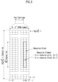
- a one-octet LBT failure MAC CE may be identified by a MAC subheader having a specific LCID (e.g., an LCID mapped to index/codepoint 43 or/and 49). As illustrated in (a) of FIG. 12 , the size of a one-octet LBT failure MAC CE is fixed and may consist of a single octet including eight C fields.
- a 4-octet LBT failure MAC CE may be identified by a MAC subheader having a specific LCID (e.g., an LCID mapped to index/codepoint 42 or/and 48). As illustrated in (b) of FIG. 12 , the size of a 4-octet LBT failure MAC CE is fixed and may consist of 4 octets containing 32 C fields.
- the highest 'ServCellIndex' of the serving cell of the MAC entity where the LBT failure was detected is less than 8
- the single octet format is used, otherwise the four octet format may be used.
- Ci may be set to 1. Otherwise, Ci may be set to 0.
- Embodiment 2 relates to a separate LBT failure detection and recovery procedures for SL LBT failure and UL LBT failure, and possibly the interaction between SL LBT failure and UL LBT failure.
- the UE may separately count the existing LBT_COUNTER based on LBT failures for UL transmissions in the UL BWP and the new LBT_COUNTER_SL based on LBT failures for SL transmissions in the SL BWP for each serving cell.
- the existing LBT failure MAC CE and the new LBT failure MAC CE may be generated separately for LBT failure of UL and LBT failure of SL, respectively.
- SR for UL LBT failure and SR for SL LBT failure may be triggered separately.
- SR configuration and resources may be separately configured and allocated for UL LBT failure and SL LBT failure reporting.
- Parameters of 'lbt-FailureRecoveryConfig' may be individually configured via RRC for UL LBT failure and SL LBT failure respectively.
- the following UE parameters may be used for a consistent LBT failure detection procedure for SL LBT failures.
- the MAC entity of the terminal may perform the following actions:
- One octet LBT failure MAC CE and SL LBT failure MAC CE may be identified by a MAC subheader with a specific LCID. As illustrated in (a) of FIG. 12 , the size of one octet LBT failure MAC CE is fixed and may be composed of a single octet including eight C fields.
- 4-octet LBT failure MAC CE and SL LBT failure MAC CE may be identified by a MAC subheader with a specific LCID. As shown in (b) of Fig. 12 , the size of the 4-octet LBT failure MAC CE is fixed and can be composed of 4 octets including 32 C fields.
- the UCID value for UL-SCH may be defined as shown in Table 10 below. [Table 10] Codepoint/Index LCID value 42 SL LBT failure (4 Octet) 43 SL LBT failure (1 Octet) 48 UL LBT failure (4 Octet) 49 UL LBT failure (1 Octet)
- the highest 'ServCellIndex' of the serving cell of the MAC entity where the LBT failure is detected is less than 8, the single octet format is used, otherwise the four octet format may be used.
- Ci may be set to 1. Otherwise, Ci may be set to 0.
- embodiment 1 or embodiment 2 may depend on the SL mode or the serving cell where SL transmission is performed. For example, embodiment 1 may be used in SL mode 1, and embodiment 2 may be used in SL mode 2. Embodiment 1 may be used in a serving cell where both UL and SL transmissions are allowed, and embodiment 2 may be used in a serving cell. In this case, only SL transmission may be allowed, and UL transmission may not be allowed.
- Embodiment 3 relates to the operation of a Tx terminal performed subsequent to Embodiment 1 and/or Embodiment 2.
- the MAC entity may perform a TX resource (re)selection check from the selected resource pool for the corresponding sidelink process.
- the condition(s) are as follows:
- Option 1 If the transmission corresponds to the last transmission of a MAC PDU, the UE may decrement the SL_RESOURCE_RESELECTION_COUNTER by 1 (if available) even if the last transmission was not transmitted due to an SL LBT failure.
- Option 2 If a transmission of a MAC PDU is not performed due to an LBT failure when the terminal determines the last transmission of a MAC PDU for the SL_RESOURCE_RESELECTION_COUNTER, the failed transmission may not be included in the number of transmissions of the MAC PDU.
- 'sl-ProbResourceKeep' may be scaled up or down based on consistent LBT failures for the SL.
- a certain number of LBT failures in a selected sidelink grant or SL BWP may increase or decrease the value of 'sl-ProbResourceKeep'. For example, by multiplying 'sl-ProbResourceKeep' by N/10, N may be determined by the number of LBT failures or triggered consistent LBT failures.
- the UE may perform retransmission of the MAC PDU using the next transmission opportunity of the sidelink grant selected in the next COT.
- the UE may reserve additional resource(s) within the COT and add the additional reserved resource(s) to the selected sidelink grant (i.e., the UE may not clear the selected sidelink grant).
- the UE may clear the selected sidelink grant associated with the sidelink process and trigger TX resource (re)selection.
- 'lbt-FailureInstanceMaxCount' for consistent LBT failure detection may be set to different values for different alternatives.
Landscapes
- Engineering & Computer Science (AREA)
- Computer Networks & Wireless Communication (AREA)
- Signal Processing (AREA)
- Mobile Radio Communication Systems (AREA)
Applications Claiming Priority (2)
| Application Number | Priority Date | Filing Date | Title |
|---|---|---|---|
| US202263335189P | 2022-04-26 | 2022-04-26 | |
| PCT/KR2023/005698 WO2023211153A1 (fr) | 2022-04-26 | 2023-04-26 | Procédé et appareil permettant de réaliser une communication de liaison latérale dans un système de communication sans fil |
Publications (1)
| Publication Number | Publication Date |
|---|---|
| EP4518529A1 true EP4518529A1 (fr) | 2025-03-05 |
Family
ID=88519198
Family Applications (1)
| Application Number | Title | Priority Date | Filing Date |
|---|---|---|---|
| EP23796796.3A Pending EP4518529A1 (fr) | 2022-04-26 | 2023-04-26 | Procédé et appareil permettant de réaliser une communication de liaison latérale dans un système de communication sans fil |
Country Status (6)
| Country | Link |
|---|---|
| US (1) | US20250392932A1 (fr) |
| EP (1) | EP4518529A1 (fr) |
| JP (1) | JP2025514210A (fr) |
| KR (1) | KR20250003917A (fr) |
| CN (1) | CN119014107A (fr) |
| WO (1) | WO2023211153A1 (fr) |
Families Citing this family (1)
| Publication number | Priority date | Publication date | Assignee | Title |
|---|---|---|---|---|
| US20240314834A1 (en) * | 2023-03-16 | 2024-09-19 | Samsung Electronics Co., Ltd. | Channel access procedures for multiple sl transmissions |
Family Cites Families (3)
| Publication number | Priority date | Publication date | Assignee | Title |
|---|---|---|---|---|
| WO2021002713A1 (fr) * | 2019-07-02 | 2021-01-07 | Samsung Electronics Co., Ltd. | Procédé de sélection de ressources et appareil de transmission latérale |
| EP4005278B1 (fr) * | 2019-07-25 | 2024-06-05 | FG Innovation Company Limited | Procédé et appareil de gestion d'échec de protocole lbt |
| US11576211B2 (en) * | 2019-12-19 | 2023-02-07 | Qualcomm Incorporated | Autonomous sidelink over unlicensed band |
-
2023
- 2023-04-26 CN CN202380035773.0A patent/CN119014107A/zh active Pending
- 2023-04-26 WO PCT/KR2023/005698 patent/WO2023211153A1/fr not_active Ceased
- 2023-04-26 KR KR1020247038662A patent/KR20250003917A/ko active Pending
- 2023-04-26 EP EP23796796.3A patent/EP4518529A1/fr active Pending
- 2023-04-26 US US18/856,488 patent/US20250392932A1/en active Pending
- 2023-04-26 JP JP2024563373A patent/JP2025514210A/ja active Pending
Also Published As
| Publication number | Publication date |
|---|---|
| JP2025514210A (ja) | 2025-05-02 |
| US20250392932A1 (en) | 2025-12-25 |
| KR20250003917A (ko) | 2025-01-07 |
| CN119014107A (zh) | 2024-11-22 |
| WO2023211153A1 (fr) | 2023-11-02 |
Similar Documents
| Publication | Publication Date | Title |
|---|---|---|
| US11824666B2 (en) | Method and apparatus for transmitting and receiving control information in wireless communication system | |
| EP4518538A1 (fr) | Procédé et dispositif de mise en oeuvre de communication de liaison latérale dans un système de communication sans fil | |
| EP4161165A1 (fr) | Procédé et appareil pour une régulation de puissance d'un pucch lors d'une rétroaction harq-ack | |
| EP4518529A1 (fr) | Procédé et appareil permettant de réaliser une communication de liaison latérale dans un système de communication sans fil | |
| EP4518555A1 (fr) | Procédé et dispositif de réalisation d'une communication de liaison latérale dans un système de communication sans fil | |
| EP4518473A1 (fr) | Procédé et dispositif permettant d'effectuer une communication de liaison latérale dans un système de communication sans fil | |
| EP4518530A1 (fr) | Procédé et appareil permettant de réaliser une communication de liaison latérale dans un système de communication sans fil | |
| EP4518532A1 (fr) | Procédé et dispositif permettant de réaliser une communication de liaison latérale dans un système de communication sans fil | |
| EP4518536A1 (fr) | Procédé et dispositif permettant de réaliser une communication de liaison latérale dans un système de communication sans fil | |
| EP4271073B1 (fr) | Procédé et appareil pour effectuer une communication de liaison latérale dans un système de communication sans fil | |
| US20250294584A1 (en) | Method and device for sidelink transmission or reception in wireless communication system | |
| EP4478637A1 (fr) | Procédé et dispositif de transmission et de réception en liaison montante dans un système de communication sans fil | |
| EP4280471A1 (fr) | Procédé et dispositif d'application d'un paramètre spatial dans un système de communication sans fil | |
| EP4518531A1 (fr) | Procédé et dispositif pour la réalisation d'une communication de liaison latérale dans un système de communication sans fil | |
| EP4518533A1 (fr) | Procédé et appareil permettant de réaliser une communication de liaison latérale dans un système de communication sans fil | |
| EP4518556A1 (fr) | Procédé et dispositif permettant de réaliser une communication de liaison latérale dans un système de communication sans fil | |
| EP4518534A1 (fr) | Procédé et dispositif permettant de réaliser une communication de liaison latérale dans un système de communication sans fil | |
| EP4518537A1 (fr) | Procédé et dispositif d'exécution d'une communication en liaison latérale dans un système de communication sans fil | |
| EP4694355A1 (fr) | Procédé et dispositif pour effectuer une procédure de relais d'ue à ue dans un système de communication sans fil | |
| EP4280770A1 (fr) | Procédé et dispositif d'émission et de réception en liaison montante dans un système de communication sans fil |
Legal Events
| Date | Code | Title | Description |
|---|---|---|---|
| STAA | Information on the status of an ep patent application or granted ep patent |
Free format text: STATUS: THE INTERNATIONAL PUBLICATION HAS BEEN MADE |
|
| PUAI | Public reference made under article 153(3) epc to a published international application that has entered the european phase |
Free format text: ORIGINAL CODE: 0009012 |
|
| STAA | Information on the status of an ep patent application or granted ep patent |
Free format text: STATUS: REQUEST FOR EXAMINATION WAS MADE |
|
| 17P | Request for examination filed |
Effective date: 20241121 |
|
| AK | Designated contracting states |
Kind code of ref document: A1 Designated state(s): AL AT BE BG CH CY CZ DE DK EE ES FI FR GB GR HR HU IE IS IT LI LT LU LV MC ME MK MT NL NO PL PT RO RS SE SI SK SM TR |
|
| DAV | Request for validation of the european patent (deleted) | ||
| DAX | Request for extension of the european patent (deleted) |