EP4518532A1 - Procédé et dispositif permettant de réaliser une communication de liaison latérale dans un système de communication sans fil - Google Patents
Procédé et dispositif permettant de réaliser une communication de liaison latérale dans un système de communication sans fil Download PDFInfo
- Publication number
- EP4518532A1 EP4518532A1 EP23796801.1A EP23796801A EP4518532A1 EP 4518532 A1 EP4518532 A1 EP 4518532A1 EP 23796801 A EP23796801 A EP 23796801A EP 4518532 A1 EP4518532 A1 EP 4518532A1
- Authority
- EP
- European Patent Office
- Prior art keywords
- lbt
- mac
- consistent
- lbt failure
- base station
- Prior art date
- Legal status (The legal status is an assumption and is not a legal conclusion. Google has not performed a legal analysis and makes no representation as to the accuracy of the status listed.)
- Pending
Links
Images



Classifications
-
- H—ELECTRICITY
- H04—ELECTRIC COMMUNICATION TECHNIQUE
- H04W—WIRELESS COMMUNICATION NETWORKS
- H04W72/00—Local resource management
- H04W72/20—Control channels or signalling for resource management
- H04W72/25—Control channels or signalling for resource management between terminals via a wireless link, e.g. sidelink
-
- H—ELECTRICITY
- H04—ELECTRIC COMMUNICATION TECHNIQUE
- H04W—WIRELESS COMMUNICATION NETWORKS
- H04W72/00—Local resource management
- H04W72/20—Control channels or signalling for resource management
- H04W72/23—Control channels or signalling for resource management in the downlink direction of a wireless link, i.e. towards a terminal
-
- H—ELECTRICITY
- H04—ELECTRIC COMMUNICATION TECHNIQUE
- H04L—TRANSMISSION OF DIGITAL INFORMATION, e.g. TELEGRAPHIC COMMUNICATION
- H04L1/00—Arrangements for detecting or preventing errors in the information received
- H04L1/12—Arrangements for detecting or preventing errors in the information received by using return channel
- H04L1/16—Arrangements for detecting or preventing errors in the information received by using return channel in which the return channel carries supervisory signals, e.g. repetition request signals
- H04L1/18—Automatic repetition systems, e.g. Van Duuren systems
- H04L1/1812—Hybrid protocols; Hybrid automatic repeat request [HARQ]
-
- H—ELECTRICITY
- H04—ELECTRIC COMMUNICATION TECHNIQUE
- H04L—TRANSMISSION OF DIGITAL INFORMATION, e.g. TELEGRAPHIC COMMUNICATION
- H04L1/00—Arrangements for detecting or preventing errors in the information received
- H04L1/12—Arrangements for detecting or preventing errors in the information received by using return channel
- H04L1/16—Arrangements for detecting or preventing errors in the information received by using return channel in which the return channel carries supervisory signals, e.g. repetition request signals
- H04L1/18—Automatic repetition systems, e.g. Van Duuren systems
-
- H—ELECTRICITY
- H04—ELECTRIC COMMUNICATION TECHNIQUE
- H04L—TRANSMISSION OF DIGITAL INFORMATION, e.g. TELEGRAPHIC COMMUNICATION
- H04L1/00—Arrangements for detecting or preventing errors in the information received
- H04L1/12—Arrangements for detecting or preventing errors in the information received by using return channel
- H04L1/16—Arrangements for detecting or preventing errors in the information received by using return channel in which the return channel carries supervisory signals, e.g. repetition request signals
- H04L1/18—Automatic repetition systems, e.g. Van Duuren systems
- H04L1/1822—Automatic repetition systems, e.g. Van Duuren systems involving configuration of automatic repeat request [ARQ] with parallel processes
-
- H—ELECTRICITY
- H04—ELECTRIC COMMUNICATION TECHNIQUE
- H04W—WIRELESS COMMUNICATION NETWORKS
- H04W24/00—Supervisory, monitoring or testing arrangements
- H04W24/08—Testing, supervising or monitoring using real traffic
-
- H—ELECTRICITY
- H04—ELECTRIC COMMUNICATION TECHNIQUE
- H04W—WIRELESS COMMUNICATION NETWORKS
- H04W72/00—Local resource management
- H04W72/04—Wireless resource allocation
- H04W72/044—Wireless resource allocation based on the type of the allocated resource
- H04W72/0453—Resources in frequency domain, e.g. a carrier in FDMA
-
- H—ELECTRICITY
- H04—ELECTRIC COMMUNICATION TECHNIQUE
- H04W—WIRELESS COMMUNICATION NETWORKS
- H04W72/00—Local resource management
- H04W72/04—Wireless resource allocation
- H04W72/044—Wireless resource allocation based on the type of the allocated resource
- H04W72/0457—Variable allocation of band or rate
-
- H—ELECTRICITY
- H04—ELECTRIC COMMUNICATION TECHNIQUE
- H04W—WIRELESS COMMUNICATION NETWORKS
- H04W72/00—Local resource management
- H04W72/20—Control channels or signalling for resource management
- H04W72/21—Control channels or signalling for resource management in the uplink direction of a wireless link, i.e. towards the network
-
- H—ELECTRICITY
- H04—ELECTRIC COMMUNICATION TECHNIQUE
- H04W—WIRELESS COMMUNICATION NETWORKS
- H04W74/00—Wireless channel access
- H04W74/08—Non-scheduled access, e.g. ALOHA
- H04W74/0808—Non-scheduled access, e.g. ALOHA using carrier sensing, e.g. carrier sense multiple access [CSMA]
-
- H—ELECTRICITY
- H04—ELECTRIC COMMUNICATION TECHNIQUE
- H04W—WIRELESS COMMUNICATION NETWORKS
- H04W76/00—Connection management
- H04W76/10—Connection setup
- H04W76/18—Management of setup rejection or failure
-
- H—ELECTRICITY
- H04—ELECTRIC COMMUNICATION TECHNIQUE
- H04W—WIRELESS COMMUNICATION NETWORKS
- H04W72/00—Local resource management
- H04W72/40—Resource management for direct mode communication, e.g. D2D or sidelink
-
- H—ELECTRICITY
- H04—ELECTRIC COMMUNICATION TECHNIQUE
- H04W—WIRELESS COMMUNICATION NETWORKS
- H04W92/00—Interfaces specially adapted for wireless communication networks
- H04W92/16—Interfaces between hierarchically similar devices
- H04W92/18—Interfaces between hierarchically similar devices between terminal devices
Definitions
- the present disclosure relates to a wireless communication system, and more particularly, to a method and device for performing sidelink communication in a wireless communication system.
- a mobile communication system has been developed to provide a voice service while guaranteeing mobility of users.
- a mobile communication system has extended even to a data service as well as a voice service, and currently, an explosive traffic increase has caused shortage of resources and users have demanded a faster service, so a more advanced mobile communication system has been required.
- the technical problem of the present disclosure is to provide a method and device for performing sidelink communication in a wireless communication system.
- the technical problem of the present disclosure is to provide a method and device for detecting SL LBT in units of SL resource pool or/and RB set.
- the technical problem of the present disclosure is to provide a method and device for reporting information related to consistent SL LBT failure when consistent SL LBT failure is triggered.
- a method performed by a first user equipment (UE) in a wireless communication system may include receiving configuration information related to at least one resource block (RB) set for sidelink (SL) transmission from a base station; and based on a consistent SL LBT (listen before talk) failure being detected for a specific RB set among the at least one RB set, transmitting a MAC (medium access control) CE (control element) related to the consistent SL LBT failure to the base station, and the MAC CE may include information indicating that the consistent SL LBT failure was detected for the specific RB set.
- a MAC medium access control
- a method performed by a base station in a wireless communication system may include transmitting configuration information related to at least one resource block (RB) set for sidelink (SL) transmission to a first user equipment (UE); and based on a consistent SL LBT (listen before talk) failure being detected for a specific RB set among the at least one RB set, receiving a MAC (medium access control) CE (control element) related to the consistent SL LBT failure from the first UE, and the MAC CE may include information indicating that the consistent SL LBT failure was detected for the specific RB set.
- RB resource block
- UE user equipment
- a method and device for performing sidelink communication in a wireless communication system may be provided.
- a method and device for detecting SL LBT by SL resource pool or/and RB set units may be provided.
- a method and device for reporting information related to consistent SL LBT failure when a consistent SL LBT failure is triggered may be provided.
- the base station by reporting a MAC CE indicating a resource pool/RB set where a SL LBT failure is detected/triggered to a base station, the base station can identify the resource where the SL LBT failure occurred in more detail.
- an element when referred to as being “connected”, “combined” or “linked” to another element, it may include an indirect connection relation that yet another element presents therebetween as well as a direct connection relation.
- a term, “include” or “have”, specifies the presence of a mentioned feature, step, operation, component and/or element, but it does not exclude the presence or addition of one or more other features, stages, operations, components, elements and/or their groups.
- a term such as “first”, “second”, etc. is used only to distinguish one element from other element and is not used to limit elements, and unless otherwise specified, it does not limit an order or importance, etc. between elements. Accordingly, within a scope of the present disclosure, a first element in an embodiment may be referred to as a second element in another embodiment and likewise, a second element in an embodiment may be referred to as a first element in another embodiment.
- a term used in the present disclosure is to describe a specific embodiment, and is not to limit a claim. As used in a described and attached claim of an embodiment, a singular form is intended to include a plural form, unless the context clearly indicates otherwise.
- a term used in the present disclosure, "and/or”, may refer to one of related enumerated items or it means that it refers to and includes any and all possible combinations of two or more of them.
- "/" between words in the present disclosure has the same meaning as “and/or”, unless otherwise described.
- the present disclosure describes a wireless communication network or a wireless communication system, and an operation performed in a wireless communication network may be performed in a process in which a device (e.g., a base station) controlling a corresponding wireless communication network controls a network and transmits or receives a signal, or may be performed in a process in which a terminal associated to a corresponding wireless network transmits or receives a signal with a network or between terminals.
- a device e.g., a base station
- transmitting or receiving a channel includes a meaning of transmitting or receiving information or a signal through a corresponding channel.
- transmitting a control channel means that control information or a control signal is transmitted through a control channel.
- transmitting a data channel means that data information or a data signal is transmitted through a data channel.
- a downlink means a communication from a base station to a terminal
- an uplink means a communication from a terminal to a base station.
- a transmitter may be part of a base station and a receiver may be part of a terminal.
- a transmitter may be part of a terminal and a receiver may be part of a base station.
- a base station may be expressed as a first communication device and a terminal may be expressed as a second communication device.
- a base station may be substituted with a term such as a fixed station, a Node B, an eNB(evolved-NodeB), a gNB(Next Generation NodeB), a BTS(base transceiver system), an Access Point (AP), a Network(5G network), an AI (Artificial Intelligence) system/module, an RSU(road side unit), a robot, a drone(UAV: Unmanned Aerial Vehicle), an AR(Augmented Reality) device, a VR(Virtual Reality) device, etc.
- a term such as a fixed station, a Node B, an eNB(evolved-NodeB), a gNB(Next Generation NodeB), a BTS(base transceiver system), an Access Point (AP), a Network(5G network), an AI (Artificial Intelligence) system/module, an RSU(road side unit), a robot, a drone(UAV: Unmanned Aerial Vehicle), an AR
- a terminal may be fixed or mobile, and may be substituted with a term such as a UE(User Equipment), an MS(Mobile Station), a UT(user terminal), an MSS(Mobile Subscriber Station), an SS(Subscriber Station), an AMS(Advanced Mobile Station), a WT(Wireless terminal), an MTC(Machine-Type Communication) device, an M2M(Machine-to-Machine) device, a D2D(Device-to-Device) device, a vehicle, an RSU(road side unit), a robot, an AI(Artificial Intelligence) module, a drone(UAV: Unmanned Aerial Vehicle), an AR(Augmented Reality) device, a VR(Virtual Reality) device, etc.
- a term such as a UE(User Equipment), an MS(Mobile Station), a UT(user terminal), an MSS(Mobile Subscriber Station), an SS(Subscriber Station), an AMS(Advanced Mobile Station
- CDMA may be implemented by a wireless technology such as UTRA(Universal Terrestrial Radio Access) or CDMA2000.
- TDMA may be implemented by a radio technology such as GSM(Global System for Mobile communications)/GPRS(General Packet Radio Service)/EDGE(Enhanced Data Rates for GSM Evolution).
- OFDMA may be implemented by a radio technology such as IEEE 802.11(Wi-Fi), IEEE 802.16(WiMAX), IEEE 802-20, E-UTRA(Evolved UTRA), etc.
- UTRA is a part of a UMTS (Universal Mobile Telecommunications System).
- 3GPP(3rd Generation Partnership Project) LTE(Long Term Evolution) is a part of an E-UMTS (Evolved UMTS) using E-UTRA and LTE-A(Advanced)/LTE-A pro is an advanced version of 3GPP LTE.
- 3GPP NR(New Radio or New Radio Access Technology) is an advanced version of 3GPP LTE/LTE-A/LTE-A pro.
- LTE means a technology after 3GPP TS(Technical Specification) 36.xxx Release 8.
- LTE-A an LTE technology in or after 3GPP TS 36.
- xxx Release 10 is referred to as LTE-A
- LTE-A pro an LTE technology in or after 3GPP TS 36.
- xxx Release 13 is referred to as LTE-A pro.
- 3GPP NR means a technology in or after TS 38.xxx Release 15.
- LTE/NR may be referred to as a 3GPP system.
- "xxx" means a detailed number for a standard document.
- LTE/NR may be commonly referred to as a 3GPP system.
- a term, an abbreviation, etc. used to describe the present disclosure matters described in a standard document disclosed before the present disclosure may be referred to.
- the following document may be referred to.
- TS 36.211 physical channels and modulation
- TS 36.212 multiplexing and channel coding
- TS 36.213 physical layer procedures
- TS 36.300 overall description
- TS 36.331 radio resource control
- TS 38.211 physical channels and modulation
- TS 38.212 multiplexing and channel coding
- TS 38.213 physical layer procedures for control
- TS 38.214 physical layer procedures for data
- TS 38.300 NR and NG-RAN(New Generation-Radio Access Network) overall description
- TS 38.331 radio resource control protocol specification
- NR is an expression which represents an example of a 5G RAT.
- a new RAT system including NR uses an OFDM transmission method or a transmission method similar to it.
- a new RAT system may follow OFDM parameters different from OFDM parameters of LTE.
- a new RAT system follows a numerology of the existing LTE/LTE-A as it is, but may support a wider system bandwidth (e.g., 100MHz).
- one cell may support a plurality of numerologies. In other words, terminals which operate in accordance with different numerologies may coexist in one cell.
- NR supports a plurality of numerologies (or subcarrier spacings (SCS)) for supporting a variety of 5G services. For example, when a SCS is 15kHz, a wide area in traditional cellular bands is supported, and when a SCS is 30kHz/60kHz, dense-urban, lower latency and a wider carrier bandwidth are supported, and when a SCS is 60kHz or higher, a bandwidth wider than 24.25GHz is supported to overcome a phase noise.
- An NR frequency band is defined as a frequency range in two types (FR1, FR2).
- FR1, FR2 may be configured as in the following Table 2.
- FR2 may mean a millimeter wave (mmW).
- mmW millimeter wave
- Table 3 represents the number of OFDM symbols per slot (N symb slot ), the number of slots per radio frame (N slot frame, ⁇ ) and the number of slots per subframe (N slot subframe, ⁇ ) in a normal CP and Table 4 represents the number of OFDM symbols per slot, the number of slots per radio frame and the number of slots per subframe in an extended CP.
- Table 3 ⁇ N symb slot N slot frame, ⁇ N slot subframe, ⁇ 0 14 10 1 1 14 20 2 2 14 40 4 3 14 80 8 4 14 160 16
- Table 4 ⁇ N symb slot N slot frame, ⁇ N slot subframe, ⁇ 2 12 40 4
- a mini-slot may include 2, 4 or 7 symbols or more or less symbols.
- a physical resource in a NR system an antenna port, a resource grid, a resource element, a resource block, a carrier part, etc. may be considered.
- the physical resources which may be considered in an NR system will be described in detail.
- an antenna port in relation to an antenna port, is defined so that a channel where a symbol in an antenna port is carried can be inferred from a channel where other symbol in the same antenna port is carried.
- a large-scale property of a channel where a symbol in one antenna port is carried may be inferred from a channel where a symbol in other antenna port is carried, it may be said that 2 antenna ports are in a QC/QCL(quasi co-located or quasi co-location) relationship.
- the large-scale property includes at least one of delay spread, doppler spread, frequency shift, average received power, received timing.
- FIG. 3 illustrates a resource grid in a wireless communication system to which the present disclosure may be applied.
- a resource grid is configured with N RB ⁇ N sc RB subcarriers in a frequency domain and one subframe is configured with 14 ⁇ 2 ⁇ OFDM symbols, but it is not limited thereto.
- a transmitted signal is described by OFDM symbols of 2 ⁇ N symb ( ⁇ ) and one or more resource grids configured with N RB ⁇ N sc RB subcarriers.
- N RB ⁇ N RB max, ⁇ represents a maximum transmission bandwidth, which may be different between an uplink and a downlink as well as between numerologies.
- one resource grid may be configured per ⁇ and antenna port p.
- Each element of a resource grid for ⁇ and an antenna port p is referred to as a resource element and is uniquely identified by an index pair (k,l').
- an index pair (k,l) is used.
- l 0, ...,N symb ⁇ -1.
- a resource element (k,l') for ⁇ and an antenna port p corresponds to a complex value, a k,l' (p, ⁇ ) .
- indexes p and ⁇ may be dropped, whereupon a complex value may be a k,l' (p) or a k,l' .
- Point A plays a role as a common reference point of a resource block grid and is obtained as follows.
- Physical resource blocks are numbered from 0 to N BWP,i size, ⁇ -1 in a bandwidth part (BWP) and i is a number of a BWP.
- a relationship between a physical resource block n PRB and a common resource block n CRB in BWP i is given by the following Equation 2.
- N BWP,i start, ⁇ is a common resource block that a BWP starts relatively to common resource block 0.
- FIG. 4 illustrates a physical resource block in a wireless communication system to which the present disclosure may be applied.
- FIG. 5 illustrates a slot structure in a wireless communication system to which the present disclosure may be applied.
- a slot includes a plurality of symbols in a time domain. For example, for a normal CP, one slot includes 7 symbols, but for an extended CP, one slot includes 6 symbols.
- a carrier includes a plurality of subcarriers in a frequency domain.
- An RB Resource Block
- a BWP(Bandwidth Part) is defined as a plurality of consecutive (physical) resource blocks in a frequency domain and may correspond to one numerology (e.g., an SCS, a CP length, etc.).
- a carrier may include a maximum N (e.g., 5) BWPs.
- a data communication may be performed through an activated BWP and only one BWP may be activated for one terminal.
- each element is referred to as a resource element (RE) and one complex symbol may be mapped.
- RE resource element
- a terminal operating in such a wideband CC may always operate turning on a radio frequency (FR) chip for the whole CC, terminal battery consumption may increase.
- FR radio frequency
- a different numerology e.g., a subcarrier spacing, etc.
- each terminal may have a different capability for the maximum bandwidth.
- a base station may indicate a terminal to operate only in a partial bandwidth, not in a full bandwidth of a wideband CC, and a corresponding partial bandwidth is defined as a bandwidth part (BWP) for convenience.
- a BWP may be configured with consecutive RBs on a frequency axis and may correspond to one numerology (e.g., a subcarrier spacing, a CP length, a slot/a mini-slot duration).
- a configuration on a DL/UL BWP may not be received when a terminal performs an initial access procedure or before a RRC connection is set up, so a DL/UL BWP which is assumed by a terminal under these situations is defined as an initial active DL/UL BWP.
- FIG. 6 illustrates physical channels used in a wireless communication system to which the present disclosure may be applied and a general signal transmission and reception method using them.
- a terminal receives information through a downlink from a base station and transmits information through an uplink to a base station.
- Information transmitted and received by a base station and a terminal includes data and a variety of control information and a variety of physical channels exist according to a type/a usage of information transmitted and received by them.
- a terminal When a terminal is turned on or newly enters a cell, it performs an initial cell search including synchronization with a base station or the like (S601).
- a terminal may synchronize with a base station by receiving a primary synchronization signal (PSS) and a secondary synchronization signal (SSS) from a base station and obtain information such as a cell identifier (ID), etc.
- PSS primary synchronization signal
- SSS secondary synchronization signal
- ID cell identifier
- a terminal may obtain broadcasting information in a cell by receiving a physical broadcast channel (PBCH) from a base station.
- PBCH physical broadcast channel
- a terminal may check out a downlink channel state by receiving a downlink reference signal (DL RS) at an initial cell search stage.
- DL RS downlink reference signal
- a terminal which completed an initial cell search may obtain more detailed system information by receiving a physical downlink control channel (PDCCH) and a physical downlink shared channel (PDSCH) according to information carried in the PDCCH (S602).
- PDCCH physical downlink control channel
- PDSCH physical downlink shared channel
- a terminal which performed the above-described procedure subsequently may perform PDCCH/PDSCH reception (S607) and PUSCH (Physical Uplink Shared Channel) /PUCCH (physical uplink control channel) transmission (S608) as a general uplink/downlink signal transmission procedure.
- a terminal receives downlink control information (DCI) through a PDCCH.
- DCI includes control information such as resource allocation information for a terminal and a format varies depending on its purpose of use.
- control information which is transmitted by a terminal to a base station through an uplink or is received by a terminal from a base station includes a downlink/uplink ACK/NACK(Acknowledgement/Non-Acknowledgement) signal, a CQI(Channel Quality Indicator), a PMI(Precoding Matrix Indicator), a RI(Rank Indicator), etc.
- a terminal may transmit control information of the above-described CQI/PMI/RI, etc. through a PUSCH and/or a PUCCH.
- Table 5 represents an example of a DCI format in an NR system.
- DCI Format Use 0_0 Scheduling of a PUSCH in one cell 0_1 Scheduling of one or multiple PUSCHs in one cell, or indication of cell group downlink feedback information to a UE 0_2 Scheduling of a PUSCH in one cell 1_0 Scheduling of a PDSCH in one DL cell 1_1 Scheduling of a PDSCH in one cell 1_2 Scheduling of a PDSCH in one cell
- DCI formats 0_0, 0_1 and 0_2 may include resource information (e.g., UL/SUL (Supplementary UL), frequency resource allocation, time resource allocation, frequency hopping, etc.), information related to a transport block(TB) (e.g., MCS(Modulation Coding and Scheme), a NDI(New Data Indicator), a RV(Redundancy Version), etc.), information related to a HARQ(Hybrid - Automatic Repeat and request) (e.g., a process number, a DAI(Downlink Assignment Index), PDSCH-HARQ feedback timing, etc.), information related to multiple antennas (e.g., DMRS sequence initialization information, an antenna port, a CSI request, etc.), power control information (e.g., PUSCH power control, etc.) related to scheduling of a PUSCH and control information included in each DCI format may be pre-defined.
- resource information e.g., UL/SUL (Sup
- DCI format 0_0 is used for scheduling of a PUSCH in one cell.
- Information included in DCI format 0_0 is CRC (cyclic redundancy check) scrambled by a C-RNTI(Cell Radio Network Temporary Identifier) or a CS-RNTI(Configured Scheduling RNTI) or a MCS-C-RNTI(Modulation Coding Scheme Cell RNTI) and transmitted.
- CRC cyclic redundancy check
- DCI format 0_2 is used for scheduling of a PUSCH in one cell.
- Information included in DCI format 0_2 is CRC scrambled by a C-RNTI or a CS-RNTI or a SP-CSI-RNTI or a MCS-C-RNTI and transmitted.
- DCI formats 1_0, 1_1 and 1_2 may include resource information (e.g., frequency resource allocation, time resource allocation, VRB(virtual resource block)-PRB(physical resource block) mapping, etc.), information related to a transport block(TB) (e.g., MCS, NDI, RV, etc.), information related to a HARQ (e.g., a process number, DAI, PDSCH-HARQ feedback timing, etc.), information related to multiple antennas (e.g., an antenna port, a TCI(transmission configuration indicator), a SRS(sounding reference signal) request, etc.), information related to a PUCCH (e.g., PUCCH power control, a PUCCH resource indicator, etc.) related to scheduling of a PDSCH and control information included in each DCI format may be pre-defined.
- resource information e.g., frequency resource allocation, time resource allocation, VRB(virtual resource block)-PRB(physical resource block) mapping, etc.
- DCI format 1_0 is used for scheduling of a PDSCH in one DL cell.
- Information included in DCI format 1_0 is CRC scrambled by a C-RNTI or a CS-RNTI or a MCS-C-RNTI and transmitted.
- DCI format 1_2 is used for scheduling of a PDSCH in one cell.
- Information included in DCI format 1_2 is CRC scrambled by a C-RNTI or a CS-RNTI or a MCS-C-RNTI and transmitted.
- V2X vehicle-to-everything
- SL sidelink
- FIG. 7 illustrates a procedure for performing V2X or SL communication according to a transmission mode in a wireless communication system to which the present disclosure may be applied.
- the transmission mode may be referred to as a mode or a resource allocation mode.
- the transmission mode in LTE may be referred to as an LTE transmission mode
- the transmission mode in NR may be referred to as an NR resource allocation mode.
- FIG. 7(a) illustrates the operation of a UE related to LTE transmission mode 1 or LTE transmission mode 3.
- FIG. 7(a) illustrates the operation of a UE related to NR resource allocation mode 1.
- LTE transmission mode 1 may be applied to general SL communication
- LTE transmission mode 3 may be applied to V2X communication.
- Fig. 7(b) illustrates the operation of a UE associated with LTE transmission mode 2 or LTE transmission mode 4.
- Fig. 7(b) illustrates the operation of a UE associated with NR resource allocation mode 2.
- the base station may schedule SL resources to be used by the UE for SL transmission (S8000). For example, the base station may transmit information related to SL resources and/or information related to UL resources to the first UE.
- the UL resources may include PUCCH resources and/or PUSCH resources.
- the UL resources may be resources for reporting SL HARQ feedback to the base station.
- the first UE may receive information related to a dynamic grant (DG) resource and/or information related to a configured grant (CG) resource from the base station.
- the CG resource may include a CG type 1 resource or a CG type 2 resource.
- the DG resource may be a resource that the base station configures/allocates to the first UE via DCI.
- the CG resource may be a (periodic) resource that the base station configures/allocates to the first UE via DCI and/or an RRC message.
- the base station may transmit an RRC message including information related to the CG resource to the first UE.
- the base station may transmit an RRC message including information related to the CG resource to the first UE, and the base station may transmit DCI related to activation or release of the CG resource to the first UE.
- the first UE may transmit PSCCH (e.g., Sidelink Control Information (SCI) or 1st-stage SCI) to the second UE based on the resource scheduling (S8010).
- PSCCH e.g., Sidelink Control Information (SCI) or 1st-stage SCI
- the first UE may transmit a PSSCH (e.g., a 2nd-stage SCI, a MAC protocol data unit (PDU), data, etc.) related to the PSCCH to the second UE (S8020).
- a PSSCH e.g., a 2nd-stage SCI, a MAC protocol data unit (PDU), data, etc.
- the first UE may receive a PSFCH related to the PSCCH/PSSCH from the second UE (S8030).
- HARQ feedback information e.g., NACK information or ACK information
- NACK information or ACK information can be received from the second UE via the PSFCH.
- the first UE may transmit/report HARQ feedback information to the base station via PUCCH or PUSCH (S8040).
- the HARQ feedback information reported to the base station may be information generated by the first UE based on HARQ feedback information received from the second UE.
- the HARQ feedback information reported to the base station may be information generated by the first UE based on a rule set in advance.
- the DCI may be DCI for scheduling of SL.
- the format of the DCI may be DCI format 3_0 or DCI format 3_1.
- the first UE may receive a PSFCH related to PSCCH/PSSCH from the second UE (S8030).
- a first UE may transmit an SCI to a second UE on a PSCCH.
- the first UE may transmit two consecutive SCIs (e.g., 2-stage SCIs) to the second UE on the PSCCH and/or the PSSCH.
- the second UE may decode the two consecutive SCIs (e.g., 2-stage SCIs) to receive the PSSCH from the first UE.
- the first UE may receive the PSFCH based on the description to be described below.
- the first UE and the second UE may determine the PSFCH resource based on the description to be described below, and the second UE may transmit the HARQ feedback to the first UE using the PSFCH resource.
- the UE may be provided with a number of slots within the resource pool during a period of PSFCH transmission occasion resources by sl-PSFCH-Period. If the number of slots is 0, the PSFCH transmission of the UE within the resource pool is disabled.
- the UE may be indicated by higher layers not to transmit a PSFCH containing HARQ-ACK information in response to receiving a PSSCH.
- the UE When a UE receives a PSSCH from a resource pool and the HARQ feedback enabled/disabled indicator field of the associated SCI format 2-A/2-B/2-C has value 1, the UE provides HARQ-ACK information in a PSFCH transmission from the resource pool.
- the UE transmits the PSFCH in the first slot that includes PSFCH resources and that corresponds to at least a number of slots provided by sl-MinTimeGapPSFCH of the resource pool after the last slot of the PSSCH reception.
- the UE may be provided with a set of M PRB,set PSFCH PRBs in the resource pool for PSFCH transmission including HARQ-ACK information in the physical resource block (PRB) of the resource pool by sl-PSFCH-RB-Set.
- the UE may be provided with a set of M PRB,set PSFCH PRBs in the resource pool by sl-RB-SetPSFCH for PSFCH transmission including conflict information in the PRB of the resource pool.
- the UE expects that different PRBs are (pre-)set for conflict information and HARQ-ACK information.
- the UE For the number of N SUBCH sub-channels for the resource pool provided by sl-NumSubchannel and the number of PSSCH slots associated with PSFCH slots less than or equal to N PSSCH PSFCH , the UE allocates [(i+j N PSSCH PSFCH ) M subch,slot' PSFCH (i+1+j N PSSCH PSFCH ) M subch,slot PSFCH -1] PRBs from M PRB,set PSFCH PRBs among the PSFCH slots and PSSCH slots associated with sub-channel j to slot i.
- M subch,slot PSECH M PPB,set PSFCH /(N subch N PSSCH PSFCH ), 0 ⁇ i ⁇ N PSSCH PSFCH , 0 ⁇ j ⁇ N subch , and the allocation starts in ascending order of i and continues in ascending order of j.
- the UE expects M PRB,set PSFCH to be a multiple of N subch ⁇ N PSSCH PSFCH .
- the UE determines the index of the PSFCH resource for transmitting the PSFCH including HARQ-ACK information or conflict information in response to the PSSCH reception, which corresponds to the reserved resource, as (P ID +M ID ) mod RPRB,CS PSECH .
- P ID is a physical layer source identifier provided by SCI format 2-A/2-B/2-C that schedules PSSCH reception or SCI format 2-A/2-B/2-C that reserves resources for conflict information to be provided from other UEs.
- M ID is an identifier of the UE that receives the PSSCH indicated by the upper layer, otherwise M ID is 0.
- M ID is 0.
- the UE determines the value m 0 from the cyclic shift pair index corresponding to the PSFCH resource index and from N CS PSFCH using Table 6 below to calculate the value ⁇ of the cyclic shift.
- Table 6 illustrates a set of cyclic shift pairs.
- N CS PSFCH m 0 Cyclic shift pair index 0 Cyclic shift pair index 1 Cyclic shift pair index 2 Cyclic shift pair index 3 Cyclic shift pair index 4 Cyclic shift pair index 5 1 0 - - - - - 2 0 3 - - - - 3 0 2 4 - - - 6 0 1 2 3 4 5
- the UE determines a m cs value as shown in Table 7 below if the UE detects an SCI format 2-A or SCI format 2-C having a cast type indicator field value of "01" or "10" to calculate the value ⁇ of the cyclic shift, and determines an m cs value as shown in Table 8 below if the UE detects an SCI format 2-B or 2-A having a cast type indicator field value of "11".
- the UE determines an m cs value as shown in Table 9 below to calculate the value ⁇ of the cyclic shift.
- the UE applies one cyclic shift from a cyclic shift pair to a sequence used for PSFCH transmission.
- Table 7 illustrates the mapping of cyclic shifts of a sequence for PSFCH transmission from a cyclic shift pair and HARQ-ACK information bit values when the HARQ-ACK information includes ACK or NACK.
- Table 9 illustrates the mapping of the cyclic shift of a sequence for PSFCH transmission and the value of the conflict information bit from a cyclic shift pair. [Table 9] Conflict information Conflict information for the next time-reserved resource within SCI Sequence cyclic shift 0
- FIG. 8 illustrates a cast type for V2X or SL communication in a wireless communication system to which the present disclosure may be applied.
- the embodiment of FIG. 8 may be combined with various embodiments of the present disclosure.
- FIG. 8(a) represents a broadcast type SL communication
- FIG. 8(b) represents a unicast type SL communication
- FIG. 8(c) represents a group-cast type SL communication.
- a UE can perform one-to-one communication with another UE.
- a UE may perform SL communication with one or more UEs within the group to which it belongs.
- SL group-cast communication may be referred to as SL multicast communication, SL one-to-many communication, etc.
- SL HARQ feedback may be enabled for group-cast.
- two HARQ feedback options may be supported for group-cast.
- all UEs performing group-cast communication may share PSFCH resources.
- UEs belonging to the same group may transmit HARQ feedback using the same PSFCH resources.
- each UE performing group-cast communication may use different PSFCH resources for HARQ feedback transmission.
- UEs belonging to the same group may transmit HARQ feedback using different PSFCH resources.
- Sidelink grants may be semi-persistently configured by RRC or received dynamically on the PDCCH, which is autonomously selected by the MAC entity.
- the MAC entity may have a sidelink grant on the active SL BWP to determine the set of PSCCH periods in which SCI transmissions occur and the set of PSSCH periods in which SL-SCH transmissions associated with SCI occur.
- the MAC entity may perform actions based on each PDCCH occasion and each grant received for that PDCCH occasion.
- NR Unlicensed Spectrum refers to a mode that provides the technology necessary for cellular operators to integrate unlicensed spectrum into their wireless communication systems.
- NR-U may enable both uplink and downlink operations in unlicensed spectrum.
- channel access for uplink and downlink relies on LBT functionality.
- the UE and/or base station may first sense the communication channel to determine if there is no communication before transmission. If the communication channel is a wideband unlicensed carrier, the channel sensing procedure of NR-U may rely on sensing energy levels in multiple subbands of the communication channel.
- the base station may configure LBT parameters (e.g., type/duration, clear channel assessment parameters, etc.) for the UE.
- a UE may determine the time and location of transmission and reception based on the indications of the COT (Channel Occupancy Time) structure.
- the COT consists of multiple slots, and each slot may consist of downlink resources, uplink resources, or flexible resources.
- both contiguous and interlaced uplink resource allocations may be supported while complying with the regulations.
- interlace uplink resource allocation the basic unit of resource allocation for an NR unlicensed channel may be an interlace.
- a single interlace may consist of ten equally spaced resource blocks within a 20 MHz frequency bandwidth for a 15 kHz subcarrier spacing.
- the physical layer may perform the LBT procedure.
- the LBT procedure means a procedure in which transmission is not performed when the channel is determined to be occupied. If the channel is identified as occupied according to the LBT procedure, transmission may not be performed by the physical layer. If the physical layer performs the LBT procedure before transmission and transmission is not performed, the physical layer may transmit an LBT failure indication to the MAC entity.
- the operations specified in the present disclosure may be performed regardless of whether an LBT failure indication is received from the physical layer when an LBT procedure is performed for transmission. If the physical layer does not perform LBT, an LBT failure indication may not be received from the physical layer.
- SR(Scheduling Request) may be triggered by LBT(Listen Before Talk) failure in UL transmission.
- the MAC entity may:
- the UE may perform LBT for SL transmission.
- LBT failure can occur not only in UL transmission but also in SL transmission. Therefore, when SL mode 1 is configured, the gNB may need to know whether LBT failure occurs for SL transmission.
- LBT failure reporting for SL transmission is not supported in basic wireless communication systems.
- the sidelink Tx (transmission) UE is referred to as the first UE
- the sidelink Rx (reception) UE is referred to as the second UE.
- the sidelink operation between the first UE and the second UE may operate in an unlicensed band/spectrum or a shared spectrum.
- FIG. 9 is a diagram for explaining a process in which a first UE performs communication according to one embodiment of the present disclosure.
- a first user equipment may receive configuration information related to at least one resource block (RB) set for sidelink (SL) transmission from a base station (S910).
- RB resource block
- S910 base station
- the configuration information associated with at least one RB set may include the number of RBs in at least one resource pool (configured by the base station), the lowest RB index of the lowest indexed subchannel within the resource pool, the number of RBs per RB set, etc.
- the first UE may receive from the base station configuration information related to an SL resource allocation mode, configuration information related to one or more SL resource pools, configuration information related to an SL RLC bearer, etc.
- the first UE may transmit a MAC CE related to the consistent SL LBT failure to the base station (S920).
- the first UE may transmit a MAC CE related to the consistent SL LBT failure to the base station.
- the first UE may detect/trigger an LBT failure for a specific RB set or a specific resource pool among at least one resource pool/RB set. Accordingly, the first UE may report a (SL LBT failure) MAC CE to the base station.
- the (SL LBT failure) MAC CE may include information indicating that a consistent SL LBT failure has been detected for the specific RB set/the specific resource pool.
- the (SL LBT Failure) MAC CE may include information indicating at least one of the cell or SL BWP in which a consistent SL LBT failure was detected.
- the first UE may transmit to the base station information for separate SL LBT failure reporting for the RB set, SL BWP, resource pool, or/and cell where (consistent) SL LBT failure occurred.
- Each of the LBT failure MAC CE in uplink and the new SL LBT failure MAC CE may be distinguished by different LCID values in the sub-header of the MAC PDU containing the corresponding MAC CE.
- the LCID corresponding to the sub-header of the MAC PDU including the MAC CE associated with the consistent SL LBT failure may be different from the LCID value corresponding to the sub-header of the MAC PDU including the MAC CE associated with the LBT failure in the uplink.
- SL LBT failures reported to the base station may be associated with SR resources. For example, if SL LBT failures are detected N or more times, the first UE may report this to the base station.
- the first UE may trigger an LBT failure MAC CE reporting UL LBT failure.
- the LBT failure MAC CE may report LBT failure for the cell where UL or SL LBT failure occurred (regardless of SL and UL).
- the first UE may transmit a physical uplink control channel (PUCCH) including SL HARQ-ACK information indicating a negative acknowledgement (NACK) and information indicating that the NACK is generated/caused by consistent SL LBT to the base station.
- PUCCH physical uplink control channel
- NACK negative acknowledgement
- the first UE m ay transmit to the base station a PUCCH including the NACK and information indicating that the NACK is generated/caused by consistent SL LBT.
- the NACK may be for a specific TB. That is, the first UE may report SL HARQ-ACK to the base station through the PUCCH only for a specific TB.
- the first UE may drop the SL transmission and transmit the PUCCH to the base station. Then, based on the SR (scheduling request) for MAC CE being triggered, the first UE may transmit the PUCCH allocated for the SR to the base station.
- the SR scheduling request
- the UE may receive an RRC (radio resource control) reconfiguration message from the base station to configure a new RB set/resource pool. Accordingly, the first UE may change the RB set/resource pool for SL communication from a specific RB set/specific resource pool to a new RB set/new resource pool.
- RRC radio resource control
- the first UE may change the RB set/resource pool for SL communication from a specific RB set/specific resource pool to the new RB set/specific resource pool.
- a DCI e.g., DCI format 3_x (where x is an integer greater than or equal to 0)
- MAC CE MAC CE
- the first UE may autonomously change the RB set/resource pool for SL communication from a specific RB set/specific resource pool to a new RB set/new resource pool.
- the first UE may change the RB set for SL communication from a specific RB set to a default RB set configured by the base station or to the SL RB set of the initial SL BWP associated with the initial UL BWP.
- the method performed by the first UE described in the example of FIG. 9 may be performed by the first device (100) of FIG. 13 .
- one or more processors (102) of the first device (100) of FIG. 13 may be configured to receive configuration information related to at least one RB set for SL transmission from a base station through one or more transceivers (106).
- the one or more processors (102) may be configured to transmit a MAC CE related to the consistent SL LBT failure to the base station through one or more transceivers (106) based on detecting a consistent SL LBT failure for a specific RB set among the at least one RB set.
- the base station may receive a MAC CE related to the consistent SL LBT failure from the first UE (S1020).
- the base station may receive a MAC CE related to the consistent SL LBT failure from the first terminal.
- the base station may identify that the SL LBT failure is detected/triggered for a specific RB set/specific resource pool through MAC CE related to consistent SL LBT failure.
- the base station may transmit an RRC reconfiguration message/DCI/DL MAC CE to the first UE so that the first UE may perform SL communication by changing from the specific RB set/specific resource pool to a new RB set/new resource pool.
- the method performed by the base station described in the example of FIG. 10 can be performed by the second device (200) of FIG. 13 .
- one or more memories (204) of the second device (200) may store instructions for performing the method described in the example of FIG. 10 when executed by one or more processors (202).
- FIG. 11 is for convenience of explanation and does not limit the scope of the present disclosure. Some of the step(s) illustrated in FIG. 11 may be omitted depending on the situation and/or setting.
- the Tx terminal/Rx terminal/base station in FIG. 11 is only an example and may be implemented with the device illustrated in FIG. 13 below.
- the base station may transmit configuration information to the transmitting UE via an RRC message (S1010).
- the configuration information may include information related to PUCCH resources for (SL) LBT failure, information related to SL resource allocation mode, and/or information related to SL resource pool.
- a transmitting UE may reserve sidelink resources (S1020). The transmitting UE may perform sidelink transmission using the reserved resources.
- the transmitting UE may monitor the PDCCH (S1030). If a DCI with CRC scrambled by SL-RNTI or SLCS-RNTI is received from the base station through the PDCCH, the transmitting UE may allocate sidelink resources according to the DCI. The transmitting UE may perform SL transmission using one of the resources received in the SL BWP of the cell. The transmitting UE may perform UL transmission on the UL BWP of the same cell. The SL BWP and the UL BWP may overlap in frequency in the same cell, but may not overlap in time.
- the transmitting UE may selectively perform the operation according to step S1020 and the operation according to step S1030 depending on the sidelink resource allocation mode.
- the physical layer (i.e., L1) of a transmitting UE may perform a channel access procedure.
- the transmitting UE may access a channel on which SL or UL transmission(s) are performed according to either a Type 1 or Type 2 UL channel access procedure.
- the physical layer may notify the MAC layer of a channel access failure (i.e., LBT failure).
- SL mode 1 For SL (re)transmission of TB on SL resource according to SL mode 1 (or SL mode 2), if the physical layer of the transmitting UE notifies the MAC layer of LBT failure for SL transmission of TB, and if the PUCCH resource is configured with SL mode 1, the transmitting UE may transmit ' NACK ' to the base station through PUCCH for reporting SL HARQ-ACK information.
- the UE may transmit ' NACK ' to the base station via PUCCH using the PUCCH resource allocated to report SL HARQ-ACK information even if it does not receive SL HARQ feedback.
- PUCCH resources may be associated with SL resources used for SL transmission of TB (e.g., in terms of HARQ process ID of TB).
- UCI of PUCCH may indicate whether the reported NACK is caused by LBT failure (i.e., PSSCH is not transmitted due to LBT failure).
- the two bits on PUCCH format 0 or PUCCH format 1, respectively, may indicate a first HARQ-ACK bit indicating a NACK and a second HARQ-ACK bit indicating that the reported NACK is caused by an LBT failure.
- the transmitting UE may report the HARQ process ID (and the NDI value of TB) as well as the NACK in the UCI of the PUCCH.
- the reported HARQ process ID may be the HARQ process ID used by the base station to schedule SL resources (e.g., in the DCI) or the HARQ process ID indicated in the SCI that schedules the SL resources.
- the PUCCH may include CG-UCI information including COT sharing that the base station may use.
- a transmitting UE fails to transmit an SL (re)transmission of a TB (e.g., because the maximum number of TBs has been reached) or if the transmitting UE fails to transmit a TB, the transmitting UE m ay transmit a PUCCH to the base station by triggering an SR if a dedicated SR PUCCH resource may be configured by the base station for this purpose.
- a transmitting terminal fails to transmit SL (re)transmission of a TB with SL HARQ feedback enabled and SL transmission of a TB fails due to LBT failure, the options described below may be applied.
- the transmitting UE may not transmit the PUCCH allocated to report SL HARQ feedback to the TB.
- the base station may detect DTX in the PUCCH transmission.
- the DTX may indicate no TX (i.e., no transmission performed) due to LBT error.
- the transmitting UE may transmit NACK over the allocated PUCCH to report SL HARQ feedback to the TB whose SL transmission failed due to LBT failure.
- the transmitting UE may indicate 'LBT failure' on the PUCCH allocated to report SL HARQ feedback to the TB whose SL transmission failed due to LBT failure.
- the transmitting UE may trigger a consistent LBT failure and trigger SR by detecting an LBT failure (S1040).
- a consistent LBT failure recovery procedure for the MAC entity of the transmitting UE may be established by the RRC. If the physical layer of the transmitting UE fails to access the channel(s) prior to the UL or SL transmission intended by the base station, the physical layer may notify the MAC layer of the channel access failure (i.e., LBT failure).
- the transmitting UE may detect consistent LBT failure on a per-SL BWP, per-UL BWP, or per-serving cell basis by counting LBT failure indications for all SL transmissions and/or all UL transmissions from the physical layer to the MAC entity based on one of the embodiments described below.
- terminal may mean a transmitting terminal.
- the UE may count LBT_COUNTER based on LBT failure for both UL transmission via UL BWP and SL transmission via SL BWP for each serving cell.
- LBT failure MAC CE may be generated and shared for LBT failure in both UL and SL.
- SR (scheduling request) may be triggered and shared for LBT failure in both UL and SL.
- SR configuration and resource(s) may be common for both UL LBT failure reporting and SL LBT failure reporting.
- Parameters of 'lbt-FailureRecoveryConfig' may be shared between UL and SL, and may be configured by RRC.
- a consistent LBT failure recovery procedure for the MAC entity of the UE may be established by RRC. Consistent LBT failure per UL BWP, per SL BWP, or per BWP overlapping a UL BWP and an SL BWP may be detected by counting LBT failure indications for all UL transmissions and/or all SL transmissions from the lower layer (i.e., the physical layer) to the MAC entity.
- the existing LBT failure MAC CE may be reused for SL LBT fault reporting and UL LBT failure reporting. That is, the same MAC CE format may be used to indicate SL LBT failure or UL LBT failure based on different LC (logical channel)ID values.
- Parameters in 'lbt-FailureRecoveryConfig' may be reused for SL LBT failure detection and UL LBT failure detection. That is, 'lbt-FailureInstanceMaxCount' or 'lbt-FailureDetectionTimer' may operate based on the configuration of the same corresponding parameter in 'lbt-FailureRecoveryConfig'.
- the SR configurations and resources may be common to both UL LBT failure reporting and SL LBT failure reporting.
- RRC may configure the following parameters in 'lbt-FailureRecoveryConfig' for UL LBT failure detection.
- RRC may configure the following parameters in 'lbt-FailureRecoveryConfigSL' to detect SL LBT failure.
- the MAC entity of the UE may detect a UL LBT failure:
- the MAC entity of the terminal may perform the following actions:
- the MAC entity of the terminal may perform the following actions:
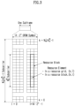
- 4-octet LBT failure MAC CE and SL LBT failure MAC CE may be identified by a MAC subheader with a specific LCID. As shown in (b) of Fig. 12 , the size of the 4-octet LBT failure MAC CE is fixed and can be composed of 4 octets including 32 C fields.
- the UCID value for UL-SCH may be defined as shown in Table 10 below. [Table 10] Codepoint/Index LCID value 42 SL LBT failure (4 Octet) 43 SL LBT failure (1 Octet) 48 UL LBT failure (4 Octet) 49 UL LBT failure (1 Octet)
- the highest 'ServCellIndex' of the serving cell of the MAC entity where the LBT failure is detected is less than 8, the single octet format is used, otherwise the four octet format may be used.
- Ci may be set to 1. Otherwise, Ci may be set to 0.
- embodiment 1 or embodiment 2 may depend on the SL mode or the serving cell where SL transmission is performed. For example, embodiment 1 may be used in SL mode 1, and embodiment 2 may be used in SL mode 2. Embodiment 1 may be used in a serving cell where both UL and SL transmissions are allowed, and embodiment 2 may be used in a serving cell. In this case, only SL transmission may be allowed, and UL transmission may not be allowed.
- the UE may transmit a PUCCH allocated for SR or trigger a RACH.
- the UE may transmit an LBT failure MAC CE or SL LBT failure MAC CE to the base station in UL using UL-SCH resources.
- the base station may perform one of the alternatives described below.
- the previous SL resource pool in which the LBT failure was reported in the aforementioned step may be changed to a new SL resource pool in RRC reset.
- the base station may indicate a new SL resource pool via DCI format 3_0, DCI format 3_x, or DL MAC CE.
- the UE receiving the indication may change the existing SL resource pool to the new SL resource pool.
- DCI format 3_0 or DCI format 3_x may include an SL resource pool index set for a new SL resource pool.
- Different SL resource pools of a cell may be configured with different SL resource pool indices unique to the cell or UE.
- the UE may autonomously change the old SL resource pool to the new SL resource pool immediately after SR, RACH transmission or MAC CE transmission or immediately after detection of consecutive LBT failures.
- the new SL resource pool may be the default SL resource pool configured by the base station or the SL resource pool of the initial SL BWP associated with the initial UL BWP.
- a previous SL BWP for which an LBT failure was reported in the above-described steps may be changed to a new SL BWP in RRC reconfiguration.
- the base station may indicate a new SL BWP via DCI format 3_0, DCI format 3_x or DL MAC CE.
- a terminal receiving the indication may change the previous SL BWP to the new SL BWP.
- DCI format 3_0 or 3_x may include an SL BWP indicator set for a new SL BWP.
- Different SL BWPs in a cell may be configured with different SL BWP indicator values that are unique to the cell or UE.
- the UE may autonomously change the previous SL BWP to a new SL BWP immediately after an SR, RACH transmission or a MAC CE transmission or immediately after detection of consecutive LBT failures.
- the new SL BWP may be either the default SL BWP configured by the base station or the SL BWP linked to the initial UL BWP.
- a previous SL RB set for which LBT failure was reported in the aforementioned step may be changed to a new SL RB set in RRC reconfiguration.
- the base station may indicate a new SL RB set via DCI format 3_0, DCI format 3_x or DL MAC CE.
- the terminal receiving the indication may change the previous SL RB set to the new SL RB set.
- DCI format 3_0 or DCI format 3_x may include an RB set index configured for a new SL RB set. Different RB sets of a cell may be configured with different RB set indices that are unique to the cell or UE.
- the UE may autonomously change the previous SL RB set to a new SL RB set immediately after an SR, RACH transmission or a MAC CE transmission or immediately after detection of consecutive LBT failures.
- the new SL RB set may be the default SL RB set configured by the base station or the SL RB set of the initial SL BWP associated with the initial UL BWP.
- the previous cell where the LBT failure was reported in the aforementioned step may be changed to a new cell in RRC reconfiguration.
- the base station may indicate a new cell via DCI format 3_0, DCI format 3_x or DL MAC CE.
- the terminal receiving the indication may change the existing cell to the new cell.
- DCI format 3_0 or 3_x may include a cell index set for a new cell.
- the UE may autonomously change the existing cell to a new cell immediately after SR, RACH transmission or MAC CE transmission or immediately after detection of consecutive LBT failures.
- the new cell may be the default cell configured by the base station or the cell of the initial SL BWP associated with the initial UL BWP.
- 'lbt-FailureInstanceMaxCount' for consistent LBT failure detection may be configured with different values for different alternatives.
- 'lbt-FailureDetectionTimer' for consistent LBT failure detection may be configured with different values for different alternatives.
- the base station may configure different 'lbt-FailureInstanceMaxCount' values for different alternatives.
- the 'lbt-FailureInstanceMaxCount' value for Alternative A may be lower than the 'lbt-FailureInstanceMaxCount' value for Alternative B.
- the base station may configure different 'lbt-FailureDetectionTimer' values for different alternatives such that the 'lbt-FailureDetectionTimer' value for Alternative D may be lower than the 'lbt-FailureDetectionTimer' value for Alternative B.
- 'lbt-FailureInstanceMaxCount' for consistent LBT failure detection and 'lbt-FailureDetectionTimer' for consistent LBT failure detection may be configured with different values for SL mode 1 (i.e., SL resource allocation mode 1) and SL mode 2 (i.e., SL resource allocation mode 2) respectively.
- SL mode 1 For SL mode 1, the parameters described above may be used for SR reporting.
- SL mode 2 the parameters described above may be used for resource reselection. Additionally or alternatively, SR may be triggered due to consistent LBT errors in the steps described above for both SL mode 1 and SL mode 2.
- the UE may detect a collision between a PUCCH transmission and a sidelink transmission for a triggered SR (S1050).
- a UE may prioritize PUCCH transmission for SR over sidelink transmission if the following conditions are satisfied (S1060).
- the UE may prioritize PUCCH transmission for SR over sidelink transmission according to the method described below.
- the base station may indicate the UE whether SR triggered for LBT failure may be prioritized over sidelink transmissions.
- a UE may lower the priority of PUCCH transmissions for other SRs over sidelink transmissions if the SR is not triggered for LBT failure MAC CE or SL LBT failure MAC CE.
- the UE may drop the sidelink transmission. And, if the sidelink transmission does not collide with any SR, the UE may perform the sidelink transmission using either the reserved resources or the received resources.
- the base station may transmit a CRC scrambled PDCCH with a C-RNTI for a UL grant to the UE, and the UE may transmit a (SL) LBT failure MAC CE to the base station.
- the base station may transmit a PDCCH including a new cell index, SL BWP indicator, etc. to the UE as described above (S1075).
- the UE may change the SL BWP or cell based on the PDCCH (S1080).
- the base station may transmit a PDCCH CRC scrambled by SL-RNTI or SLCS-RNTI to the terminal (S1085).
- the UE may perform PSCCH/PSCCH transmission with the receiving UE based on the PDCCH (S1090).
- the UE may prioritize the PUSCH carrying the LBT failure MAC CE or the SL LBT failure MAC CE in the logical channel prioritization of the MAC entity for transmitting the MAC CE in the MAC PDU in the uplink as described below.
- a UE may prioritize a PUSCH carrying a MAC PDU containing an LBT failure MAC CE or a SL LBT failure MAC CE over sidelink transmission.
- sidelink transmission, grant and resource may be replaced with uplink transmission, grant and resource.
- the UE when a base station allocates an SL grant to a UE performing SL transmission in an unlicensed band, the UE can report consistent LBT failure for SL transmission to the base station according to the present disclosure.
- FIG. 13 illustrates a block diagram of a wireless communication device according to an embodiment of the present disclosure.
- a first wireless device 100 and a second wireless device 200 may transmit and receive a wireless signal through a variety of radio access technologies (e.g., LTE, NR).
- radio access technologies e.g., LTE, NR.
- a first wireless device 100 may include one or more processors 102 and one or more memories 104 and may additionally include one or more transceivers 106 and/or one or more antennas 108.
- a processor 102 may control a memory 104 and/or a transceiver 106 and may be configured to implement description, functions, procedures, proposals, methods and/or operation flow charts disclosed in the present disclosure.
- the processor 102 may process the information in the memory 104 to generate first information/signal and then transmit a wireless signal including the first information/signal through the transceiver 106. Additionally, the processor 102 may receive a wireless signal including the second information/signal through the transceiver 106 and then store information obtained from signal processing of the second information/signal in the memory 104.
- a memory 104 may be connected to a processor 102 and may store a variety of information related to an operation of a processor 102.
- a memory 104 may store a software code including commands for performing all or part of processes controlled by a processor 102 or for performing description, functions, procedures, proposals, methods and/or operation flow charts disclosed in the present disclosure.
- a processor 102 and a memory 104 may be part of a communication modem/circuit/chip designed to implement a wireless communication technology (e.g., LTE, NR).
- a transceiver 106 may be connected to a processor 102 and may transmit and/or receive a wireless signal through one or more antennas 108.
- a transceiver 106 may include a transmitter and/or a receiver.
- a transceiver 106 may be used together with a RF (Radio Frequency) unit.
- a wireless device may mean a communication modem/circuit/chip.
- a second wireless device 200 may include one or more processors 202 and one or more memories 204 and may additionally include one or more transceivers 206 and/or one or more antennas 208.
- a processor 202 may control a memory 204 and/or a transceiver 206 and may be configured to implement description, functions, procedures, proposals, methods and/or operation flows charts disclosed in the present disclosure.
- a processor 202 may generate third information/signal by processing information in a memory 204, and then transmit a wireless signal including third information/signal through a transceiver 206.
- a processor 202 may receive a wireless signal including fourth information/signal through a transceiver 206, and then store information obtained by signal processing of fourth information/signal in a memory 204.
- a memory 204 may be connected to a processor 202 and may store a variety of information related to an operation of a processor 202.
- a memory 204 may store a software code including commands for performing all or part of processes controlled by a processor 202 or for performing description, functions, procedures, proposals, methods and/or operation flow charts disclosed in the present disclosure.
- a processor 202 and a memory 204 may be part of a communication modem/circuit/chip designed to implement a wireless communication technology (e.g., LTE, NR).
- a transceiver 206 may be connected to a processor 202 and may transmit and/or receive a wireless signal through one or more antennas 208.
- a transceiver 206 may include a transmitter and/or a receiver.
- a transceiver 206 may be used together with a RF unit.
- a wireless device may mean a communication modem/circuit/chip.
- one or more protocol layers may be implemented by one or more processors 102, 202.
- one or more processors 102, 202 may implement one or more layers (e.g., a functional layer such as PHY, MAC, RLC, PDCP, RRC, SDAP).
- One or more processors 102, 202 may generate one or more PDUs (Protocol Data Unit) and/or one or more SDUs (Service Data Unit) according to description, functions, procedures, proposals, methods and/or operation flow charts included in the present disclosure.
- PDUs Protocol Data Unit
- SDUs Service Data Unit
- One or more processors 102, 202 may generate a message, control information, data or information according to description, functions, procedures, proposals, methods and/or operation flow charts disclosed in the present disclosure.
- One or more processors 102, 202 may generate a signal (e.g., a baseband signal) including a PDU, a SDU, a message, control information, data or information according to functions, procedures, proposals and/or methods disclosed in the present disclosure to provide it to one or more transceivers 106, 206.
- a signal e.g., a baseband signal
- One or more processors 102, 202 may receive a signal (e.g., a baseband signal) from one or more transceivers 106, 206 and obtain a PDU, a SDU, a message, control information, data or information according to description, functions, procedures, proposals, methods and/or operation flow charts disclosed in the present disclosure.
- a signal e.g., a baseband signal
- One or more processors 102, 202 may be referred to as a controller, a micro controller, a micro processor or a micro computer.
- One or more processors 102, 202 may be implemented by a hardware, a firmware, a software, or their combination.
- one or more ASICs Application Specific Integrated Circuit
- one or more DSPs Digital Signal Processor
- one or more DSPDs Digital Signal Processing Device
- one or more PLDs Programmable Logic Device
- FPGAs Field Programmable Gate Arrays
- Description, functions, procedures, proposals, methods and/or operation flow charts disclosed in the present disclosure may be implemented by using a firmware or a software and a firmware or a software may be implemented to include a module, a procedure, a function, etc.
- a firmware or a software configured to perform description, functions, procedures, proposals, methods and/or operation flow charts disclosed in the present disclosure may be included in one or more processors 102, 202 or may be stored in one or more memories 104, 204 and driven by one or more processors 102, 202.
- Description, functions, procedures, proposals, methods and/or operation flow charts disclosed in the present disclosure may be implemented by using a firmware or a software in a form of a code, a command and/or a set of commands.
- One or more memories 104, 204 may be connected to one or more processors 102, 202 and may store data, a signal, a message, information, a program, a code, an instruction and/or a command in various forms.
- One or more memories 104, 204 may be configured with ROM, RAM, EPROM, a flash memory, a hard drive, a register, a cash memory, a computer readable storage medium and/or their combination.
- One or more memories 104, 204 may be positioned inside and/or outside one or more processors 102, 202.
- one or more memories 104, 204 may be connected to one or more processors 102, 202 through a variety of technologies such as a wire or wireless connection.
- One or more transceivers 106, 206 may transmit user data, control information, a wireless signal/channel, etc. mentioned in methods and/or operation flow charts, etc. of the present disclosure to one or more other devices.
- One or more transceivers 106, 206 may receiver user data, control information, a wireless signal/channel, etc. mentioned in description, functions, procedures, proposals, methods and/or operation flow charts, etc. disclosed in the present disclosure from one or more other devices.
- one or more transceivers 106, 206 may be connected to one or more processors 102, 202 and may transmit and receive a wireless signal.
- one or more processors 102, 202 may control one or more transceivers 106, 206 to transmit user data, control information or a wireless signal to one or more other devices.
- one or more processors 102, 202 may control one or more transceivers 106, 206 to receive user data, control information or a wireless signal from one or more other devices.
- one or more transceivers 106, 206 may be connected to one or more antennas 108, 208 and one or more transceivers 106, 206 may be configured to transmit and receive user data, control information, a wireless signal/channel, etc. mentioned in description, functions, procedures, proposals, methods and/or operation flow charts, etc.
- one or more antennas may be a plurality of physical antennas or a plurality of logical antennas (e.g., an antenna port).
- One or more transceivers 106, 206 may convert a received wireless signal/channel, etc. into a baseband signal from a RF band signal to process received user data, control information, wireless signal/channel, etc. by using one or more processors 102, 202.
- One or more transceivers 106, 206 may convert user data, control information, a wireless signal/channel, etc. which are processed by using one or more processors 102, 202 from a baseband signal to a RF band signal. Therefore, one or more transceivers 106, 206 may include an (analogue) oscillator and/or a filter.
- Embodiments described above are that elements and features of the present disclosure are combined in a predetermined form. Each element or feature should be considered to be optional unless otherwise explicitly mentioned. Each element or feature may be implemented in a form that it is not combined with other element or feature.
- an embodiment of the present disclosure may include combining a part of elements and/or features. An order of operations described in embodiments of the present disclosure may be changed. Some elements or features of one embodiment may be included in other embodiment or may be substituted with a corresponding element or a feature of other embodiment. It is clear that an embodiment may include combining claims without an explicit dependency relationship in claims or may be included as a new claim by amendment after application.
- a scope of the present disclosure includes software or machine-executable commands (e.g., an operating system, an application, a firmware, a program, etc.) which execute an operation according to a method of various embodiments in a device or a computer and a non-transitory computer-readable medium that such a software or a command, etc. are stored and are executable in a device or a computer.
- a command which may be used to program a processing system performing a feature described in the present disclosure may be stored in a storage medium or a computer-readable storage medium and a feature described in the present disclosure may be implemented by using a computer program product including such a storage medium.
- a storage medium may include a high-speed random-access memory such as DRAM, SRAM, DDR RAM or other random-access solid state memory device, but it is not limited thereto, and it may include a nonvolatile memory such as one or more magnetic disk storage devices, optical disk storage devices, flash memory devices or other nonvolatile solid state storage devices.
- a memory optionally includes one or more storage devices positioned remotely from processor(s).
- a memory or alternatively, nonvolatile memory device(s) in a memory include a non-transitory computer-readable storage medium.
- a feature described in the present disclosure may be stored in any one of machine-readable mediums to control a hardware of a processing system and may be integrated into a software and/or a firmware which allows a processing system to interact with other mechanism utilizing a result from an embodiment of the present disclosure.
- a software or a firmware may include an application code, a device driver, an operating system and an execution environment/container, but it is not limited thereto.
- a wireless communication technology implemented in a wireless device 100, 200 of the present disclosure may include Narrowband Internet of Things for a low-power communication as well as LTE, NR and 6G.
- an NB-IoT technology may be an example of a LPWAN(Low Power Wide Area Network) technology, may be implemented in a standard of LTE Cat NB1 and/or LTE Cat NB2, etc. and is not limited to the above-described name.
- a wireless communication technology implemented in a wireless device 100, 200 of the present disclosure may perform a communication based on a LTE-M technology.
- a LTE-M technology may be an example of a LPWAN technology and may be referred to a variety of names such as an eMTC (enhanced Machine Type Communication), etc.
- an LTE-M technology may be implemented in at least any one of various standards including 1) LTE CAT 0, 2) LTE Cat M1, 3) LTE Cat M2, 4) LTE non-BL(non-Bandwidth Limited), 5) LTE-MTC, 6) LTE Machine Type Communication, and/or 7) LTE M and so on and it is not limited to the above-described name.
- a wireless communication technology implemented in a wireless device 100, 200 of the present disclosure may include at least any one of a ZigBee, a Bluetooth and a low power wide area network (LPWAN) considering a low-power communication and it is not limited to the above-described name.
- a ZigBee technology may generate PAN(personal area networks) related to a small/low-power digital communication based on a variety of standards such as IEEE 802.15.4, etc. and may be referred to as a variety of names.
- a method proposed by the present disclosure is mainly described based on an example applied to 3GPP LTE/LTE-A, 5G system, but may be applied to various wireless communication systems other than the 3GPP LTE/LTE-A, 5G system.
Landscapes
- Engineering & Computer Science (AREA)
- Computer Networks & Wireless Communication (AREA)
- Signal Processing (AREA)
- Mobile Radio Communication Systems (AREA)
Applications Claiming Priority (2)
| Application Number | Priority Date | Filing Date | Title |
|---|---|---|---|
| US202263335203P | 2022-04-26 | 2022-04-26 | |
| PCT/KR2023/005709 WO2023211158A1 (fr) | 2022-04-26 | 2023-04-26 | Procédé et dispositif permettant de réaliser une communication de liaison latérale dans un système de communication sans fil |
Publications (2)
| Publication Number | Publication Date |
|---|---|
| EP4518532A1 true EP4518532A1 (fr) | 2025-03-05 |
| EP4518532A4 EP4518532A4 (fr) | 2026-04-15 |
Family
ID=88519188
Family Applications (1)
| Application Number | Title | Priority Date | Filing Date |
|---|---|---|---|
| EP23796801.1A Pending EP4518532A4 (fr) | 2022-04-26 | 2023-04-26 | Procédé et dispositif permettant de réaliser une communication de liaison latérale dans un système de communication sans fil |
Country Status (5)
| Country | Link |
|---|---|
| US (1) | US20250294586A1 (fr) |
| EP (1) | EP4518532A4 (fr) |
| KR (1) | KR20250003822A (fr) |
| CN (1) | CN119138082A (fr) |
| WO (1) | WO2023211158A1 (fr) |
Families Citing this family (1)
| Publication number | Priority date | Publication date | Assignee | Title |
|---|---|---|---|---|
| KR20240161515A (ko) * | 2023-05-04 | 2024-11-12 | 삼성전자주식회사 | 무선 통신 시스템에서 리소스 블록 집합을 결정하기 위한 방법 및 장치 |
Family Cites Families (5)
| Publication number | Priority date | Publication date | Assignee | Title |
|---|---|---|---|---|
| WO2020198584A1 (fr) * | 2019-03-27 | 2020-10-01 | Apple Inc. | Gestion de défaillance d'écoute avant de parler de liaison montante |
| EP4005278B1 (fr) * | 2019-07-25 | 2024-06-05 | FG Innovation Company Limited | Procédé et appareil de gestion d'échec de protocole lbt |
| US11576211B2 (en) * | 2019-12-19 | 2023-02-07 | Qualcomm Incorporated | Autonomous sidelink over unlicensed band |
| US12369190B2 (en) * | 2020-04-20 | 2025-07-22 | Lg Electronics Inc. | Method and apparatus for performing LBT procedures by UE in wireless communication system |
| PL4427537T3 (pl) * | 2021-11-03 | 2025-09-22 | Interdigital Patent Holdings, Inc. | Uporczywe niepowodzenie nasłuchu przed rozmową dla łącza pobocznego |
-
2023
- 2023-04-26 CN CN202380036516.9A patent/CN119138082A/zh active Pending
- 2023-04-26 KR KR1020247037817A patent/KR20250003822A/ko active Pending
- 2023-04-26 US US18/860,433 patent/US20250294586A1/en active Pending
- 2023-04-26 EP EP23796801.1A patent/EP4518532A4/fr active Pending
- 2023-04-26 WO PCT/KR2023/005709 patent/WO2023211158A1/fr not_active Ceased
Also Published As
| Publication number | Publication date |
|---|---|
| KR20250003822A (ko) | 2025-01-07 |
| WO2023211158A1 (fr) | 2023-11-02 |
| US20250294586A1 (en) | 2025-09-18 |
| CN119138082A (zh) | 2024-12-13 |
| EP4518532A4 (fr) | 2026-04-15 |
Similar Documents
| Publication | Publication Date | Title |
|---|---|---|
| US11824666B2 (en) | Method and apparatus for transmitting and receiving control information in wireless communication system | |
| EP4383614A1 (fr) | Procédé et dispositif de transmission et de réception de pucch dans un système de communication sans fil | |
| US20240365337A1 (en) | Method and device for transmitting/receiving control information in wireless communication system | |
| EP4518538A1 (fr) | Procédé et dispositif de mise en oeuvre de communication de liaison latérale dans un système de communication sans fil | |
| EP4518532A1 (fr) | Procédé et dispositif permettant de réaliser une communication de liaison latérale dans un système de communication sans fil | |
| EP4518530A1 (fr) | Procédé et appareil permettant de réaliser une communication de liaison latérale dans un système de communication sans fil | |
| EP4518529A1 (fr) | Procédé et appareil permettant de réaliser une communication de liaison latérale dans un système de communication sans fil | |
| EP4518555A1 (fr) | Procédé et dispositif de réalisation d'une communication de liaison latérale dans un système de communication sans fil | |
| EP4518473A1 (fr) | Procédé et dispositif permettant d'effectuer une communication de liaison latérale dans un système de communication sans fil | |
| EP4518536A1 (fr) | Procédé et dispositif permettant de réaliser une communication de liaison latérale dans un système de communication sans fil | |
| US20250294584A1 (en) | Method and device for sidelink transmission or reception in wireless communication system | |
| EP4271073B1 (fr) | Procédé et appareil pour effectuer une communication de liaison latérale dans un système de communication sans fil | |
| EP4478637A1 (fr) | Procédé et dispositif de transmission et de réception en liaison montante dans un système de communication sans fil | |
| EP4518531A1 (fr) | Procédé et dispositif pour la réalisation d'une communication de liaison latérale dans un système de communication sans fil | |
| EP4518533A1 (fr) | Procédé et appareil permettant de réaliser une communication de liaison latérale dans un système de communication sans fil | |
| EP4518556A1 (fr) | Procédé et dispositif permettant de réaliser une communication de liaison latérale dans un système de communication sans fil | |
| EP4518534A1 (fr) | Procédé et dispositif permettant de réaliser une communication de liaison latérale dans un système de communication sans fil | |
| EP4518537A1 (fr) | Procédé et dispositif d'exécution d'une communication en liaison latérale dans un système de communication sans fil | |
| EP4694355A1 (fr) | Procédé et dispositif pour effectuer une procédure de relais d'ue à ue dans un système de communication sans fil | |
| EP4462707A1 (fr) | Procédé et appareil de transmission et de réception d'information de commande dans un système de communication sans fil |
Legal Events
| Date | Code | Title | Description |
|---|---|---|---|
| STAA | Information on the status of an ep patent application or granted ep patent |
Free format text: STATUS: THE INTERNATIONAL PUBLICATION HAS BEEN MADE |
|
| PUAI | Public reference made under article 153(3) epc to a published international application that has entered the european phase |
Free format text: ORIGINAL CODE: 0009012 |
|
| STAA | Information on the status of an ep patent application or granted ep patent |
Free format text: STATUS: REQUEST FOR EXAMINATION WAS MADE |
|
| 17P | Request for examination filed |
Effective date: 20241121 |
|
| AK | Designated contracting states |
Kind code of ref document: A1 Designated state(s): AL AT BE BG CH CY CZ DE DK EE ES FI FR GB GR HR HU IE IS IT LI LT LU LV MC ME MK MT NL NO PL PT RO RS SE SI SK SM TR |
|
| DAV | Request for validation of the european patent (deleted) | ||
| DAX | Request for extension of the european patent (deleted) | ||
| REG | Reference to a national code |
Ref country code: DE Ref legal event code: R079 Free format text: PREVIOUS MAIN CLASS: H04W0072250000 Ipc: H04W0074080800 |
|
| A4 | Supplementary search report drawn up and despatched |
Effective date: 20260313 |
|
| RIC1 | Information provided on ipc code assigned before grant |
Ipc: H04W 74/0808 20240101AFI20260309BHEP Ipc: H04L 1/1812 20230101ALI20260309BHEP Ipc: H04W 24/08 20090101ALI20260309BHEP Ipc: H04L 1/1822 20230101ALI20260309BHEP Ipc: H04W 92/18 20090101ALN20260309BHEP Ipc: H04W 72/21 20230101ALN20260309BHEP Ipc: H04W 72/23 20230101ALN20260309BHEP Ipc: H04W 72/40 20230101ALN20260309BHEP |