EP4520237A1 - Saugkopf mit durchbrochenem stützring - Google Patents
Saugkopf mit durchbrochenem stützring Download PDFInfo
- Publication number
- EP4520237A1 EP4520237A1 EP24198255.2A EP24198255A EP4520237A1 EP 4520237 A1 EP4520237 A1 EP 4520237A1 EP 24198255 A EP24198255 A EP 24198255A EP 4520237 A1 EP4520237 A1 EP 4520237A1
- Authority
- EP
- European Patent Office
- Prior art keywords
- support ring
- air
- suction head
- bearing
- cooling circuit
- Prior art date
- Legal status (The legal status is an assumption and is not a legal conclusion. Google has not performed a legal analysis and makes no representation as to the accuracy of the status listed.)
- Pending
Links
Images



Classifications
-
- A—HUMAN NECESSITIES
- A47—FURNITURE; DOMESTIC ARTICLES OR APPLIANCES; COFFEE MILLS; SPICE MILLS; SUCTION CLEANERS IN GENERAL
- A47L—DOMESTIC WASHING OR CLEANING; SUCTION CLEANERS IN GENERAL
- A47L9/00—Details or accessories of suction cleaners, e.g. mechanical means for controlling the suction or for effecting pulsating action; Storing devices specially adapted to suction cleaners or parts thereof; Carrying-vehicles specially adapted for suction cleaners
- A47L9/02—Nozzles
- A47L9/04—Nozzles with driven brushes or agitators
-
- A—HUMAN NECESSITIES
- A46—BRUSHWARE
- A46B—BRUSHES
- A46B13/00—Brushes with driven brush bodies or carriers
- A46B13/001—Cylindrical or annular brush bodies
-
- A—HUMAN NECESSITIES
- A46—BRUSHWARE
- A46B—BRUSHES
- A46B13/00—Brushes with driven brush bodies or carriers
- A46B13/02—Brushes with driven brush bodies or carriers power-driven carriers
-
- A—HUMAN NECESSITIES
- A47—FURNITURE; DOMESTIC ARTICLES OR APPLIANCES; COFFEE MILLS; SPICE MILLS; SUCTION CLEANERS IN GENERAL
- A47L—DOMESTIC WASHING OR CLEANING; SUCTION CLEANERS IN GENERAL
- A47L5/00—Structural features of suction cleaners
- A47L5/12—Structural features of suction cleaners with power-driven air-pumps or air-compressors, e.g. driven by motor vehicle engine vacuum
- A47L5/22—Structural features of suction cleaners with power-driven air-pumps or air-compressors, e.g. driven by motor vehicle engine vacuum with rotary fans
- A47L5/28—Suction cleaners with handles and nozzles fixed on the casings, e.g. wheeled suction cleaners with steering handle
- A47L5/30—Suction cleaners with handles and nozzles fixed on the casings, e.g. wheeled suction cleaners with steering handle with driven dust-loosening tools, e.g. rotating brushes
-
- A—HUMAN NECESSITIES
- A47—FURNITURE; DOMESTIC ARTICLES OR APPLIANCES; COFFEE MILLS; SPICE MILLS; SUCTION CLEANERS IN GENERAL
- A47L—DOMESTIC WASHING OR CLEANING; SUCTION CLEANERS IN GENERAL
- A47L7/00—Suction cleaners adapted for additional purposes; Tables with suction openings for cleaning purposes; Containers for cleaning articles by suction; Suction cleaners adapted to cleaning of brushes; Suction cleaners adapted to taking-up liquids
- A47L7/0085—Suction cleaners adapted for additional purposes; Tables with suction openings for cleaning purposes; Containers for cleaning articles by suction; Suction cleaners adapted to cleaning of brushes; Suction cleaners adapted to taking-up liquids adapted for special purposes not related to cleaning
-
- A—HUMAN NECESSITIES
- A47—FURNITURE; DOMESTIC ARTICLES OR APPLIANCES; COFFEE MILLS; SPICE MILLS; SUCTION CLEANERS IN GENERAL
- A47L—DOMESTIC WASHING OR CLEANING; SUCTION CLEANERS IN GENERAL
- A47L9/00—Details or accessories of suction cleaners, e.g. mechanical means for controlling the suction or for effecting pulsating action; Storing devices specially adapted to suction cleaners or parts thereof; Carrying-vehicles specially adapted for suction cleaners
- A47L9/02—Nozzles
- A47L9/04—Nozzles with driven brushes or agitators
- A47L9/0405—Driving means for the brushes or agitators
- A47L9/0411—Driving means for the brushes or agitators driven by electric motor
-
- A—HUMAN NECESSITIES
- A47—FURNITURE; DOMESTIC ARTICLES OR APPLIANCES; COFFEE MILLS; SPICE MILLS; SUCTION CLEANERS IN GENERAL
- A47L—DOMESTIC WASHING OR CLEANING; SUCTION CLEANERS IN GENERAL
- A47L9/00—Details or accessories of suction cleaners, e.g. mechanical means for controlling the suction or for effecting pulsating action; Storing devices specially adapted to suction cleaners or parts thereof; Carrying-vehicles specially adapted for suction cleaners
- A47L9/02—Nozzles
- A47L9/04—Nozzles with driven brushes or agitators
- A47L9/0455—Bearing means therefor
-
- A—HUMAN NECESSITIES
- A47—FURNITURE; DOMESTIC ARTICLES OR APPLIANCES; COFFEE MILLS; SPICE MILLS; SUCTION CLEANERS IN GENERAL
- A47L—DOMESTIC WASHING OR CLEANING; SUCTION CLEANERS IN GENERAL
- A47L9/00—Details or accessories of suction cleaners, e.g. mechanical means for controlling the suction or for effecting pulsating action; Storing devices specially adapted to suction cleaners or parts thereof; Carrying-vehicles specially adapted for suction cleaners
- A47L9/02—Nozzles
- A47L9/04—Nozzles with driven brushes or agitators
- A47L9/0461—Dust-loosening tools, e.g. agitators, brushes
- A47L9/0466—Rotating tools
- A47L9/0477—Rolls
-
- A—HUMAN NECESSITIES
- A47—FURNITURE; DOMESTIC ARTICLES OR APPLIANCES; COFFEE MILLS; SPICE MILLS; SUCTION CLEANERS IN GENERAL
- A47L—DOMESTIC WASHING OR CLEANING; SUCTION CLEANERS IN GENERAL
- A47L9/00—Details or accessories of suction cleaners, e.g. mechanical means for controlling the suction or for effecting pulsating action; Storing devices specially adapted to suction cleaners or parts thereof; Carrying-vehicles specially adapted for suction cleaners
- A47L9/28—Installation of the electric equipment, e.g. adaptation or attachment to the suction cleaner; Controlling suction cleaners by electric means
- A47L9/2889—Safety or protection devices or systems, e.g. for prevention of motor over-heating or for protection of the user
-
- A—HUMAN NECESSITIES
- A46—BRUSHWARE
- A46B—BRUSHES
- A46B2200/00—Brushes characterized by their functions, uses or applications
- A46B2200/30—Brushes for cleaning or polishing
- A46B2200/3033—Household brush, i.e. brushes for cleaning in the house or dishes
Definitions
- the present invention relates to the field of vacuum cleaners equipped with a suction head for vacuuming dust and waste present on a surface to be cleaned.
- Vacuum cleaners equipped with a suction head are well known on the market, allowing you to clean surfaces by suction to remove dust and debris from them.
- the surface to be vacuumed can, for example, be tiles, parquet, laminate, carpet, or a rug.
- a suction head comprises, in a known manner, a main body comprising a sole provided with a lower face and a suction mouth opening into the lower face of the sole.
- the lower face of the sole is intended to be positioned adjacent to the surface to be vacuumed during use of the suction head.
- the first bearing When operating such a suction head where the rotating brush is rotated, the first bearing tends to heat up due to the rotational speed of the first support ring and the proximity of the drive motor, which can adversely affect the operation of the first bearing and thus the reliability of the suction head.
- the present invention aims to remedy all or part of these drawbacks.
- the technical problem underlying the invention consists in particular in providing a suction head, provided with a rotating brush and a brush drive motor, which is of simple and economical structure, while ensuring satisfactory cooling of a brush bearing located near the brush drive motor.
- the support ring comprises at least one through hole which opens respectively into the first and second axial faces of the support ring, the suction head being configured such that, when the suction head is in the use configuration and in particular when a vacuum is generated in the suction chamber and/or when the drive motor is running, an air flow is able to flow through the at least one through hole and for example from the first axial face of the support ring to the second axial face of the support ring.
- Such a configuration of the support ring, and in particular the presence of the at least one through hole ensures, when a depression is generated in the suction chamber, the flow of an air flow through the at least one through hole, and therefore cooling, by thermal conduction, of the support ring and the bearing located near the drive motor.
- Such cooling makes it possible to limit the heating of the bearing and thus to preserve its integrity, and therefore to confer a increased reliability of the suction head according to the present invention, and also to be able to use a bearing of smaller dimensions and thus to reduce the radial size of the rotating brush.
- the suction head may further have one or more of the following features, taken alone or in combination.
- the at least one through hole is fluidically connected to the suction chamber.
- the support ring is attached to an end portion of the brush body which is located on the drive motor side.
- the brush body comprises a first end portion at least partially delimiting the motor housing, and a second end portion which is located opposite the first end portion, the support ring being fixed to the first end portion of the brush body and being configured to support said first end portion.
- the support ring is arranged in the first end portion of the brush body.
- the at least one through hole opens into the motor housing.
- the bearing is a rolling bearing, and comprises an inner ring which is fixed to the bearing support and which extends around the bearing support, and an outer ring which is fixed to the support ring, the support ring extending around the outer ring of the bearing.
- the presence of the at least one through hole ensures in particular cooling of the outer ring of the bearing.
- the suction head comprises an additional support ring fixed, for example by gluing or welding, to the second end portion of the brush body and configured to support the second end portion of the brush body.
- an additional support ring fixed, for example by gluing or welding, to the second end portion of the brush body and configured to support the second end portion of the brush body.
- the drive motor is arranged axially between the support ring and the additional support ring.
- the drive motor is closer to the support ring than to the additional support ring.
- the drive motor is arranged axially between the support ring and a median vertical plane of the suction head. Hence the need to cool the support ring, which heats up more quickly than the additional support ring due to its proximity to the drive motor.
- the suction head comprises an additional bearing, such as a rolling bearing and for example a ball bearing, configured to guide the additional support ring in rotation.
- an additional bearing such as a rolling bearing and for example a ball bearing, configured to guide the additional support ring in rotation.
- the bearing support, the bearing and the support ring are arranged substantially coaxially with the central longitudinal axis of the brush body.
- the suction head comprises an air circulation cooling circuit delimited at least in part by the support ring and fluidically connected to the suction chamber, the suction head being configured such that, when a negative pressure is generated in the suction chamber, air is sucked into the air circulation cooling circuit from outside the rotating brush and is circulated in the air circulation cooling circuit.
- an air circulation cooling circuit ensures further increased cooling of the bearing, and in particular of the outer ring of the bearing, due to the fact that the air circulating in the air circulation cooling circuit flows in the vicinity of the support ring.
- the circulation cooling circuit air is delimited at least in part also by the brush body.
- the air circulation cooling circuit comprises at least one air intake opening through which air is adapted to be sucked into the air circulation cooling circuit and at least one air discharge opening through which air flowing into the air circulation cooling circuit is adapted to be discharged from the air circulation cooling circuit, the at least one air discharge opening being formed by the at least one through hole provided on the support ring.
- the suction head is configured such that the air sucked into the air circulation cooling circuit is discharged from the air circulation cooling circuit via the at least one through hole provided on the support ring.
- the at least one air intake opening is provided on a side wall of the main body, and for example on a side wall of the main body located on the side of the bearing support and advantageously to which the bearing support is fixed.
- the at least one air intake opening is oriented substantially axially, i.e. substantially parallel to the central longitudinal axis of the brush body.
- Such an orientation of the at least one air intake opening limits the risks of dust being sucked in by the air circulation cooling circuit, which makes it possible to significantly reduce the risks of fouling, or even clogging, of the air circulation cooling circuit and therefore to ensure optimal cooling of the bearing and also of the drive motor when the air circulation cooling circuit is delimited in part by the drive motor.
- the drive motor comprises a motor housing.
- the drive motor further comprises a rotor and a stator which are housed in the motor housing.
- the circulation cooling circuit air is delimited at least in part by the drive motor such that, when a vacuum is generated in the suction chamber, the air circulating in the air circulation cooling circuit flows into or near the drive motor.
- the air circulation cooling circuit is delimited at least in part by the support ring, the brush body and the drive motor.
- the air circulation cooling circuit comprises at least one air inlet opening provided on a peripheral wall of a motor housing of the drive motor and through which the air, circulated in the air circulation cooling circuit when a vacuum is generated in the suction chamber, is able to penetrate into the drive motor, and at least one air outlet opening provided on an end wall of the motor housing and through which the air, having penetrated into the drive motor via the at least one air inlet opening, is able to flow outside the drive motor.
- Such a configuration of the air circulation cooling circuit ensures cooling, by thermal conduction, of the drive motor, which makes it possible to preserve the integrity of the drive motor and to further limit the heating of the bearing.
- the at least one air inlet opening of the engine casing is oriented substantially radially and the at least one air outlet opening of the engine casing is oriented substantially axially.
- the suction head comprises a motor compartment which is fixed to the bearing support and which is arranged at least partly in the motor housing, the drive motor being arranged at least partly, and for example entirely, in the motor compartment.
- the air circulation cooling circuit comprises a first circuit portion which is partly delimited by the engine drive and a second circuit portion which is partly delimited by the motor compartment and the brush body and which is located downstream of the first circuit portion.
- the air circulation cooling circuit is configured such that, when a vacuum is generated in the suction chamber, the air, circulated in the air circulation cooling circuit, flows in the first circuit portion away from the support ring, and flows in the second circuit portion towards the support ring.
- the air circulation cooling circuit is configured such that, when a vacuum is generated in the suction chamber, the air, circulated in the first circuit portion, flows at least partly inside the drive motor, and such that the air, circulated in the second circuit portion, flows at least partly between the motor compartment and the brush body.
- the drive motor has a temperature much higher than that of the motor compartment.
- the air circulation cooling circuit is configured such that, when a vacuum is generated in the suction chamber, the air, circulated in the first circuit portion, flows into contact with the rotor and/or the stator of the drive motor, and for example into contact with the stator winding and/or the rotor winding.
- the first circuit portion is configured such that, when a vacuum is generated in the suction chamber, the air, flowing inside the drive motor, flows in a flow direction which is substantially parallel to the central longitudinal axis of the brush body.
- the air circulation cooling circuit is configured such that, when a depression is generated in the suction chamber, the air, circulated in the second circuit portion, flows substantially parallel to the central longitudinal axis of the brush body.
- the bearing support delimits an air flow duct which partly forms the air circulation cooling circuit, and for example partly the first circuit portion, the bearing extending around the air flow duct.
- the bearing support ensures cooling, by thermal conduction, of the bearing support and the bearing, and in particular of the outer ring of the bearing.
- the air flow duct is fluidically connected to the at least one air intake opening.
- the air flow duct extends substantially coaxially with the bearing.
- the engine compartment delimits an internal housing which is fluidically connected to the at least one air intake opening belonging to the air circulation cooling circuit, and in particular to the air flow duct delimited by the bearing support.
- the at least one air inlet opening provided on the engine casing, opens into the internal housing delimited by the engine compartment.
- the motor compartment and the brush body delimit a connecting chamber which is located axially opposite the support ring relative to the drive motor and which is configured to connect fluidly the first circuit portion to the second circuit portion.
- the at least one air outlet opening is fluidly connected to the connecting chamber.
- the engine compartment includes an engine cover extending around the drive motor and a cover support attached to the bearing support and configured to support the engine cover.
- the engine cover has an open end, and the cover support at least partially closes the open end of the engine cover.
- the motor cover comprises a tubular wall which extends around the drive motor and which is substantially coaxial with the motor axis of the drive motor, and an end wall located opposite the cover support and provided with a central opening through which the output shaft of the drive motor projects.
- the suction head comprises a damping element interposed axially between the drive motor and the hood support.
- the drive motor is located at a distance from the side walls of the main body, and in particular is axially offset relative to the side wall of the main body on which the bearing support is fixed. Such an arrangement of the drive motor ensures better balancing of the masses within the main body, and in particular around the central longitudinal axis.
- the support ring is rotationally fixed to the brush body, and the at least one through-hole provided on the support ring is delimited at least in part by at least one flow-guiding wall which is inclined relative to a central axis of the support ring and which is configured to generate a depression within the at least one through-hole when the drive motor is running and rotating the rotating brush.
- the support ring configuration increases the air flow in the cooling circuit by air circulation, and thus further promotes bearing cooling.
- the at least one flow guide wall forms a flow guide fin, also called a blade.
- the at least one flow guide wall has an axial dimension and a radial dimension which is smaller than the respective axial dimension.
- the at least one through hole provided on the support ring is delimited at least in part by two flow guide walls which are inclined relative to the central axis of the support ring and which are located opposite each other, the two flow guide walls delimiting at least in part the at least one through hole being configured to generate a depression within the at least one through hole when the drive motor is running.
- the support ring is rotationally fixed to the brush body, the support ring forms a turbine provided with flow guide vanes distributed around a central axis of the support ring, each pair of adjacent flow guide vanes partly delimiting a respective through hole, and the support ring, forming the turbine, is configured to generate a depression within the at least one through hole when the drive motor is running and rotating the rotating brush.
- the support ring forming a turbine and rotationally fixed to the brush body, is also rotated such that the turbine can suck air from the first axial face of the support ring to the second axial face of the support ring.
- the turbine-forming support ring when driven in rotation by the rotation of the rotating brush, forces an air flow from the inside of the rotating brush to the outside of the rotating brush.
- each flow guide vane has an axial dimension and a radial dimension which is smaller than the respective axial dimension.
- the inner wall of the support ring comprises a plurality of radial through-openings distributed around the central axis of the support ring, each radial through-opening opening opening into a respective through-hole provided on the support ring and being located opposite the bearing, and for example opposite the outer ring of the bearing.
- the fixing device comprises at least one fixing lug which is elastically deformable and which is provided on the support ring, the at least one fixing lug being configured to cooperate with the bearing, and more particularly with the outer ring of the bearing, so as to fix the bearing to the support ring.
- the at least one fixing lug extends substantially parallel to the central axis of the support ring.
- the support ring comprises at least one stop member, such as a stop rib, provided with an axial stop surface against which the bearing abuts when the bearing is fixed to the support ring.
- the support ring comprises a bearing housing in which the bearing is received.
- the at least one fixing lug comprises a retaining portion configured to retain the bearing in the bearing housing.
- the at least one fixing lug is configured to axially immobilize the bearing relative to the support ring.
- the fixing device comprises a plurality of fixing lugs distributed around the central axis of the support ring.
- the support ring comprises a plurality of through holes distributed around the central axis of the support ring, each through hole opening respectively into the first and second axial faces of the support ring and being configured to allow the passage of an air flow through said through hole.
- the rotating brush further comprises coupling means arranged in the brush body and configured to rotationally couple with complementary coupling means which belong to the drive device and which are rotationally coupled to the output shaft of the drive motor.
- the brush body is configured to be removably mounted in the suction chamber, for example in a mounting direction which extends substantially perpendicular to a direction of movement of the suction head.
- the main body comprises an opening passage opening into the suction chamber and through which the brush body is adapted to be introduced into and removed from the suction chamber, the suction head comprising a closing cap which is configured to at least partially close the passage opening, the brush body being rotatably mounted relative to the closing cap.
- the passage opening is provided on a side wall of the main body.
- the second end portion of the brush body is supported by the closing cap and is mounted to be able to rotate relative to the closing cap.
- the rotating brush comprises bristles provided on the external surface of the brush body.
- the rotating brush comprises at least one row of bristles provided on the external surface of the brush body.
- the main body comprises a sole provided with the lower face which is configured to be oriented towards the surface to be cleaned, and a suction mouth opening into the lower face.
- the suction chamber opens into the lower face of the sole via the suction mouth.
- the suction mouth has an elongated shape and extends substantially perpendicular to the direction of movement of the suction head.
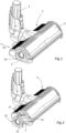
- THE figures 1 to 10 represent a suction head 2 comprising a connection sleeve 3 to which a tip of a rigid or flexible tube is intended to be connected, itself connected to a suction system of a vacuum cleaner (not shown).
- a vacuum cleaner (not shown)
- the suction head 2 comprises a main body 4 configured to be moved on a surface to be cleaned.
- the connecting sleeve 3 is advantageously mounted in a pivot connection relative to the main body 4 so as to allow the connecting sleeve 3 to pivot, relative to the main body 4, forwards and backwards when the suction head 2 moves in a direction of movement D1.
- the main body 4 comprises a sole 5 provided with a lower face 6 configured to be oriented towards the surface to be cleaned, and a suction mouth 7 opening onto the lower face 6.
- the suction mouth 7 communicates with the connecting sleeve 3 in particular by means of a suction duct formed at least in part for example by a flexible connecting duct.
- the suction mouth 7 may for example have an elongated shape and extend transversely, and for example perpendicularly, to the direction of movement D1 of the suction head 2.
- the main body 4 further comprises a suction chamber 9 which opens into the lower face 6 of the sole 5 via the suction mouth 7, and which is fluidically connected to the suction duct.
- the suction head 2 also comprises a rotating brush 11 comprising a brush body 12 which has a generally tubular shape and which has a central longitudinal axis A.
- the brush body 12 is mounted to rotate in the suction chamber 9 around an axis of rotation which is coaxial with the central longitudinal axis A of the brush body 12.
- the brush body 12 is removably mounted in the suction chamber 9 and is configured to be inserted into and removed from the suction chamber 9 in a mounting direction D2.
- the mounting direction D2 extends transversely, and preferably perpendicularly, to the direction of movement D1 of the suction head 2.
- the main body 4 comprises a passage opening 13 opening into the suction chamber 9 and through which the brush body 12 can be inserted into and removed from the suction chamber 9.
- the passage opening 13 is provided on a side wall of the main body 4.
- the rotating brush 11 comprises bristles 14 provided on the external surface of the brush body 12.
- the brush body 12 is generally cylindrical with a circular section, and the rotating brush 11 comprises a plurality of rows of bristles extending for example helically around the central longitudinal axis A of the brush body 12.
- the rows of bristles could be replaced by elastically deformable lamellae or by a foam cleaning sleeve.
- the rotating brush 11 could comprise at least one row of bristles and at least one elastically deformable lamella.
- the suction head 2 further comprises a closing cap 15 which is configured to at least partially close the passage opening 13 when the brush body 12 is mounted in the suction chamber 9.
- the suction head 2 also comprises a drive device 16 configured to drive the brush body 12 in rotation about the axis of rotation.
- the drive device 16 more particularly comprises a drive motor 17, preferably electric, comprising an output shaft 18 which is coaxial with the axis of rotation of the brush body 12.
- the drive motor 17 is housed in a motor compartment 19 fixed to a side wall of the main body 4, and the motor compartment 19 and the drive motor 17 are arranged in a motor housing 21 delimited by the brush body 12.
- the drive motor 17 comprises a motor housing 22, and also a rotor and a stator (not shown in the figures) which are housed in the motor housing 22.
- the drive motor 17 is located at a distance from the side walls of the main body 4.
- the drive motor 17 is off-center with respect to a median vertical plane of the body main body 4 and is arranged between the median vertical plane of the main body 4 and one of the two side walls.
- the brush body 12 comprises a first end portion 12.1 which is located near the drive device 16 and which delimits the motor housing 21, and a second end portion 12.2 which is supported by the closing cap 15 and which is mounted to be movable in rotation relative to the closing cap 15.
- the rotating brush 11 further comprises a coupling portion 24 which is arranged in the brush body 12 and which is configured to rotationally couple with a complementary coupling portion 25 which belongs to the drive device 16 and which is rotationally coupled to the output shaft 18 of the drive motor 17.
- the coupling portion 24 is a female coupling portion and the complementary coupling portion 25 is a male coupling portion.
- the coupling portion 24 could be a male coupling portion and the complementary coupling portion 25 could be a female coupling portion.
- the suction head 2 also comprises a support ring 26 which is fixed to the first end portion 12.1 of the brush body 12 and which is configured to support the first end portion 12.1, and an additional support ring 27 which is fixed, for example by gluing or welding, to the second end portion 12.2 of the brush body 12 and which is configured to support the second end portion 12.2.
- the support ring 26 and the additional support ring 27 are arranged coaxially with the central longitudinal axis A of the brush body 12, and the drive motor 17 is arranged axially between the support ring 26 and the additional support ring 27.
- the drive motor 17 is closer to the support ring 26 than to the additional support ring 27.
- the drive motor 17 is arranged axially between the support ring 26 and the median vertical plane of the brush body 12.
- the suction head 2 further comprises a bearing 28, such as a rolling bearing and for example a ball bearing, configured to guide the support ring 26 in rotation, and an additional bearing 29, such as a rolling bearing and for example a ball bearing, configured to guide the additional support ring 27 in rotation.
- a bearing 28 such as a rolling bearing and for example a ball bearing
- an additional bearing 29 such as a rolling bearing and for example a ball bearing, configured to guide the additional support ring 27 in rotation.
- the additional bearing 29 is interposed between the additional support ring 27 and a support part belonging to the closing cap 15.
- the bearing 28 more particularly comprises an inner ring 28.1 which is fixed to the bearing support 31 and which extends around the bearing support 31, and an outer ring 28.2 which is rotatable relative to the inner ring 28.1 and which is fixed to the support ring 26.
- the support ring 26 is arranged in the first end portion 12.1 of the brush body 12, and is interposed between the outer ring 28.2 of the bearing 28 and an inner circumferential surface of the brush body 12.
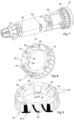
- the support ring 26 comprises an inner wall 32 which is generally cylindrical and which extends around and in contact with the outer ring 28.2 of the bearing 28, and an outer wall 33 which is generally cylindrical and which cooperates with the inner circumferential surface of the brush body 12.
- the suction head 2 advantageously comprises a fixing device configured to fix the bearing 28 to the support ring 26.
- the fixing device comprises a plurality of fixing lugs 34 which are provided on the support ring 26, which are distributed around the central axis of the support ring 26 and which extend substantially parallel to the central axis of the support ring 26.
- the fixing lugs 34 are configured to cooperate with the bearing 28, and more particularly with the outer ring 28.2 of the bearing 28, so as to fix the bearing 28 to the support ring 26 and in particular so as to axially immobilize the bearing 28 relative to the support ring 26.
- the support ring 26 comprises a bearing housing 35 in which the bearing 28 is received, and each fixing lug 34 is elastically deformable and comprises a retaining portion configured to retain the bearing 28 in the bearing housing 35.
- the support ring 26 may for example comprise a plurality of stop members 36, such as stop ribs, distributed around the central axis of the support ring 26 and extending circumferentially.
- Each stop member 36 partly delimits the bearing housing 35 and is provided with an axial stop surface against which the bearing 28 abuts when the bearing 28 is housed in the bearing housing 35.
- the engine compartment 19 is fixed to the bearing support 31, and the bearing 28 is axially sandwiched between a first abutment surface provided on the bearing support 31 and a second abutment surface provided on the engine compartment 19.
- the engine compartment 19 comprises a motor cover 37 extending around the drive motor 17 and a cover support 38 fixed to the bearing support 31 and configured to support the motor cover 37.
- the motor cover 37 more particularly comprises a tubular wall 37.1 which extends around the drive motor 17 and which is substantially coaxial with the motor axis of the drive motor 17, and an end wall 37.2 located opposite the cover support 38 and provided with a central opening through which the output shaft 18 of the drive motor 17 projects.
- the motor cover 37 further comprises an open end which is at least partially closed by the cover support 38.
- the suction head 2 comprises a damping element 39 interposed axially between the drive motor 17 and the hood support 38.
- the suction head 2 further comprises an air circulation cooling circuit 41 which is delimited at least in part by the bearing support 31, the drive motor 17, the motor compartment 19, the brush body 12 and the support ring 26 and which is fluidically connected to the suction chamber 9.
- the suction head 2 is configured such that, when a negative pressure is generated in the suction chamber 9, air is sucked into the air circulation cooling circuit 41 from outside the rotating brush 11 and is circulated in the air circulation cooling circuit 41, in order to ensure cooling in particular of the drive motor 17 and the bearing 28.
- the air circulation cooling circuit 41 comprises at least one air intake opening 42 through which air is capable of being drawn into the air circulation cooling circuit 41.
- the air intake opening(s) 42 is (are) provided on a side wall of the main body 4, and more particularly on the side wall of the brush body to which the bearing support 31 is fixed.
- the air circulation cooling circuit 41 further comprises a plurality of air discharge openings through which air flowing into the air circulation cooling circuit 41 is adapted to be discharged out of the air circulation cooling circuit 41.
- the air discharge openings are formed by through holes 44 provided on the support ring 26 and configured to fluidically connect the motor housing 21 to the suction chamber 9, and thus to the suction duct.
- each through hole 44 is distributed around the central axis of the support ring 26, and each through hole 44 opens respectively into a first axial face 26.1 of the support ring 26 which is oriented towards the drive motor 17 and which partly delimits the motor housing 21 and into a second axial face 26.2 of the support ring 26 which is located outside the brush body 12 and which is oriented towards the side wall of the main body 4 to which the bearing support 31 is fixed.
- Each through hole 44 is more particularly configured to allow the passage of an air flow through said through hole 44 and from the first axial face 26.1 of the support ring 26 (and therefore from the motor housing 21) towards the second axial face 26.2 of the support ring 26 (and therefore towards the outside of the rotating brush 11).
- each through hole 44 provided on the support ring 26 is delimited by the inner and outer walls 32, 33 of the support ring 26 and by two flow guide walls 45 which are inclined relative to the central axis of the support ring 26 and which are located opposite each other.
- the flow guide walls 45 are regularly distributed around the central axis of the support ring 26, and are configured to mechanically connect the inner and outer walls 32, 33 of the support ring 26 to each other.
- each flow guide wall 45 which partly delimit a respective through hole 44, are more particularly configured to generate a vacuum within the respective through hole 44 when the drive motor 17 is running and drives the rotating brush 11 and the support ring 26 in rotation.
- each flow guide wall 45 provided on the support ring 26 forms a flow guide vane
- the support ring 26 forms a turbine provided with flow guide vanes distributed around the central axis of the support ring 26.
- each flow guide vane, and therefore each flow guide wall 45 has an axial dimension and a radial dimension which is smaller than the respective axial dimension.
- the air circulation cooling circuit 41 more particularly comprises a first circuit portion 41.1 which comprises the at least one air intake opening 42 and which is delimited in part by the bearing support 31, the cover support 38, the drive motor 17 and the motor cover 37, and a second circuit portion 41.2 which comprises the air discharge openings (formed by the through holes 44), which is partly delimited by the motor compartment 19 and the brush body 12 and which is located downstream of the first circuit portion.
- the air circulation cooling circuit 41 is configured such that, when a vacuum is generated in the suction chamber 9, the air, circulated in the air circulation cooling circuit 41, flows in the first circuit portion 41.1 away from the support ring 26 (and therefore towards the closing cap 15), and flows in the second circuit portion 41.2 towards the support ring 26.
- the bearing support 31 is hollow and comprises an air flow duct 46 which extends substantially coaxially with the bearing 28 and which partly forms the first circuit portion 41.1.
- the air flow duct 46 is fluidically connected to the at least one air intake opening 42, and the bearing 28 extends around the air flow duct 46.
- the air flow duct 46 is fluidically connected to an internal housing delimited by the engine compartment 19 (and partly forming the first circuit portion 41.1) via at least one passage orifice 31.1 (see Figure 10 ) provided on the bearing support 31 and opening into the air flow duct 46, and at least one air flow passage 38.1 (see the figures 6 And 10 ) provided on the hood support 38 and fluidly connecting the at least one passage orifice 31.1 to the internal housing delimited by the engine compartment 19.
- the air circulation cooling circuit 41 is configured such that, when a vacuum is generated in the suction chamber 9, the air, circulated in the first circuit portion 41.1, flows at least partly inside the drive motor 17.
- the first circuit portion 41.1 comprises at least one air inlet opening 49 provided on a peripheral wall of the motor housing 22 and through which the air, circulated in the air circulation cooling circuit 41 when a vacuum is generated in the suction chamber 9, is able to penetrate into the drive motor 17, and at least one air outlet opening 50 provided on an end wall of the motor housing 22 (which is located opposite the support ring 26) and through which the air, having entered the drive motor 17 via the at least one air inlet opening 49, is able to flow outside the drive motor 17.
- the at least one air inlet opening 49 is oriented substantially radially and opens into the internal housing delimited by the engine compartment 19, and the at least one air outlet opening 50 is oriented substantially axially.
- the motor compartment 19 and the brush body 12 delimit a connecting chamber 52 which is located axially opposite the support ring 26 relative to the drive motor 17 and which is configured to fluidically connect the first circuit portion 41.1 to the second circuit portion 41.2.
- the at least one air outlet opening 50 provided on the motor housing 22, is fluidically connected to the connecting chamber 52 via at least one connecting orifice 51 (see the Figure 10 ) provided on the engine cover 37, and more particularly on the end wall 37.2 of the engine cover 37.
- the air circulation cooling circuit 41 is configured such that, when a vacuum is generated in the suction chamber 9, the air, circulated in the second circuit portion 41.2, flows between an external surface of the motor compartment 19 and an internal surface of the brush body 12, before reaching the through holes 44 provided on the support ring 26.
- the air circulation cooling circuit 41 is configured such that, when a vacuum is generated in the suction chamber 9, the air, circulated in the second circuit portion 41.2, flows substantially parallel to the central longitudinal axis A of the brush body 12.
- Cooling of the bearing 28 and the drive motor 17 via the air circulation cooling circuit 41 is described below.
- the air is then discharged from the drive motor 17 via the at least one air outlet opening 50, enters the connecting chamber 52 via the at least one connecting orifice, flows towards the support ring 26 via the annular longitudinal passage delimited between the motor compartment 19 and the brush body 12, and is discharged from the rotating brush 11 via the through holes 44 and is sucked into the suction duct.
- the air ensures cooling, by thermal conduction, of the support ring 26 and the outer ring 28.2 of the bearing 28.
- the inner wall 32 of the support ring 26 comprises a plurality of radial through-openings 54 distributed around the central axis of the support ring 26.
- Each radial through-opening 54 extends in a radial direction and opens into a respective through-hole 44 provided on the support ring 26, and is located opposite the bearing 28, and more particularly opposite the outer ring 28.2 of the bearing 28.
- Such a configuration of the support ring 26 makes it possible to further promote the cooling of the bearing 28 by the air flows flowing through the through-holes 44.
Landscapes
- Engineering & Computer Science (AREA)
- Mechanical Engineering (AREA)
- Nozzles For Electric Vacuum Cleaners (AREA)
Applications Claiming Priority (1)
| Application Number | Priority Date | Filing Date | Title |
|---|---|---|---|
| FR2309351A FR3152368B1 (fr) | 2023-09-06 | 2023-09-06 | Tête d’aspiration pourvue d’une bague de support ajourée |
Publications (1)
| Publication Number | Publication Date |
|---|---|
| EP4520237A1 true EP4520237A1 (de) | 2025-03-12 |
Family
ID=88839044
Family Applications (1)
| Application Number | Title | Priority Date | Filing Date |
|---|---|---|---|
| EP24198255.2A Pending EP4520237A1 (de) | 2023-09-06 | 2024-09-03 | Saugkopf mit durchbrochenem stützring |
Country Status (6)
| Country | Link |
|---|---|
| US (1) | US20250072680A1 (de) |
| EP (1) | EP4520237A1 (de) |
| JP (1) | JP2025043301A (de) |
| KR (1) | KR20250036020A (de) |
| CN (1) | CN120240884A (de) |
| FR (1) | FR3152368B1 (de) |
Families Citing this family (1)
| Publication number | Priority date | Publication date | Assignee | Title |
|---|---|---|---|---|
| USD1094935S1 (en) * | 2024-01-02 | 2025-09-23 | Calor | Vacuum cleaner suction head |
Citations (2)
| Publication number | Priority date | Publication date | Assignee | Title |
|---|---|---|---|---|
| EP2811884A1 (de) * | 2012-02-08 | 2014-12-17 | Dyson Technology Limited | Reinigungskopf für einen staubsauger |
| EP3900595A1 (de) * | 2020-04-23 | 2021-10-27 | Seb S.A. | Reinigungseinheit für saugkopf |
-
2023
- 2023-09-06 FR FR2309351A patent/FR3152368B1/fr active Active
-
2024
- 2024-09-02 KR KR1020240118314A patent/KR20250036020A/ko active Pending
- 2024-09-03 EP EP24198255.2A patent/EP4520237A1/de active Pending
- 2024-09-03 CN CN202411225485.4A patent/CN120240884A/zh active Pending
- 2024-09-06 US US18/826,657 patent/US20250072680A1/en active Pending
- 2024-09-06 JP JP2024153819A patent/JP2025043301A/ja active Pending
Patent Citations (2)
| Publication number | Priority date | Publication date | Assignee | Title |
|---|---|---|---|---|
| EP2811884A1 (de) * | 2012-02-08 | 2014-12-17 | Dyson Technology Limited | Reinigungskopf für einen staubsauger |
| EP3900595A1 (de) * | 2020-04-23 | 2021-10-27 | Seb S.A. | Reinigungseinheit für saugkopf |
Also Published As
| Publication number | Publication date |
|---|---|
| US20250072680A1 (en) | 2025-03-06 |
| CN120240884A (zh) | 2025-07-04 |
| JP2025043301A (ja) | 2025-03-28 |
| FR3152368B1 (fr) | 2025-08-01 |
| KR20250036020A (ko) | 2025-03-13 |
| FR3152368A1 (fr) | 2025-03-07 |
Similar Documents
| Publication | Publication Date | Title |
|---|---|---|
| EP1404203B1 (de) | Selbständiger hochwirksamer staubsauger | |
| EP3603473B1 (de) | Reinigungskopf, der mit einer rotierenden bürste ausgestattet ist | |
| EP3900597B1 (de) | Drehbürste für saugkopf | |
| EP3900595B1 (de) | Reinigungseinheit für saugkopf | |
| EP4523589A1 (de) | Saugkopf mit einem kühlkreislauf für den bürstenmotor | |
| FR3152368A1 (fr) | Tête d’aspiration pourvue d’une bague de support ajourée | |
| EP3662803B1 (de) | Hausstaubsauger, der mit einem schallabsorptionselement ausgestattet ist | |
| EP3626146B1 (de) | Ansaugvorrichtung für haushaltssauger | |
| EP3626148B1 (de) | Ansaugvorrichtung für haushaltssauger | |
| EP3626147B1 (de) | Ansaugvorrichtung für haushaltssauger | |
| WO2021058908A1 (fr) | Dispositif de refroidissement par jets d'air d'un carter de turbine | |
| EP3626143B1 (de) | Ansaugvorrichtung für haushaltssauger | |
| EP3698694B1 (de) | Staubsauger, der mit einem verbindungschlauch ausgestattet ist | |
| EP4311467B1 (de) | Saugkopf mit rückseitiger dichtungslamelle | |
| EP4385376B1 (de) | Absaugvorrichtung für haushaltsstaubsauger | |
| EP4304431B1 (de) | Motorisierte basis für ein gerät zur zubereitung von lebensmitteln mit geräuscharmer entlüftung | |
| EP3698695B1 (de) | Besenstaubsauger, der mit einem hauptkorpus ausgestattet ist, der aus einer ersten und einer zweiten halbschale gebildet ist | |
| FR2992683A1 (fr) | Dispositif d'attenuation du bruit genere par un ventilateur d'automobile | |
| EP4311466A1 (de) | Saugkopf mit einer drehbürste mit reinigungslamelle | |
| EP4388959A1 (de) | Autonomer reinigungsroboter mit abfalldeflektoren | |
| WO2024134065A1 (fr) | Robot de nettoyage autonome équipé de déflecteurs de déchets |
Legal Events
| Date | Code | Title | Description |
|---|---|---|---|
| PUAI | Public reference made under article 153(3) epc to a published international application that has entered the european phase |
Free format text: ORIGINAL CODE: 0009012 |
|
| STAA | Information on the status of an ep patent application or granted ep patent |
Free format text: STATUS: THE APPLICATION HAS BEEN PUBLISHED |
|
| AK | Designated contracting states |
Kind code of ref document: A1 Designated state(s): AL AT BE BG CH CY CZ DE DK EE ES FI FR GB GR HR HU IE IS IT LI LT LU LV MC ME MK MT NL NO PL PT RO RS SE SI SK SM TR |
|
| STAA | Information on the status of an ep patent application or granted ep patent |
Free format text: STATUS: REQUEST FOR EXAMINATION WAS MADE |
|
| 17P | Request for examination filed |
Effective date: 20250828 |
|
| GRAP | Despatch of communication of intention to grant a patent |
Free format text: ORIGINAL CODE: EPIDOSNIGR1 |
|
| STAA | Information on the status of an ep patent application or granted ep patent |
Free format text: STATUS: GRANT OF PATENT IS INTENDED |
|
| INTG | Intention to grant announced |
Effective date: 20260102 |
|
| GRAS | Grant fee paid |
Free format text: ORIGINAL CODE: EPIDOSNIGR3 |
|
| GRAA | (expected) grant |
Free format text: ORIGINAL CODE: 0009210 |
|
| STAA | Information on the status of an ep patent application or granted ep patent |
Free format text: STATUS: THE PATENT HAS BEEN GRANTED |