EP4520435A1 - Rotor de broyage pour broyeur de minerai - Google Patents
Rotor de broyage pour broyeur de minerai Download PDFInfo
- Publication number
- EP4520435A1 EP4520435A1 EP23196589.8A EP23196589A EP4520435A1 EP 4520435 A1 EP4520435 A1 EP 4520435A1 EP 23196589 A EP23196589 A EP 23196589A EP 4520435 A1 EP4520435 A1 EP 4520435A1
- Authority
- EP
- European Patent Office
- Prior art keywords
- grinding
- protective elements
- mill
- grinding rotor
- coating
- Prior art date
- Legal status (The legal status is an assumption and is not a legal conclusion. Google has not performed a legal analysis and makes no representation as to the accuracy of the status listed.)
- Pending
Links
Images



Classifications
-
- B—PERFORMING OPERATIONS; TRANSPORTING
- B02—CRUSHING, PULVERISING, OR DISINTEGRATING; PREPARATORY TREATMENT OF GRAIN FOR MILLING
- B02C—CRUSHING, PULVERISING, OR DISINTEGRATING IN GENERAL; MILLING GRAIN
- B02C17/00—Disintegrating by tumbling mills, i.e. mills having a container charged with the material to be disintegrated with or without special disintegrating members such as pebbles or balls
- B02C17/16—Mills in which a fixed container houses stirring means tumbling the charge
-
- B—PERFORMING OPERATIONS; TRANSPORTING
- B02—CRUSHING, PULVERISING, OR DISINTEGRATING; PREPARATORY TREATMENT OF GRAIN FOR MILLING
- B02C—CRUSHING, PULVERISING, OR DISINTEGRATING IN GENERAL; MILLING GRAIN
- B02C17/00—Disintegrating by tumbling mills, i.e. mills having a container charged with the material to be disintegrated with or without special disintegrating members such as pebbles or balls
- B02C17/16—Mills in which a fixed container houses stirring means tumbling the charge
- B02C17/163—Stirring means
-
- B—PERFORMING OPERATIONS; TRANSPORTING
- B02—CRUSHING, PULVERISING, OR DISINTEGRATING; PREPARATORY TREATMENT OF GRAIN FOR MILLING
- B02C—CRUSHING, PULVERISING, OR DISINTEGRATING IN GENERAL; MILLING GRAIN
- B02C17/00—Disintegrating by tumbling mills, i.e. mills having a container charged with the material to be disintegrated with or without special disintegrating members such as pebbles or balls
- B02C17/18—Details
- B02C17/22—Lining for containers
-
- B—PERFORMING OPERATIONS; TRANSPORTING
- B02—CRUSHING, PULVERISING, OR DISINTEGRATING; PREPARATORY TREATMENT OF GRAIN FOR MILLING
- B02C—CRUSHING, PULVERISING, OR DISINTEGRATING IN GENERAL; MILLING GRAIN
- B02C2210/00—Codes relating to different types of disintegrating devices
- B02C2210/01—Indication of wear on beaters, knives, rollers, anvils, linings and the like
Definitions
- the invention relates to a grinding rotor for an ore mill having a body configured as a disc. Further, the invention also relates to a method for manufacturing a grinding rotor, to an ore mill comprising at least one grinding rotor as well as to a method of grinding particulate ore mineral material.
- Grinding rotors for ore mills are used to stir particulate mineral ore material and grinding media within a mill body in order to obtain ground mineral particles.
- a plurality of grinding rotors are usually arranged on a shaft located within the mill body and rotated about an axis by said shaft. Thereby, the rotation of the grinding rotors induces a circular flow of the particulate mineral ore material and grinding media within the mill body. This leads to attrition between the grinding media and the particulate mineral ore material which brakes up the latter into smaller mineral particles.
- direct contact of the grinding material on the grinding rotors produces a high wear on the grinding rotors, which may lead to severe damages thereto necessitating a replacement of the grinding rotor.
- grinding rotors having protective elements have been developed.
- EP 4 132 713 describes a grinding rotor comprising a planar body having an axis of rotation around which the body is configured to rotate during use as well as a plurality of protective elements provided on the body and extending transversely across the body.
- the protective elements are spaced apart from each other around the axis of rotation, at least some of the protective elements have a rotationally leading face that is angled relative to an orthogonal line extending orthogonally from the axis of rotation of the body.
- the protective elements are provided on the body, extend laterally outwardly from either one or both of the surfaces of the body, and extend beyond the outer edge of the body.
- Said grinding rotor comprises one or more protective elements to deflect particulate material and grinding media from the planar body.
- the protective elements extend radially from an outer edge of the body as well as from opposed surfaces of the body.
- grinding rotors with protective elements still suffer some drawbacks, as explained in the following:
- the grinding media usually in the form of ceramic balls, is filled within the mill body only to a certain height, leaving a free space above the grinding media filled space of the mill body.
- the particulate mineral ore material usually raises through this free space after having been inserted into the mill body through an inlet opening, which is usually located on the bottom of the mill body.
- grinding rotors with no protective elements may be used, as no collision with grinding media is to be expected.
- the height of the grinding media filled space of the mill body usually increases.
- the grinding rotor for an ore mill comprises a body configured as a disc with two opposed surfaces and a circumference.
- the body is rotatable about a central axis and comprises a plurality of protective elements evenly spaced apart of each other on at least one of the two surfaces of the body and protruding from the at least one surface.
- the body as well as the plurality of protective elements are made of a first material or first composition.
- a first coating completely encases the body and at least completely fills spaces between the protective elements, thereby forming a disc shaped shell on the body, the first coating being made of a second material or second composition which has a lower wear resistance than the first material or the first composition.
- Provision of the first coating leads to a grinding rotor having a substantially smooth surface which may be used outside of the space filled with grinding material without the risk of damages to a mill housing.
- the interaction of the grinding material with the grinding rotor will wear off the first coating over time, hence exposing the body with the plurality of protective elements. Therefore, grinding rotors will have an outer shape which adapts over time depending on the exposure of the grinding rotor to the grinding material.
- the grinding rotor will therefore always exhibit an outer surface that is optimally adapted to the fill level of grinding material within a mill body in which the grinding rotor is used, i.e. with exposed protection elements in a space filled with grinding material and with a smooth outer surface in a space above the grinding material.
- the grinding rotor according to the present invention allows for an optimal grinding process with a reduced occurrence of damages to an inner wall of the mill body and with a reduced wear of the grinding rotors.
- the grinding rotor has the shape of a disc with a defined radius and with a defined height in a direction orthogonal to the radius.
- the radius thereby is larger than the height, preferably at least double the height.
- the circumference defines a circumferential edge surface of the body.
- the body comprises a rotation centre which is concurrent with the origin of the disc.
- the central axis intersects with the rotation centre and is orthogonal to the radius of the disc.
- the central axis thereby is parallel to the height of the disc.
- the disc preferably comprises an aperture in the area of the rotation centre through which a shaft of the ore mill may be inserted.
- the aperture preferably is circular and concentric with the rotation centre of the disc.
- the aperture may be of any suitable shape, such as rectangular, hexagonal or any other polygonal shape.
- the body preferably comprises connection means, preferably located next to or close by the aperture in order to releasably connect the body a the shaft of the mill.
- the plurality of protective elements preferably are distributed at even angular distances from each other on the at least one of the two opposed surfaces of the body.
- the plurality of protective elements are spaced from each other at an angular distance of 360°/n, where n is the number of protective elements on the at least one surface.
- the protective elements protrude from the at least one surface and away thereof in a direction substantially parallel to the central axis.
- the protective elements preferably extend from the rotation centre of the body or from an edge of an aperture located in the area of the rotation centre at least to the circumference of the body. Thereby, the protective elements may follow a straight line from the rotation centre at least to the circumference or they may follow a curved or meandering line. If the protective elements are following a meandering line, the meandering line preferably is in the shape of a sinusoid. In order to avoid any unbalance of the body when the body is rotated about the central axis, the plurality of protective elements are shaped and distributed about the at least one surface such that the centre of mass of the grinding rotor is located on the central axis.
- each of the protective elements may be configured as a single block of any suitable shape extending from the rotation centre at least to the circumference of the body and following an imaginary line on said body.
- each protective element may be configured as a series of protrusions following a straight, curved or meandering imaginary line from the rotation centre at least to the circumference of the body.
- the imaginary line is in the shape of a meandering line
- the meandering line preferably has a sinusoid shape.
- the protrusions may be of any suitable shape, e.g. cubes, hemispheres, pyramids, rods or the like.
- the protective elements are preferably arranged on a radius of the body, i.e. the protective elements follow an imaginary line which is congruent with a radius of the body.
- a middle axis of the cuboid is thereby preferably parallel to a radius in the direction of the central axis.
- a bisecting axis of the imaginary meandering line preferably is congruent with a radius of the body.
- the curvature of the imaginary line preferably starts at the rotation centre or an edge of an aperture located in the area of the rotation centre and follows a curvature up to at least the circumference of the body.
- the imaginary line is arranged at an angle relative to a tangent of the circumference when reaching the circumference.
- the curved imaginary line preferably has a constant radius, i.e. corresponds to a circular arc.
- the curved imaginary line may be in the form of a partial ellipse, of a hyperbole or any other suitable curved shape.
- the protective elements may be inclined at a defined angle relative to a radius of the body. This means that a middle axis of cuboid shaped protective elements intersects a radius of the body at the defined angle.
- a bisecting axis of the meandering imaginary line intersects a radius of the body at the defined angle. The middle axis or bisecting axis may thereby intersect the radius at any location along the radius.
- the protective elements are configured as discs protruding from the at least one surface in a direction parallel to the central axis, each of said discs preferably having a diameter which spans at least from the circumference to an aperture located in the area of the rotation centre, i.e. the diameter of each disc corresponds to the distance along a radius of the body from the circumference of the body to an edge of the aperture, wherein the origin of each disc shaped protective element is arranged on a radius of the body.
- all protective elements of the grinding rotor have the same shape and same dimensions.
- the protective elements may be of two or more different shapes and/or dimensions.
- all protective elements have the same extension in a direction parallel to the central axis, i.e. all protective elements have the same height relative to the at least one surface.
- the protective elements have a substantially flat top surface which is preferably parallel to the at least one surface of the body. The top surface of the protective elements is the surface which is spaced from the at least one surface of the body.
- the body and the protective elements are made of the same first material.
- the body and the protective elements are made as a single piece.
- such a single piece may be manufactured by die casting, compression moulding, injection moulding, milling or any other suitable fabrication method.
- the body as well as each of the plurality of protective elements are individual pieces, wherein the protective elements are subsequently fastened to the body, e.g. by welding, gluing or by means of mechanical fasteners, such as screws, bolts, rivets or the like.
- the first coating encases the body, i.e. the first coating completely envelops the body of the grinding rotor. This means that the first coating is applied on both surfaces of the body as well as around the circumference thereof. Further, the first coating completely fills spaces between the protective elements, i.e. any space between two adjacent protective elements is completely filled with the first coating. The first coating thereby reaches at least to the level of the top surface of the protective elements in the direction of the central axis. In this way, the first coating forms a shell around the body.
- the shell preferably has substantially smooth surfaces, which are further preferably parallel to the two surfaces and to the circumferential edge surface of the body.
- the second material or second composition of the first coating has a lower wear resistance than the first material or first composition and will hence wear off more quickly during use of the grinding rotor in an ore mill.
- the second material or second composition has a wear resistance which is at least 20%, more preferably at least 30%, even more preferably 40% and most preferably at least 50% lower than the wear resistance of the first material or first composition.
- the first material has a volume loss of between 30 mm 3 to 60 mm 3 , as measured according to the standard ISO 4649:2017, Method A.
- the second material has a volume loss of between 65 mm 3 to 160 mm 3 , as measured according to the standard ISO 4649:2017, Method A.
- a higher volume loss indicates a lower wear resistance as compared to a smaller volume loss. I.e. the smaller the volume loss the better the wear resistance of the material.
- the first material has a shore A hardness of between 60 to 90.
- a shore A hardness of between 60 to 90.
- the use of a first material having a shore A hardness in this range yields the best results, as the first material is able to withstand deformation by impacts with grinding media while still being able to slightly yield upon such impacts, so that the grinding elements are not catapulted with too high energy away of the grinding rotor.
- the first material has a tensile strength of between 16 MPa to 30 MPa as measured according to the standard ISO 37:2017.
- the first material has an elongation at break of between 480% to 650% as measured according to the standard ISO 37:2017.
- the second material preferably has a tensile strength of between 25 MPa and 35 MPa as measured according to the standard ISO 37:1997.
- the second material has an elongation at break of between 400% and 600% as measured according to the standard ISO 37:2017.
- the first and the second material is a mixture of natural rubber (NR) and butadiene rubber (BR) most preferably having a volume loss and tensile strength as specified above.
- the first material may comprise a natural rubber (NR) or a mixture of natural rubber (NR) and butadiene rubber (BR) while the second material comprises a polyurethane, preferably a polyurethane based on a polyether polyol or polyester polyol.
- the first material may comprise a polyurethane while the second material may comprise a natural rubber (NR) or a mixture of natural rubber (NR) and butadiene rubber (BR).
- the body comprises protective elements on both surfaces.
- the protective elements have the same configuration on both surfaces, especially in view of the shape, dimensions and/or the spacing of the protective elements.
- the configuration of both sides of the body, especially in view of the configuration of the protective elements is symmetric in view of a tangent plane of the central axis cutting the body in the middle of its height.
- At least one of the plurality of protection elements protrude outward of the circumference of the body.
- the at least one protection element extend further from the rotation centre than the circumference of the body.
- the at least one protection element comprises a part which forms an overhang protruding from the circumference of the body.
- all protective elements protrude outward of the circumference of the body.
- only a fraction of the protective elements protrude outward of the circumference of the body, such as e.g. half of the protective elements.
- the at least one protective element is additionally configured to protrude from the circumferential edge surface of the body. This means that the part of the at least one protective element that overhangs from the circumference extends at least partially over the circumferential edge surface of the body.
- the body comprises protective elements on both surfaces
- protective elements arranged symmetrically to each other on both surfaces preferably are connected by means of the part extending at least partially over the circumferential edge surface of the body.
- the protective elements as well as the part form a kind of C-shaped element when viewed in a direction orthogonal to the central axis.
- the plurality of protective elements are all completely encased by the first coating.
- the first coating extends over each surface of the protective elements.
- the first coating thereby forms a shell in the shape of a disc completely encasing the grinding rotor.
- the casing comprises an aperture which is congruent with an aperture of the disc, such that the grinding rotor may be arranged on a shaft of the ore mill.
- the body comprises a core made of a metal or metal alloy, preferably steel, completely encased in the first material.
- This configuration provides more dimensional stability to the body.
- the first material thereby forms a kind of second coating around the core.
- the core is preferably also in the shape of a disc, albeit with smaller dimensions, i.e. a smaller radius and a smaller height as the dimensions of the body.
- the first material or composition comprises at least one polyurethane, at least one natural rubber (NR), at least one butadiene rubber (BR), or a mixture thereof.
- the first material comprises a mixture of at least one natural rubber (NR) and at least one butadiene rubber (BR).
- the second material or composition comprises at least one polyurethane, at least one natural rubber (NR), at least one butadiene rubber (BR), or a mixture thereof.
- NR natural rubber
- BR butadiene rubber
- the body comprises an annular recess separating the disc into an outer annular element and an inner annular element. Both annular elements are concentric and are connected to each other by means of at least two bridges.
- the plurality of protective elements are arranged on at least one surface of the outer annular element and the first coating at least partially encases the outer annular element.
- the present application further relates to a method for manufacturing a grinding rotor for an ore mill.
- a body of the grinding rotor is manufactured.
- the body is configured as a disc with two opposed surfaces and a circumference.
- the body is rotatable about a central axis and comprises a plurality of protective elements evenly spaced apart of each other on at least one of the two surfaces of the body and protruding from the at least one surface.
- the body as well as the plurality of protective elements are made of a first material or first composition.
- a first coating is applied on the body an in spaces between the protective elements such that the body is completely encased by and the spaces are at least completely filled with the first coating, the coating being made of a second material or second composition which has a lower wear resistance than the first material.
- the second material or second composition is cured or vulcanized.
- the grinding rotor manufactured by the method preferably is a grinding rotor according to an embodiment as disclosed above.
- the second material or composition is applied to the body in a flowable state in any suitable means, e.g. by spraying or casting on the body and into the spaces.
- any suitable means e.g. by spraying or casting on the body and into the spaces.
- the application of the second material or composition is performed in a mould into which the body may be placed.
- the curing or vulcanization of the second material or composition may be performed by any suitable means, e.g. such as by heating, irradiation with light of a specific wavelength, by application of a cross-linking or vulcanization agent, such as e.g. sulphur, peroxides, metallic oxides, acetoxysilane or urethane, by compression moulding, or the like.
- a cross-linking or vulcanization agent such as e.g. sulphur, peroxides, metallic oxides, acetoxysilane or urethane, by compression moulding, or the like.
- the body may be manufactured by any suitable method, such as e.g. by die casting, injection moulding, compression moulding, or milling.
- the present application further relates to an ore grinding mill comprising a mill body and a motor.
- the mill body comprises a drive shaft coupled to the motor and arranged within the mill body.
- a plurality of grinding rotors according to any embodiment as disclosed above are fastened to the drive shaft spaced one from another along a length of the drive shaft.
- the ore grinding mill preferably is a vertical ore grinding mill.
- the ore grinding mill may also be a horizontal ore grinding mill.
- the drive shaft is preferably coupled to the motor by means of a suitable gear, for example by a spur gear, preferably with a plurality of gear wheels.
- the rotational speed of the motor may be reduced by means of the gear, while the torque acting on the drive shaft may be increased.
- the motor preferably is an electric motor.
- the mill body preferably is configured as a cylindrical body and preferably comprises an inlet for introducing grinding media as well as particulate ore material into the mill body, as well as an outlet for retrieving ground mineral particles.
- the inlet preferably is located on the bottom of the mill body and the outlet on the top thereof.
- a length axis of the mill body is preferably arranged vertically relative to a surface on which the ore mill is placed. In the case of a horizontal mill, the length axis is preferably arranged in a horizontal direction, most preferably parallel to a surface on which the ore mill is placed.
- the mill body preferably comprises a plurality of shelves arranged on an inner surface of the mill body. Such shelves Increase the grinding efficiency, as they generate additional grinding zones, thus increasing the grinding force exerted on the mineral ore particles. Further, shelves also prevent mineral ore particles to bypass a grinding rotor.
- the present application further relates to a method for grinding particulate ore material in an ore grinding mill, preferably an ore grinding mill as described further above.
- grinding media is introduces into a mill body of the ore grinding mill such that the mill body is at least partially filled with the grinding media.
- the particulate ore material is introduced into the mill body.
- a drive shaft arranged within the mill body is operated by means of a motor.
- the drive shaft comprises a plurality of grinding rotors according to any embodiment as described above.
- the first coating of the grinding rotors is ablated over time by interaction with the grinding media and the particulate ore material, thereby forming an outer geometry of each grinding rotor which corresponds to a fluidic optimal shape for the positon of the specific grinding rotor along the shaft.
- the operation of the drive shaft i.e. the rotation thereof about its length axis induces a circular motion of the grinding material and the particulate ore material located within the mill body. This circular motion leads to attrition between the grinding material and the particulate ore material which leads to the grinding of the later into smaller mineral particles.
- the grinding material preferably is in the form of ceramic balls.
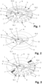
- Figures 1 to 3 show a first embodiment of a grinding rotor 1 for a grinding mill according to the present invention.
- Fig. 1 is a perspective view of the grinding rotor 1 without the first coating 13
- Fig. 2 is a perspective view of the grinding rotor 1 with the first coating 13
- Fig. 3 is a perspective view of the grinding rotor 1 with a partial cut through the first coating 13.
- the grinding rotor 1 comprises a body 2 which is configured as a disc.
- the body 2 comprises a first surface 3 and a second surface 4, which lies opposite to the first surface 3 and is parallel thereto. Further, the body 2 comprises a circumference 5.
- the body 2 comprises an annular recess 7 which divides the body 2 into an outer annular element 8 and an inner annular element 9.
- the outer annular element 8 and the inner annular element 9 are connected to each other by means of three bridges 10.1, 10.2, 10.3 which span across the annular recess 7 in a radial direction.
- the body 2 includes a rotation centre C around which the grinding rotor 1 may be rotated about a central axis A which includes the rotation centre C and is perpendicular to the surfaces 3, 4 of the body 2.
- an aperture 11 is provided on the inner annular element 9 so that the grinding rotor 1 may be connected to a shaft of a grinding mill.
- connection means 12 which are configured as form-fit elements in the embodiment shown are provided on the aperture 11.
- the grinding rotor 1 further comprises a plurality of protective elements 6 which protrude from the first surface 3 as well as the second surface 4 in the embodiment shown. Further, in this embodiment, the protective elements 6 further protrude from the circumference 5 of the body 2 and are all arranged on the outer annular element 8. In this embodiment, the protective elements 6 are generally cubic and each extends along a radius R of the body 2. The protective elements are distributed evenly along the entire circumference of the outer annular element 8.
- the body 2 as well as its protective elements 6 are made of the same first material.
- Fig. 2 shows a perspective view of the same grinding rotor 1 as shown in Fig. 1 , albeit with the first coating 13 applied thereon.
- the first coating 13 is made of a second material which has a lower wear resistance than the first material.
- the coating 13 is applied on the entire outer section 8 in the embodiment shown and completely covers said second section 8 as well as the protective elements 6.
- Fig. 3 which shows the grinding rotor of Fig. 2 with a part of the first coating 13 cut away.
- the thickness of the first coating is chosen such that it is larger than the height of the protective elements 6 in order to completely cover the later.
- the space between each protective element 6 is completely filled with the second material of the first coating 13.
- the first coating 13 also completely covers the parts of the protective elements 6 protruding from the circumference 5 of the disc.
- the first coating 13 provides a ring like shell around the outer annular element 8 of the grinding rotor 1.
- Figures 4 to 6 show a second embodiment of a grinding rotor 1 for a grinding mill according to the present invention.
- Fig. 4 is a perspective view of the grinding rotor 1 of the second embodiment without the first coating 13
- Fig. 5 is a perspective view of the grinding rotor 1 of the second embodiment with the first coating 13
- Fig. 6 is a perspective view of the grinding rotor 1 with a partial cut through the first coating 13.
- the grinding rotor 1 according to this embodiment comprises the same features as the first embodiment shown in Fig. 1 to 3 . However, certain features are configured differently.
- a first apparent difference is that the outer annular element 8 is offset in the direction of the central axis A from the inner annular element 9. Further, instead of using three bridges 10.1, 10.2, 10.3 the embodiment shown only employs two bridges 10.1, 10.2 (of which the second bridge 10.2 is hidden by the outer annular element 8 in the perspective view used). As the outer annular element 8 is offset from the inner annular element 9, the bridges 10.1, 10.2 are angled relative to the annular elements 8, 9.
- the protective elements 6 have a wedge shape when seen in the direction of the first surface 3 or the second surface 4, each of said wedges comprising an angle relative to a radius R of the body 2.
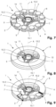
- Figures 7 to 9 show a third embodiment of a grinding rotor 1 for a grinding mill according to the present invention.
- Fig. 7 is a perspective view of the grinding rotor 1 according to the third embodiment without the first coating 13
- Fig. 8 is a perspective view of the grinding rotor 1 of the third embodiment with the first coating 13
- Fig. 9 is a perspective view of the grinding rotor 1 of the third embodiment with a partial cut through the first coating 13.
- the grinding rotor 1 according to the third embodiment comprises the same features as the first embodiment shown in Fig. 1 to 3 and the second embodiment as shown in Fig. 4 to 6 . However, certain features are configured differently.
- the protective elements 6 are configured as discs disposed on the first surface 3 and the second surface 4 in the area of the outer annular element 8.
- the disc shaped protective elements 6 span the entire with of the outer annular element 8 in a direction of a radius R of the body 2. This means that a diameter of each protective element 6 corresponds to the width of the outer annular element 8 in the direction of a radius R of the disc 2. Further, a diameter of each disc shaped protective element 6 is congruent with a radius R of the body 2. Contrary to the first and second embodiment, the protective elements 6 do not protrude from the circumference 5 of the body 2. Another difference is that a bridge protective element 14 is arranged on each of the bridges 10.1, 10.2, 10.3 on both surfaces 3, 4.
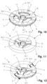
- Figures 10 to 12 show a fourth embodiment of a grinding rotor 1 for a grinding mill according to the present invention.
- Fig. 10 is a perspective view of the grinding rotor 1 according to the fourth embodiment without the first coating
- Fig. 11 is a perspective view of the grinding rotor 1 of the fourth embodiment with the first coating
- Fig. 12 is a perspective view of the grinding rotor 1 of the fourth embodiment with a partial cut through the first coating 13.
- the grinding rotor 1 according to the fourth embodiment is configured similar to the third embodiment as shown in Fig. 7 - 9 with the difference that the protective elements 6 are dome shaped, i.e. the protective elements 6 have the shape of a half sphere.
- Figures 13 to 15 show a fifth embodiment of a grinding rotor 1 for a grinding mill according to the present invention.
- Fig. 13 is a perspective view of the grinding rotor 1 according to the fifth embodiment without the first coating
- Fig. 11 is a perspective view of the grinding rotor 1 of the fifth embodiment with the first coating
- Fig. 12 is a perspective view of the grinding rotor 1 of the fifth embodiment with a partial cut through the first coating 13.
- the grinding rotor 1 comprises the same features as the first embodiment as shown in Fig. 1 to 3 .
- the only difference to the first embodiment is the shape of the protective elements 6.
- the protective elements 6 have the shape of an ellipse when viewed in the direction of one of the surfaces 3, 4. Further, the protective elements 6 do not protrude from the circumference 5 of the body 2.
- Figures 16 to 18 show a sixth embodiment of a grinding rotor 1 for a grinding mill according to the present invention.
- Fig. 16 is a perspective view of the grinding rotor 1 according to the sixth embodiment without the first coating
- Fig. 17 is a perspective view of the grinding rotor 1 of the sixth embodiment with the first coating
- Fig. 18 is a perspective view of the grinding rotor 1 of the sixth embodiment with a partial cut through the first coating 13.
- the grinding rotor 1 comprises the same features as the first embodiment as shown in Fig. 1 to 3 .
- the only difference to the first embodiment is the shape of the protective elements 6.
- the protective elements 6 have the shape of half cylinder protruding from each surface 3, 4. Further, the protective elements 6 do not protrude from the circumference 5 of the body 2.
- Fig. 19 is a schematic side view of a body of a further embodiment of a grinding rotor 1 according to the present invention.
- the body 2 according to this embodiment comprises a core 15 made of a metal or metal alloy which is completely encased by the first material 16. It is to be noted that the protective elements 6 in this embodiment are also made of the first material 16.
- Fig. 20 is a schematic side view of an embodiment of an ore grinding mill 17 according to the present invention.
- the ore grinding mill 17 comprises a mill body 18 which is in the form of a vertical cylinder.
- the ore grinding mill 17 further includes a motor 19 which drives a drive shaft 20 at least partially arranged within the mill body 18.
- a plurality of grinding rotors 1.1, 1.2, 1.3, 1.4, 1.5, 1.6 according to any embodiment described herein are arranged on the drive shaft 20 to be driven in rotation by the motor 19.
- the mill body 18 is at least partially filled with grinding media, such that a spaced filled with grinding media 21 and a space above the grinding media 22 is formed in the mill body 18.
- the particulate ore material When grinding particulate ore material, the particulate ore material is introduced into the mill body 17 through an inlet 24 located in a bottom area of the mill body 18. The particulate ore material will subsequently raise through the space filled with grinding media 21 into the space above the grinding media 22. By rotating the grinding rotors 1.1, 1.2, 1.3, 1.4, 1.5, 1.6 a circular flow of the grinding media and particulate ore material is induced within the space filled with grinding media 21. The particulate ore material is thereby reduced in size by attrition with the grinding media, which is typically provided in the form of ceramic balls. Ground ore material is subsequently removed from the mill body 18 through an outlet 23 located in a top area of the mill body 17.
- the first coating 13 of the grinding rotors 1.1, 1.2, 1.3, 1.4, 1.5, 1.6 is ablated through collisions with the grinding media as well as the particulate mineral material. Thereby, over time, the outer shape of the grinding rotors 1.1, 1.2, 1.3, 1.4, 1.5, 1.6 is ablated to an optimal shape for its relative position within the space filled with grinding media 21, whereby the protective elements may be exposed at least partially or entirely. It is to be noted that the grinding rotors 1.1, 1.2 located in the space above the grinding media 22 will not be subjected to ablation of their first coating and will therefore retain a casing with a smooth surface.
Landscapes
- Engineering & Computer Science (AREA)
- Food Science & Technology (AREA)
- Crushing And Grinding (AREA)
- Polishing Bodies And Polishing Tools (AREA)
- Crushing And Pulverization Processes (AREA)
Priority Applications (5)
| Application Number | Priority Date | Filing Date | Title |
|---|---|---|---|
| EP23196589.8A EP4520435A1 (fr) | 2023-09-11 | 2023-09-11 | Rotor de broyage pour broyeur de minerai |
| CN202480058138.9A CN121816232A (zh) | 2023-09-11 | 2024-08-16 | 用于矿石磨机的研磨转子 |
| AU2024342618A AU2024342618A1 (en) | 2023-09-11 | 2024-08-16 | Grinding rotor for an ore mill |
| PCT/EP2024/073123 WO2025056276A1 (fr) | 2023-09-11 | 2024-08-16 | Rotor de broyage pour un broyeur de minerai |
| MX2026002757A MX2026002757A (es) | 2023-09-11 | 2026-03-06 | Rotor de trituradora para un molino de mena |
Applications Claiming Priority (1)
| Application Number | Priority Date | Filing Date | Title |
|---|---|---|---|
| EP23196589.8A EP4520435A1 (fr) | 2023-09-11 | 2023-09-11 | Rotor de broyage pour broyeur de minerai |
Publications (1)
| Publication Number | Publication Date |
|---|---|
| EP4520435A1 true EP4520435A1 (fr) | 2025-03-12 |
Family
ID=88017780
Family Applications (1)
| Application Number | Title | Priority Date | Filing Date |
|---|---|---|---|
| EP23196589.8A Pending EP4520435A1 (fr) | 2023-09-11 | 2023-09-11 | Rotor de broyage pour broyeur de minerai |
Country Status (5)
| Country | Link |
|---|---|
| EP (1) | EP4520435A1 (fr) |
| CN (1) | CN121816232A (fr) |
| AU (1) | AU2024342618A1 (fr) |
| MX (1) | MX2026002757A (fr) |
| WO (1) | WO2025056276A1 (fr) |
Citations (3)
| Publication number | Priority date | Publication date | Assignee | Title |
|---|---|---|---|---|
| WO2018094463A1 (fr) * | 2016-11-24 | 2018-05-31 | Weir Minerals Australia Ltd | Disque broyeur pour une broyeuse |
| EP3328546A1 (fr) | 2015-07-28 | 2018-06-06 | Outotec (Finland) Oy | Perfectionnements apportés à des broyeurs |
| EP4132713A1 (fr) | 2020-04-30 | 2023-02-15 | Vectis Pty Ltd As Trustee For JJB Trust | Rotor de broyeur |
-
2023
- 2023-09-11 EP EP23196589.8A patent/EP4520435A1/fr active Pending
-
2024
- 2024-08-16 AU AU2024342618A patent/AU2024342618A1/en active Pending
- 2024-08-16 CN CN202480058138.9A patent/CN121816232A/zh active Pending
- 2024-08-16 WO PCT/EP2024/073123 patent/WO2025056276A1/fr active Pending
-
2026
- 2026-03-06 MX MX2026002757A patent/MX2026002757A/es unknown
Patent Citations (4)
| Publication number | Priority date | Publication date | Assignee | Title |
|---|---|---|---|---|
| EP3328546A1 (fr) | 2015-07-28 | 2018-06-06 | Outotec (Finland) Oy | Perfectionnements apportés à des broyeurs |
| US20230044715A1 (en) * | 2015-07-28 | 2023-02-09 | Outotec (Finland) Oy | Grinding mills |
| WO2018094463A1 (fr) * | 2016-11-24 | 2018-05-31 | Weir Minerals Australia Ltd | Disque broyeur pour une broyeuse |
| EP4132713A1 (fr) | 2020-04-30 | 2023-02-15 | Vectis Pty Ltd As Trustee For JJB Trust | Rotor de broyeur |
Also Published As
| Publication number | Publication date |
|---|---|
| MX2026002757A (es) | 2026-04-01 |
| WO2025056276A1 (fr) | 2025-03-20 |
| CN121816232A (zh) | 2026-04-07 |
| AU2024342618A1 (en) | 2026-02-19 |
Similar Documents
| Publication | Publication Date | Title |
|---|---|---|
| RU2353431C1 (ru) | Дезинтегратор | |
| KR100423355B1 (ko) | 로터리식 분쇄기 | |
| US6129297A (en) | Cone crusher with wear indicator | |
| US5150844A (en) | Apparatus for size reduction of heavy solid waste materials | |
| US5472148A (en) | Grinding mill, lining and associated method of manufacture | |
| JP3224445B2 (ja) | 竪型衝撃式破砕機におけるロータの翼構造 | |
| EP2826593B1 (fr) | Composants et turbine de grenaillage | |
| EP2441521B1 (fr) | Pièce d'usure pour broyeur | |
| EP4520435A1 (fr) | Rotor de broyage pour broyeur de minerai | |
| US20170291175A1 (en) | Hammer Mill Hammer With Non-Circular Rod Hole in Inner Bearing Race | |
| EP0265580B1 (fr) | Broyeur à impact pour le broyage de roches ou semblables | |
| FI72891B (fi) | Tallrikskross. | |
| JP3569208B2 (ja) | 縦型破砕装置の破砕部構造 | |
| CN113117870B (zh) | 篦板及其支撑元件、研磨机出料端处的装置及其拆卸方法 | |
| US6032889A (en) | Rock crusher (balance and pins) | |
| EP4056281B1 (fr) | Rotor de broyeur | |
| CN214021179U (zh) | 格子型球磨机排矿衬套 | |
| KR101065755B1 (ko) | 분쇄기 | |
| CN223464885U (zh) | 一种卧式砂磨机的研磨结构 | |
| RU2471560C1 (ru) | Центробежно-ударная мельница | |
| RU2797590C1 (ru) | Центробежный дисковый измельчитель | |
| US4470551A (en) | Machine for comminuting materials | |
| CN215029486U (zh) | 一种立轴破碎机 | |
| JP2528938Y2 (ja) | ロッドミル | |
| RU2653603C1 (ru) | Центробежно-ударная мельница |
Legal Events
| Date | Code | Title | Description |
|---|---|---|---|
| PUAI | Public reference made under article 153(3) epc to a published international application that has entered the european phase |
Free format text: ORIGINAL CODE: 0009012 |
|
| STAA | Information on the status of an ep patent application or granted ep patent |
Free format text: STATUS: THE APPLICATION HAS BEEN PUBLISHED |
|
| AK | Designated contracting states |
Kind code of ref document: A1 Designated state(s): AL AT BE BG CH CY CZ DE DK EE ES FI FR GB GR HR HU IE IS IT LI LT LU LV MC ME MK MT NL NO PL PT RO RS SE SI SK SM TR |
|
| STAA | Information on the status of an ep patent application or granted ep patent |
Free format text: STATUS: REQUEST FOR EXAMINATION WAS MADE |
|
| 17P | Request for examination filed |
Effective date: 20250509 |
|
| RAP3 | Party data changed (applicant data changed or rights of an application transferred) |
Owner name: MINERAL PROCESS CONSULTING GMBH |