EP4520454A1 - Dispositif d'assemblage avec dispositif de serrage et procédé d'assemblage - Google Patents
Dispositif d'assemblage avec dispositif de serrage et procédé d'assemblage Download PDFInfo
- Publication number
- EP4520454A1 EP4520454A1 EP23196228.3A EP23196228A EP4520454A1 EP 4520454 A1 EP4520454 A1 EP 4520454A1 EP 23196228 A EP23196228 A EP 23196228A EP 4520454 A1 EP4520454 A1 EP 4520454A1
- Authority
- EP
- European Patent Office
- Prior art keywords
- joining
- clamping
- drive unit
- clamping device
- workpiece
- Prior art date
- Legal status (The legal status is an assumption and is not a legal conclusion. Google has not performed a legal analysis and makes no representation as to the accuracy of the status listed.)
- Pending
Links
Images

Classifications
-
- B—PERFORMING OPERATIONS; TRANSPORTING
- B21—MECHANICAL METAL-WORKING WITHOUT ESSENTIALLY REMOVING MATERIAL; PUNCHING METAL
- B21J—FORGING; HAMMERING; PRESSING METAL; RIVETING; FORGE FURNACES
- B21J15/00—Riveting
- B21J15/02—Riveting procedures
- B21J15/025—Setting self-piercing rivets
-
- B—PERFORMING OPERATIONS; TRANSPORTING
- B21—MECHANICAL METAL-WORKING WITHOUT ESSENTIALLY REMOVING MATERIAL; PUNCHING METAL
- B21J—FORGING; HAMMERING; PRESSING METAL; RIVETING; FORGE FURNACES
- B21J15/00—Riveting
- B21J15/02—Riveting procedures
- B21J15/08—Riveting by applying heat, e.g. to the end parts of the rivets to enable heads to be formed
-
- B—PERFORMING OPERATIONS; TRANSPORTING
- B21—MECHANICAL METAL-WORKING WITHOUT ESSENTIALLY REMOVING MATERIAL; PUNCHING METAL
- B21J—FORGING; HAMMERING; PRESSING METAL; RIVETING; FORGE FURNACES
- B21J15/00—Riveting
- B21J15/10—Riveting machines
- B21J15/16—Drives for riveting machines; Transmission means therefor
- B21J15/26—Drives for riveting machines; Transmission means therefor operated by rotary drive, e.g. by electric motor
-
- B—PERFORMING OPERATIONS; TRANSPORTING
- B21—MECHANICAL METAL-WORKING WITHOUT ESSENTIALLY REMOVING MATERIAL; PUNCHING METAL
- B21J—FORGING; HAMMERING; PRESSING METAL; RIVETING; FORGE FURNACES
- B21J15/00—Riveting
- B21J15/10—Riveting machines
- B21J15/28—Control devices specially adapted to riveting machines not restricted to one of the preceding subgroups
- B21J15/285—Control devices specially adapted to riveting machines not restricted to one of the preceding subgroups for controlling the rivet upset cycle
Definitions
- the present disclosure relates to a joining device, in particular a joining device adapted to join a workpiece arrangement (for instance at least two sheet or workpieces arranged one above the other) with a joining element and without pre-formed (for example pre-drilled or pre-punched) hole or holes in the component prior to the joining comprising a clamping device.
- the present invention also relates to a process for joining a workpiece arrangement.
- Joining methods and joining devices of the above-mentioned kind are widely known, especially in the field of punch riveting or direct screwing ... and are used for example in automotive engineering.
- the clamping device ensures different functions such as pressing together the members of a workpiece arrangement to avoid any gap between the workpieces, avoiding or influencing a possible displacement of adhesive between the workpieces, reducing the workpiece deformation during the joining process.
- Document DE 10 2005 031 917 A1 discloses a method for joining in which, in a first step, a main piston and a clamping device are pressed against the workpieces with a comparatively low force, so that the workpieces are held immovably in contact with one another and with a die.
- Document CH689299 discloses a joining device comprising a clamping device with a probe for checking the position of a rivet or a workpiece.
- Document DE102017106449 discloses a joining device with a hydraulic system and comprising a punch with which a linear, nonrotating setting movement can be executed, a clamping device with which one or more components can be compressed in a joining direction, and with a drive unit that operates in at least two steps with which the punch and the clamping device can be moved by one motor and several gearboxes.
- DE102012019809A1 discloses a method for punch riveting two sheets arranged one above the other on a base of a punch riveting device, between which an adhesive is introduced.
- the joining device to perform the method comprises a C-frame with a die, a punch and a clamping device.
- An electric motor is arranged to drive the punch and the clamping device.
- the clamping force profile of the clamping device is either estimated considering the spring characteristics or is a constant with hydraulic and pneumatic systems.
- the entire force applied to the workpiece arrangement by the joining device is formed by the addition of the clamping force and the force generated by the punch.
- the entire force acts on the robot supporting the joining device and/or the workpiece arrangement, which leads to a need to provide a robust equipment which is cumbersome, expensive and requires large space.
- double-sided joining like for instance the self-piercing riveting
- the entire force leads to the bending of the C-frames used. Such bending causes lateral and angular offsets and has an impact on the joint quality. Larger robots or equipment to avoid these drawbacks are costly, requires space and provide a lower agility.
- An object of the present invention is therefore to provide a joining device which is flexible, compact and a joining method by means of which the joining process can be better controlled and hence performed more effectively.
- the present invention provides a joining device according to claim 1 and a joining method according to claim 13. More particularly, the joining device for joining workpieces comprises a joining head having:
- the addition of a second drive unit to control the clamping device allows the clamping device to be controlled independently or depending on the punch.
- the clamping device can be controlled and/or monitored on force and/ordisplacement, and in addition with possible with time-delay.
- the clamping device can apply, during the setting steps of the joining element with the punch different clamping forces to or displacement with regard to the workpieces.
- the clamping device can be eventually rigidly attached to the second drive unit (without stiffness-reducing measures such as springs or dampers), and thus a precise displacement or force can be applied, without corrective measures.
- the addition of another drive unit in a joining device is always regarded as a problem, since it increases the weight of the device and complicates the control command.
- the second drive unit is a servo-electric drive with a spindle.
- the servo-electric drive is lightweight, and easy to control. No need of hydraulic or pneumatic connection.
- the first drive unit is a servo-electric drive with a spindle.
- the first and/or second drive unit could also be a hydraulic and/or pneumatic and/or electric drive unit.
- a linear or a rotational drive unit may also be considered
- the second drive unit moves the clamping device along a clamping axis, the clamping axis being parallel to but not confluent with the joining axis.
- the clamping axis extends parallel to the joining axis at a non-zero distance. This improves the flexibility for the motion of the clamping device with regard to the retaining device of the punch. The clamping force is still applied at the or in the vicinity of the joining point.
- the second drive unit is oriented at an angle with regard to the first drive unit, the angle being between 0 and 90 degrees.
- the compacity or space requirement of the joining device can thus be improved.
- a thermal device is arranged on the clamping device and moves together with the clamping device.
- the thermal device can be a plasma torch, or a laser heating system, and induction heating system, an electric arc or similar.
- the joining device may be used to perform a thermally assisted joining process such as a plasma joining or a joining process with plasma cleaning.
- the clamping device comprises a surface detection unit adapted to detect a surface of the workpiece.
- the clamping device thus performs several functions.
- the surface detection can be done with or without contact. For instance, a laser distance measurement can be realized, an inductive or capacitive sensor can also be used. A mechanical contact measurement can equally be implemented.
- the surface detection of the workpiece may help to determine the best joining parameters (displacements, ...) during the setting step or eventually detect possible mistakes (absence of a workpiece).
- the joining device is adapted to measure a temperature.
- the clamping device comprises a hollow cylindrical clamp adapted to be arranged around the punch and the retaining device.
- the clamping device does not interfere with the punch or the retaining device but acts on the workpiece area to be joined directly.
- the clamping device comprises a clamp having a C-shaped cross-section or a U-shaped cross-section.
- the clamping device or clamp is in two parts with a first part having a C or U-shape in cross-section and a second part being cylindrical and hollow. The first part being adapted to face the workpiece arrangement. The second part being adapted to be connected to the rest of the joining device.
- the clamp has an external diameter between 10 and 30 millimeters. This allows a precise clamping area portion without interfering with the punch or the retaining device.
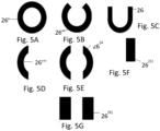
- the clamping device may, in cross-section, have a C-shape, have a U-shape, have a ring-shape with apertures or slots arranged at different angles, or be parallelepipedal or be composed of two or more parallelepipeds.
- clamping pins or rods may be used.
- one, two, three or more clamping pins may be used.
- the shape of the clamp may be variable along its length. For instance, the three or more pins may be connected to a ring.
- the joining device comprises a load measurement system.
- the load measurement system is a load cell.
- the load measurement system may be integrated within the joining device or more particularly the clamping device (internal system) or may be external.
- the load cell measures the clamping force and thus an exact control and command of the clamping force profile can be done.
- the clamping force measurement could be realized via the motor current or by installing a central load cell for both joining and the clamping axis.
- the punch may also comprises its own load measurement system.
- the present invention is also directed to a joining method for joining at least two workpieces with a joining device comprising the following steps of:
- the clamping device can apply a high first pre-determined clamping force to the workpiece, to close any gap which might be present between the workpiece or, during a thermally assisted joining process to optimize the heat transfer between the first and the second workpiece. Due to the design of two axis (clamping axis and joining axis), the clamping force may thus be decreased, and may even thus be cancelled ) by the setting force on a need basis and replaced by the setting force. Depending on the process parameters, materials to be joined and joining element, the setting of the clamping force and setting force may be freely implemented.
- the clamping device comprises a sensor unit providing force, displacement and time data.
- clamping force profile and clamping device displacement profile and/or clamping force profile and joining element displacement profile and/or clamping force and time profile are recorded. All data or values in relation to force or displacement can thus be evaluated. Such data can be used by a control unit to determine the best joining parameter.
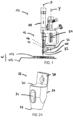
- Fig. 1 shows a perspective view of a joining device 10.
- the joining device 10 is adapted to carry out a method for joining a workpiece arrangement W comprising at least a first and a second workpiece W1, W2 (or sheet) arranged one above the other, together with a joining element.
- the joining device comprises a joining head 12, which can be moved freely in the space by means of a robot (not represented). Eventually, as an alternative, the joining device can be fixed to a structure and the workpieces to be joined moved toward the joining device when needed. Said joining head 12 being for instance mounted on one arm of the robot.
- the joining device 10 or joining head 12 comprises retaining device 14, a punch 16 and a first drive unit 18.
- the retaining device 14, punch 16 and first drive unit 18 are arranged longitudinally extending along a joining axis X.
- the retaining device 14 is adapted to retain a joining element 20.
- the joining element 20 may, for example, be a pin, a screw, a rivet, ... More particularly the joining element 20 may be similar or substantially similar to the joining element described in EP22165638.2 from the applicant.
- the retaining device 14 guides or arranged the joining element 20 along the joining axis X.
- the punch 16 is adapted to drive or actuate the joining element 20 toward the workpiece arrangement W in order to carry out the joining.
- the retaining device 14 and the punch 16 may be both arranged coaxially to the joining axis X.
- the punch 16 may be adapted to penetrate the retaining device 14 in order to drive the joining element 20 toward and into the workpiece arrangement W.
- the punch 16 allows a setting movement of the joining element 20.
- the punch 16 allows a linear setting movement.
- the punch 16 is movable along the joining axis X by the first drive unit 18.
- the first drive unit 18 is an operating module comprising a motor, notably a servo motor or a servo drive adapted to move to a specific position, speed or torque based on an input signal from a controller.
- the first drive unit 18 controls the punch 16 along the joining axis X.
- the first drive unit 18 could also be a hydraulic and/or pneumatic and/or electric drive unit.
- a linear or a rotational drive unit may also be considered.
- the joining device 10 further comprises a clamping device 22 adapted to compress or press the workpiece arrangement in the joining direction.
- the clamping device 22 is movable and controlled by a second drive unit 24.
- the second drive unit 24 is different from the first drive unit 18.
- the second drive unit may be less powerful than the first drive unit 18.
- the second drive unit and the first drive unit may be similar drive units with similar power.
- the second drive unit 24 comprises a servo-electric drive and thus the clamping device 22 is controlled by its own servo-electric drive.
- the second drive unit 24 could also be a hydraulic and/or pneumatic and/or electric drive unit.
- a linear or a rotational drive unit may also be considered.
- the second drive unit 24 moves and control the clamping device 22 along a clamping axis Y.
- the clamping axis Y may be parallel to the joining axis X, but extending from said joining axis at a non-zero distance.
- the clamping axis Y may be coaxial with the joining axis (in such case, for example the first and second drive unit may be arranged one above the other or concentric with each other with for instance a hollow motor).
- the first drive unit may be arranged with an angle with regard to the second drive unit 24. The angle may be between 0 and 90 degrees.
- the clamping device may be driven by its own robot.
- a command can be sent from a control command to the robot controlling the clamping device.
- the robot executes the command and carries out the clamping process independently from the rest of the joining device and setting equipment.
- the setting process with the first drive and the punch can be started (for instance a signal may be sent by the robot to start the setting process or an integrated system may automatically send a command to start the setting process of the joining element).
- the setting and clamping steps may also occur simultaneously.
- a control command can control the first and second drive unit 18, 24 independently and/ or dependently of each other depending on the requirements of the joining process.
- the clamp 26, 26', 26", 26'', 26 (4) , 26 (5) , 26 (6) extends longitudinally between the first end 28 and the second end 30 along the joining axis X.
- a chamfer may be arranged at the first end 28.
- the first end 28 comprises a contact surface 32 adapted to contact the workpiece arrangement W.
- the clamp 26, 26', 26", 26''', 26 (4) , 26 (5) , 26 (6) may comprise on its lateral side a window 34.
- an attachment portion 38 for the attachment of the hollow cylindrical clamp 26 to the rest of the clamping device 22 is arranged on the second end 30, an attachment portion 38 for the attachment of the hollow cylindrical clamp 26 to the rest of the clamping device 22 is arranged.
- the attachment portion 38 extends from the clamp 26, 26', 26", 26''', 26 (4) , 26 (5) , 26 (6) to the rest of the clamping device.
- the attachment portion may at least partially extend parallel to the joining axis X at a non-zero distance from the outer surface of the clamp, in order to avoid any interference with the punch or the retaining device.
- the clamping device 22 may comprise a surface detection unit 40 adapted to detect an upper surface of the workpiece arrangement W.
- the surface detection unit 40 may comprise a laser adapted to measure without contact the distance from the workpiece, or a capacitive sensor or an inductive sensor or any other contactless proximity sensor.
- the surface detection unit 40 may comprise a device for a mechanical or touch measurement for tactile surface recognition. The surface detection may be realized with or without additional component.
- the clamping device 22 may comprise a load measurement system or an integrated load cell 54 adapted to directly measure the clamping force F applied by the clamping device 22 to the workpiece arrangement W.
- the load measurement system 54 will measure the clamping force and send it to a control unit to monitor and/or control the correct implementation of the setting steps (better described below).
- the clamping device 22 comprises a recess or a portion adapted to receive or connect a thermal device 56 directly to the clamping device.
- the thermal device is arranged on the clamping device.
- the thermal device 56 is for instance a plasma torch.
- the plasma torch will thermally assist the joining process.
- Patent publication EP3515632A1 from the applicant explains for instance how the plasma torch may assist the joining process.
- the thermal device may be a laser heating system, and induction heating system, an electric arc or similar equipment.
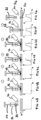
- Fig. 4A to Fig. 4G shows the different possible step of a joining method according to the present invention.
- a clamping force (F) vs. time (t) curve is associated with each schematic representation of the various process steps.
- the joining device 10 is arranged (for instance by the robot mentioned above) above the workpiece arrangement W.
- the joining device 10 does not contact the workpiece arrangement W.
- the workpiece arrangement comprises at least two workpieces (or sheets) W1, W2 arranged one above the other. In other embodiments, more than two workpieces may be used.
- the workpieces may be made in high strength material or brittle cast material or extrusion material.
- an adhesive is provided between the two workpieces.
- the clamping device 22 is moved toward the workpiece arrangement W until it contacts the upper surface of the workpiece arrangement (see Fig. 4B ).
- the upper surface may be recognized by the surface detection unit 40 described above, which can be realized via a function integrated in the already existing parts or which can be an additional component. For instance, a resistance force signal may be sent to a controller to determine the contact with the upper surface of the workpiece. If the joining process is thermally assisted by a plasma torch for instance, the plasma torch 56 may heat the workpiece arrangement, as schematically visible in Fig. 4B .
- a gap (not represented) between the workpieces may be detected by the clamping device 22 by the analysis of the force/time or force/displacement profile of the clamping device, notably though the load measurement system or load cell.
- the clamping device 22 is controlled by a control unit to close the gap by applying for instance a greater clamping force (see for instance fig. 4C ).
- such gap may also be already closed by the initial pre-determined clamping force. Any adhesive retained into the gap is thus displaced to the side.
- a first pre-determined clamping force F1 is then applied to the workpiece arrangement W(see Fig. 4D ).
- the clamping force vs. time curve shows a rather important first pre-determined clamping force F1.
- a great clamping force may be advantageous for allowing heat transmission between the first workpiece and the at least second workpiece.
- the clamping force may remain very limited in order to avoid or limit heat transmission between two workpieces.
- the clamping force F is reduced to prevent the heat transfer to the lower workpiece.
- An excess of heat in the upper workpiece compared to the lower workpiece takes place.
- the clamping force in the setting process the heat flow between the workpieces can be specifically controlled. For example, when the clamping force is reduced, the entire force (comprising the clamping and the setting force) is reduced.
- the clamping force is reduced, during a thermally assisted joining process, the upper workpiece can be heated and the heat transmission of the upper workpiece to the lower workpiece is reduced, such that for instance in case of an upper workpiece in high strength steel, the strength of the material or the flow stress is locally reduced which allows to reduce as well the setting force.
- the clamping force F reaches a second pre-determined clamping force F2 corresponding to the setting step.
- the joining element 20 can be set by the punch 16 within the workpiece arrangement W.
- the joining element 20 may also be set before.
- the joining element 20 is pressed through the at least two workpieces W1, W2 with a determined setting force.
- the effort applied during the setting step to the joining equipment corresponds to the addition of the setting force and the clamping force.
- the clamping force during the setting step may be controlled at a lower of higher level depending on the setting parameters. It is to be noted that the setting force may also be reduced by the thermal device, as described in more details in EP3515632A1 .
- the clamping device 22 is moved back to an exit position (see Fig. 4G ).
Landscapes
- Engineering & Computer Science (AREA)
- Mechanical Engineering (AREA)
- Automatic Assembly (AREA)
Priority Applications (4)
| Application Number | Priority Date | Filing Date | Title |
|---|---|---|---|
| EP23196228.3A EP4520454A1 (fr) | 2023-09-08 | 2023-09-08 | Dispositif d'assemblage avec dispositif de serrage et procédé d'assemblage |
| PCT/EP2024/074870 WO2025051883A1 (fr) | 2023-09-08 | 2024-09-05 | Dispositif de jonction avec dispositif de serrage et procédé de jonction |
| CN202480057418.8A CN121794081A (zh) | 2023-09-08 | 2024-09-05 | 自冲铆接工具和自冲型铆钉的安装方法 |
| PCT/EP2024/074874 WO2025051885A1 (fr) | 2023-09-08 | 2024-09-05 | Outil de rivetage auto-perceur et procédé de réglage d'un rivet de type auto-perceur |
Applications Claiming Priority (1)
| Application Number | Priority Date | Filing Date | Title |
|---|---|---|---|
| EP23196228.3A EP4520454A1 (fr) | 2023-09-08 | 2023-09-08 | Dispositif d'assemblage avec dispositif de serrage et procédé d'assemblage |
Publications (1)
| Publication Number | Publication Date |
|---|---|
| EP4520454A1 true EP4520454A1 (fr) | 2025-03-12 |
Family
ID=88016452
Family Applications (1)
| Application Number | Title | Priority Date | Filing Date |
|---|---|---|---|
| EP23196228.3A Pending EP4520454A1 (fr) | 2023-09-08 | 2023-09-08 | Dispositif d'assemblage avec dispositif de serrage et procédé d'assemblage |
Country Status (2)
| Country | Link |
|---|---|
| EP (1) | EP4520454A1 (fr) |
| WO (1) | WO2025051883A1 (fr) |
Families Citing this family (1)
| Publication number | Priority date | Publication date | Assignee | Title |
|---|---|---|---|---|
| CN120133439A (zh) * | 2025-05-14 | 2025-06-13 | 华东交通大学 | 一种基于热辅助的板料连接装置及方法 |
Citations (14)
| Publication number | Priority date | Publication date | Assignee | Title |
|---|---|---|---|---|
| US4610072A (en) * | 1983-12-21 | 1986-09-09 | Multifastener Corporation | Method of installing a fastener to a panel |
| CH689299A5 (de) | 1994-07-29 | 1999-02-15 | Bodmer Kuesnacht Ag | Verfahren und Vorrichtung zur maschinellen Verformung von Verbindungselementen. |
| DE19905527A1 (de) * | 1999-02-10 | 2000-08-17 | Boellhoff Gmbh | Vorrichtung zum Fügen von Werkstücken aus duktilem Material |
| DE10359879A1 (de) * | 2002-12-20 | 2004-08-12 | Heiko Schmidt | Hydraulische Bearbeitungszange |
| DE10319411A1 (de) * | 2003-04-29 | 2004-11-18 | Kai Sachsenberg | Vorrichtung und Verfahren zum Stanznieten |
| DE102005031917A1 (de) | 2004-09-24 | 2006-04-13 | Böllhoff Verbindungstechnik GmbH | Verfahren zum Fügen und Vorrichtung zum Betätigen eines Fügewerkzeuges |
| JP2007203307A (ja) * | 2006-01-30 | 2007-08-16 | Kawasaki Heavy Ind Ltd | 接合装置 |
| DE102012019809A1 (de) | 2012-10-10 | 2014-04-10 | Daimler Ag | Verfahren zum Stanznieten von Blechen |
| CN103962496A (zh) * | 2014-05-28 | 2014-08-06 | 苏州艾酷玛赫设备制造有限公司 | 手持式自穿刺铆接机 |
| CN104607557A (zh) * | 2015-02-04 | 2015-05-13 | 吉林大学 | 超高强钢板与铝合金板的自冲铆接装置 |
| DE102016007332A1 (de) * | 2016-06-16 | 2017-12-21 | Daimler Ag | Verfahren und Setzgerät zum Eintreiben eines Fügeelements in wenigstens ein Bauteil |
| DE102017106449A1 (de) | 2017-03-24 | 2018-09-27 | Böllhoff Verbindungstechnik GmbH | Mehrstufige Fügevorrichtung und Fügeverfahren dafür |
| EP3515632A1 (fr) | 2016-09-26 | 2019-07-31 | Newfrey LLC | Procédé d'assemblage d'au moins un composant à un second composant sans trou(s) préformé(s) |
| US20210283712A1 (en) * | 2016-08-19 | 2021-09-16 | Ejot Gmbh & Co. Kg | Method for connecting at least two component layers by means of plasma jet pre-drilling of the cover layer |
-
2023
- 2023-09-08 EP EP23196228.3A patent/EP4520454A1/fr active Pending
-
2024
- 2024-09-05 WO PCT/EP2024/074870 patent/WO2025051883A1/fr active Pending
Patent Citations (14)
| Publication number | Priority date | Publication date | Assignee | Title |
|---|---|---|---|---|
| US4610072A (en) * | 1983-12-21 | 1986-09-09 | Multifastener Corporation | Method of installing a fastener to a panel |
| CH689299A5 (de) | 1994-07-29 | 1999-02-15 | Bodmer Kuesnacht Ag | Verfahren und Vorrichtung zur maschinellen Verformung von Verbindungselementen. |
| DE19905527A1 (de) * | 1999-02-10 | 2000-08-17 | Boellhoff Gmbh | Vorrichtung zum Fügen von Werkstücken aus duktilem Material |
| DE10359879A1 (de) * | 2002-12-20 | 2004-08-12 | Heiko Schmidt | Hydraulische Bearbeitungszange |
| DE10319411A1 (de) * | 2003-04-29 | 2004-11-18 | Kai Sachsenberg | Vorrichtung und Verfahren zum Stanznieten |
| DE102005031917A1 (de) | 2004-09-24 | 2006-04-13 | Böllhoff Verbindungstechnik GmbH | Verfahren zum Fügen und Vorrichtung zum Betätigen eines Fügewerkzeuges |
| JP2007203307A (ja) * | 2006-01-30 | 2007-08-16 | Kawasaki Heavy Ind Ltd | 接合装置 |
| DE102012019809A1 (de) | 2012-10-10 | 2014-04-10 | Daimler Ag | Verfahren zum Stanznieten von Blechen |
| CN103962496A (zh) * | 2014-05-28 | 2014-08-06 | 苏州艾酷玛赫设备制造有限公司 | 手持式自穿刺铆接机 |
| CN104607557A (zh) * | 2015-02-04 | 2015-05-13 | 吉林大学 | 超高强钢板与铝合金板的自冲铆接装置 |
| DE102016007332A1 (de) * | 2016-06-16 | 2017-12-21 | Daimler Ag | Verfahren und Setzgerät zum Eintreiben eines Fügeelements in wenigstens ein Bauteil |
| US20210283712A1 (en) * | 2016-08-19 | 2021-09-16 | Ejot Gmbh & Co. Kg | Method for connecting at least two component layers by means of plasma jet pre-drilling of the cover layer |
| EP3515632A1 (fr) | 2016-09-26 | 2019-07-31 | Newfrey LLC | Procédé d'assemblage d'au moins un composant à un second composant sans trou(s) préformé(s) |
| DE102017106449A1 (de) | 2017-03-24 | 2018-09-27 | Böllhoff Verbindungstechnik GmbH | Mehrstufige Fügevorrichtung und Fügeverfahren dafür |
Also Published As
| Publication number | Publication date |
|---|---|
| WO2025051883A1 (fr) | 2025-03-13 |
Similar Documents
| Publication | Publication Date | Title |
|---|---|---|
| US6543115B1 (en) | Process and device for joining by punching and riveting | |
| KR102874667B1 (ko) | 블라인드 체결구용 세팅 도구 | |
| EP4520454A1 (fr) | Dispositif d'assemblage avec dispositif de serrage et procédé d'assemblage | |
| US11135637B2 (en) | Method for determining the quality of a joint, and control method for a process of joining a plurality of metal sheets by means of a joining device | |
| EP3653367B1 (fr) | Appareil de fixation et procédé de détermination de la qualité d'un élément de fixation | |
| JP2024149583A (ja) | 摩擦攪拌点接合装置及び摩擦攪拌点接合方法 | |
| JP6338151B2 (ja) | 電気溶接装置 | |
| CA3128916C (fr) | Machine de raccord ajustable | |
| US10646950B2 (en) | Spot welding method and device | |
| KR102280608B1 (ko) | 셀프 피어싱 리벳팅 장치 및 셀프 피어싱 리벳팅 방법 | |
| US8549723B2 (en) | Method and apparatus for squeezing parts such as fasteners | |
| EP1657018B1 (fr) | Méthode et appareil d'équilibrage automatique pour une pince de soudage | |
| EP3653893B1 (fr) | Appareil de fixation | |
| WO2025051885A1 (fr) | Outil de rivetage auto-perceur et procédé de réglage d'un rivet de type auto-perceur | |
| KR102637245B1 (ko) | 마찰교반 점접합 장치 및 그 운전 방법 | |
| EP4520453A1 (fr) | Procédé d'assemblage et dispositif d'assemblage pour assembler des pièces | |
| EP2908966B1 (fr) | Structure de cadre en c conçue pour fournir une compensation à la flexion et procédé associé | |
| KR101505910B1 (ko) | 셀프 피어싱 리벳 장치 | |
| KR101543244B1 (ko) | 리벳 공급장치 및 이를 포함하는 셀프 피어싱 리벳 시스템 | |
| US20230278131A1 (en) | Welding gun with an actuator on a fixed electrode | |
| US12059722B2 (en) | Clamping method and clamping device | |
| US20240367216A1 (en) | Method of producing a riveted joint | |
| EP4596137A1 (fr) | Procédé d'assemblage pour assembler des pièces et dispositif d'assemblage | |
| CN219597987U (zh) | 一种铆接装置 | |
| EP1127634B1 (fr) | Système de rivetage autoperforant |
Legal Events
| Date | Code | Title | Description |
|---|---|---|---|
| PUAI | Public reference made under article 153(3) epc to a published international application that has entered the european phase |
Free format text: ORIGINAL CODE: 0009012 |
|
| STAA | Information on the status of an ep patent application or granted ep patent |
Free format text: STATUS: THE APPLICATION HAS BEEN PUBLISHED |
|
| AK | Designated contracting states |
Kind code of ref document: A1 Designated state(s): AL AT BE BG CH CY CZ DE DK EE ES FI FR GB GR HR HU IE IS IT LI LT LU LV MC ME MK MT NL NO PL PT RO RS SE SI SK SM TR |
|
| STAA | Information on the status of an ep patent application or granted ep patent |
Free format text: STATUS: REQUEST FOR EXAMINATION WAS MADE |
|
| 17P | Request for examination filed |
Effective date: 20250911 |
|
| STAA | Information on the status of an ep patent application or granted ep patent |
Free format text: STATUS: EXAMINATION IS IN PROGRESS |
|
| 17Q | First examination report despatched |
Effective date: 20260127 |