EP1657018B1 - Méthode et appareil d'équilibrage automatique pour une pince de soudage - Google Patents
Méthode et appareil d'équilibrage automatique pour une pince de soudage Download PDFInfo
- Publication number
- EP1657018B1 EP1657018B1 EP04380223A EP04380223A EP1657018B1 EP 1657018 B1 EP1657018 B1 EP 1657018B1 EP 04380223 A EP04380223 A EP 04380223A EP 04380223 A EP04380223 A EP 04380223A EP 1657018 B1 EP1657018 B1 EP 1657018B1
- Authority
- EP
- European Patent Office
- Prior art keywords
- compensating
- actuator
- gun
- welding
- horns
- Prior art date
- Legal status (The legal status is an assumption and is not a legal conclusion. Google has not performed a legal analysis and makes no representation as to the accuracy of the status listed.)
- Expired - Lifetime
Links
- 238000003466 welding Methods 0.000 title claims abstract description 102
- 238000000034 method Methods 0.000 title claims abstract description 32
- 210000000080 chela (arthropods) Anatomy 0.000 claims abstract description 75
- 230000033001 locomotion Effects 0.000 claims description 55
- 230000008859 change Effects 0.000 claims description 10
- 230000005540 biological transmission Effects 0.000 claims description 6
- 230000004044 response Effects 0.000 claims description 3
- 230000000694 effects Effects 0.000 description 7
- 230000009471 action Effects 0.000 description 3
- 238000010276 construction Methods 0.000 description 2
- 238000005493 welding type Methods 0.000 description 2
- 238000001514 detection method Methods 0.000 description 1
- 239000012530 fluid Substances 0.000 description 1
- 238000005259 measurement Methods 0.000 description 1
- 230000008569 process Effects 0.000 description 1
Images


Classifications
-
- B—PERFORMING OPERATIONS; TRANSPORTING
- B23—MACHINE TOOLS; METAL-WORKING NOT OTHERWISE PROVIDED FOR
- B23K—SOLDERING OR UNSOLDERING; WELDING; CLADDING OR PLATING BY SOLDERING OR WELDING; CUTTING BY APPLYING HEAT LOCALLY, e.g. FLAME CUTTING; WORKING BY LASER BEAM
- B23K11/00—Resistance welding; Severing by resistance heating
- B23K11/30—Features relating to electrodes
- B23K11/31—Electrode holders and actuating devices therefor
- B23K11/314—Spot welding guns, e.g. mounted on robots
- B23K11/315—Spot welding guns, e.g. mounted on robots with one electrode moving on a linear path
-
- B—PERFORMING OPERATIONS; TRANSPORTING
- B23—MACHINE TOOLS; METAL-WORKING NOT OTHERWISE PROVIDED FOR
- B23K—SOLDERING OR UNSOLDERING; WELDING; CLADDING OR PLATING BY SOLDERING OR WELDING; CUTTING BY APPLYING HEAT LOCALLY, e.g. FLAME CUTTING; WORKING BY LASER BEAM
- B23K11/00—Resistance welding; Severing by resistance heating
- B23K11/24—Electric supply or control circuits therefor
- B23K11/25—Monitoring devices
- B23K11/252—Monitoring devices using digital means
- B23K11/253—Monitoring devices using digital means the measured parameter being a displacement or a position
-
- B—PERFORMING OPERATIONS; TRANSPORTING
- B23—MACHINE TOOLS; METAL-WORKING NOT OTHERWISE PROVIDED FOR
- B23K—SOLDERING OR UNSOLDERING; WELDING; CLADDING OR PLATING BY SOLDERING OR WELDING; CUTTING BY APPLYING HEAT LOCALLY, e.g. FLAME CUTTING; WORKING BY LASER BEAM
- B23K11/00—Resistance welding; Severing by resistance heating
- B23K11/24—Electric supply or control circuits therefor
- B23K11/25—Monitoring devices
- B23K11/252—Monitoring devices using digital means
- B23K11/255—Monitoring devices using digital means the measured parameter being a force
-
- B—PERFORMING OPERATIONS; TRANSPORTING
- B23—MACHINE TOOLS; METAL-WORKING NOT OTHERWISE PROVIDED FOR
- B23K—SOLDERING OR UNSOLDERING; WELDING; CLADDING OR PLATING BY SOLDERING OR WELDING; CUTTING BY APPLYING HEAT LOCALLY, e.g. FLAME CUTTING; WORKING BY LASER BEAM
- B23K11/00—Resistance welding; Severing by resistance heating
- B23K11/30—Features relating to electrodes
- B23K11/31—Electrode holders and actuating devices therefor
- B23K11/311—Electrode holders and actuating devices therefor the actuating device comprising an electric motor
-
- B—PERFORMING OPERATIONS; TRANSPORTING
- B23—MACHINE TOOLS; METAL-WORKING NOT OTHERWISE PROVIDED FOR
- B23K—SOLDERING OR UNSOLDERING; WELDING; CLADDING OR PLATING BY SOLDERING OR WELDING; CUTTING BY APPLYING HEAT LOCALLY, e.g. FLAME CUTTING; WORKING BY LASER BEAM
- B23K11/00—Resistance welding; Severing by resistance heating
- B23K11/30—Features relating to electrodes
- B23K11/31—Electrode holders and actuating devices therefor
- B23K11/317—Equalizing; Balancing devices for electrode holders
Definitions
- the present invention concerns a welding pincer gun automatic compensation method and apparatus according to the preambles of claims 1 and 3.
- a method and apparatus are known from US 598846-B1 .
- the apparatus of the invention includes a compensating actuator being made up of an electric motor and programmable, electronic control means, and the method comprises controlling the position and/or the feed current being required by the compensating electric motor based on signals being generated by sensing means being associated to the compensating motor.
- the welding pincer guns of the type in question comprise a couple of electrode-supporting horns being fitted to a supporting base, said horns being able to carry out a relative motion and to thus mutually approach the electrodes or move them away from each other under the action of a main actuator.
- An electronic control system controls said actuator in order to close the welding pincer gun till having brought the electrodes to a nipping position upon a workpiece and to thereupon apply a pressure or a pressure sequence on the workpiece during a predetermined period of time while simultaneously controlling the application of a welding current.
- Said supporting base is usually fitted to the end of a robotic arm being controlled by said electronic control system in order to move the supporting base and successively position the welding pincer gun at the points where welds are to be effected.
- a compensating actuator links one of the horns with respect to the base and its actuation allows to change and/or fix the assembly being made up of the two horns forming the welding pincer gun with respect to the base, and to compensate the effect of external, forces such as the inertial or gravitational forces on the horns in different positions of the welding pincer gun.
- a drawback of this type of welding pincer guns resides in the fact that one of the electrodes inevitably (even if slightly) contacts the workpiece before the other one does, and the closing force being applied to the horns can deform the workpiece before the application of the welding pressure to this latter.
- US 5988486-B1 discloses a welding pincer gun automatic compensation method wherein a welding gun comprises a couple of electrodes fitted to respective horns mutually linked in such a way that they are apt to carry out a relative motion, a main actuator between both horns, a link between said horns, a compensating actuator and electronic control means adapted to control the operation of said main and compensating actuators and other welding parameters according to a number of given steps.
- the automatic welding pincer gun as well as the method disclosed in US 5988486-B1 are similar to the ones proposed in this invention except in that in this prior art the welding device generates a change in the control mode of the motor of the compensating actuator from a position control mode to a current control mode only as a consequence of the detection of a contact between one of the electrodes and the work piece.
- the present invention contributes to obviate the drawbacks of the prior art systems having been described above by providing an automatic compensation method for controlling the motions of a welding pincer gun, as well as an apparatus for implementing said method.
- the method is apt to be applied both with "X"-type welding pincer guns and with "C”-type welding pincer guns as per the following detailed description, the apparatus hence contemplating both possibilities.
- the welding pincer gun automatic compensation method as per the instant invention is to be applied with a welding pincer gun of a conventional type generally comprising a couple of electrodes being fitted to respective horns being mutually linked in such a way that they are apt to carry out a relative motion, and a main actuator being incorporated between both horns in order to bring about said relative motion between an open position wherein the electrodes are spaced apart, a pre-weld position wherein the electrodes are close to a workpiece, and a closed position wherein the electrodes are in contact with said workpiece and exert a pressure on it.
- the welding pincer gun is of the type besides comprising a link between at least one of said horns being the herein so-called compensating horn, and a supporting base, said link allowing said horn to carry out a relative motion with respect to said base.
- the welding pincer gun does as well comprise a compensating actuator, this latter including an electric motor and being apt to immobilise said compensating horn with respect to said supporting base or to change its position.
- an immobilisation or a change of relative position of the compensating horn with respect to the supporting base involves an immobilisation or a change of relative position of the whole welding pincer gun being formed by the two horns regardless of the relative position between them.
- the welding pincer gun is finally of the type including electronic control means being adapted to control the operation of said main and compensating actuators and other welding parameters.
- the method of the present invention is characterised in that it comprises the following steps. Initially a) establishing a predetermined relative position between said welding pincer gun in the open position and a welding point where a weld is to be effected in said workpiece. This relative position can be reached either through a shifting motion of the welding pincer gun or of the workpiece or through a combination of both.
- the method thereupon comprises b) situating the horns in said pre-weld position by means of an approaching travel being carried out by the main actuator under a command of said control means while the welding pincer gun is maintained in said predetermined relative position by said control means maintaining the compensating actuator motor in a position control mode regardless of the current being consumed by it.
- the next step c) comprises sensing by means of the control means the current being consumed by the compensating actuator motor when this latter is in said position control mode and thereupon switching the control to a current control mode wherein the control means maintain the compensating actuator motor in a state of irrespective of its angular position consuming the current having been previously sensed.
- the method thereupon proceeds to d) situate the horns in said closed position by means of a welding travel being carried out by the main actuator under a command of the control means while the compensating actuator motor remains in said current control mode.
- the control means proceed to e) apply welding parameters of a conventional type, such as a welding current and a welding pressure or pressure sequence.
- the method finally comprises after the weld returning the horns to the open position by means of a return travel driven by the main actuator, and returning the control of the compensating actuator motor to the position control mode.
- the welding pincer gun automatic compensation apparatus as per the present invention includes a welding pincer gun of a conventional type having been described above in relation to the method and is characterised in that it does besides comprise an angular position sensor being adapted to sense the angular position of said compensating actuator motor and a current sensor for sensing the current being consumed by said compensating actuator motor.
- the above-mentioned electronic control means are adapted to control the operation of the compensating actuator motor as per a position control mode wherein the compensating actuator motor is maintained in a predetermined constant angular position irrespective of the current being consumed by it, and as per a current control mode wherein the compensating actuator motor is maintained in a state of consuming a constant current irrespective of its angular position. This constant current has been previously sensed as the current being consumed by the compensating actuator motor during the position control mode.
- the welding pincer gun can be adapted to be fitted to the end of a robotic arm being able to move the welding pincer gun in order to position it with respect to the workpiece in different spatial orientations and/or at successive welding points.
- the motions of said robotic arm are controlled by the electronic control means as per previously programmed sequences.
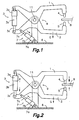
- the apparatus being diagrammatically illustrated in Figs. 1 through 3 and shown in Fig. 7 comprises an "X"-type welding pincer gun
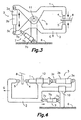
- the apparatus being diagrammatically illustrated in Figs. 4 through 6 and shown in Fig. 8 comprises an "C"-type welding pincer gun.
- Both types of welding pincer gun do nevertheless generically have some common features as follows: Both the "X"-type welding pincer gun and the "C"-type welding pincer gun comprise a couple of electrode-supporting horns 1, 2 being mutually linked in such a way that they are apt to carry out a relative motion between each other.
- a main actuator 3 is operatively incorporated between both horns 1, 2 in order to carry out the actuation bringing about said relative motion between the following positions: an open position ( Figs. 1 and 4 ) wherein the electrodes 4, 5 are spaced apart; a pre-weld position ( Figs. 2 and 5 ) wherein the electrodes 4, 5 are close to a workpiece 8 to be welded; and a closed position or welding position ( Figs. 3 and 6 ) wherein the electrodes 4, 5 are in contact with said workpiece 8 and exert a pressure on it in order to effect the weld.
- the above-mentioned link between the horns 1, 2 comprises a pin-jointed connection 11 allowing to carry out a pivoting motion around an axis being transversally arranged with respect to the travelling direction of the electrodes 4, 5, said pin-jointed connection allowing the horns 1, 2 to carry out a pivoting relative motion between each other.
- the apparatus as per the exemplary embodiment being shown in Figs. 4 through 6 and in Fig. 8 , i.e.
- the above-mentioned link between the horns 1, 2 comprises a linear guide 12 extending in a direction being parallel to or aligned with the travelling direction of the electrodes 4, 5, said linear guide allowing the horns 1, 2 to carry out a translating relative motion between each other.
- the main actuator 3 preferably includes an electric motor 3a and a transmission 3b being apt to turn a turning motion of the electric motor 3a into a linear shifting motion of a rod 3c, although for the purposes of implementing the method of the invention any other type of actuator could be used, such as a fluid-operated cylinder.
- An actuator being based on an electric motor does in any case offer more control possibilities and obviates the need of supplying compressed air or another compressed fluid.
- a motor housing 3a is linked to one 1 of the horns, and a distal end of the rod 3c is linked to the other horn 2.
- One of the horns herein being the so-called compensating horn 2 is linked to a supporting base 6 through a link allowing said horn to carry out a relative motion with respect to said base, in such a way that the whole welding pincer gun being formed by the two horns 1, 2 and the main actuator 3 can effect a motion with respect to the supporting base 6 without this affecting the mutually relative position of the two horns 1, 2, this latter only being determined by the position of the main actuator 3, or equivalently by the angular position of the motor 3a or of another turning member of the main actuator 3, said position being easily controllable by means of an angular position sensor being associated to electronic control means (not shown).
- said link between the compensating horn 2 and the supporting base 6 comprises a pin-jointed connection 9 allowing to carry out a pivoting motion around an axis being transversally arranged with respect to the travelling direction of the electrodes 4, 5, said pin-jointed connection allowing the compensating horn 2 to carry out a pivoting relative motion with respect to the supporting base 6.
- said link between the compensating horn 2 and the supporting base 6 comprises a linear guide 10 extending in a direction being parallel to or aligned with the travelling direction of the electrodes 4, 5, said guide allowing the compensating horn 2 to carry out a translating relative motion with respect to said supporting base 6.
- the device includes a compensating actuator 7 being arranged between the previously cited compensating horn 2 and the base 6 in order to immobilise the compensating horn 2, i.e. the whole welding pincer gun being formed by the two horns 1, 2 and the main actuator 3, with respect to the base 6, or to change its relative position.
- the compensating actuator 7 must in this case indispensably include an electric motor.
- the compensating actuator 7 does for such a purpose comprise an electric motor 7a being connected to a transmission 7b being adapted to transform a turning motion of the motor 7a into a linear shifting motion of a rod 7c, a motor housing 7a being linked to a point being fixed with respect to the supporting base 6, a distal end of the rod 7c being linked to the compensating horn 2.
- the supporting base 6 is usually designed to be fitted to the end of a robotic arm (not shown) being able to move the welding pincer gun to thus position it with respect to the workpiece 8 in different spatial orientations and/or at successive welding points. It is alternatively also usual to fixedly attach the supporting base 6 to a structure so that the welding pincer gun remains stationary and to arrange a robotic arm so as to position the workpiece 8 with respect to the welding pincer gun. It is also possible to arrange a pair of robotic arms or other shifting means so as to move both the welding pincer gun and the workpiece in order to establish a predetermined relative position between both of them.
- Programmable, electronic control means are provided for controlling the motions of said robotic system, as well as the motions for the opening and closing of the horns 1, 2 of the welding pincer gun, the pressure being exerted by the electrodes 4, 5 on the workpiece 8, said pressure being generated by the force of the main actuator 3, the compensating motions being carried out by the compensating actuator 7, and the application of a welding current to the electrodes 4, 5 while these latter exert said pressure on the workpiece 8.
- the electronic control means do for such a purpose comprise several sensing means (not shown) being associated to different components of the apparatus.
- the control means of the apparatus of the invention do for example comprise at least one angular position sensor being adapted to sense the angular position of said motor 7a of the compensating actuator 7 and one current sensor for sensing the current being consumed by said motor 7a of the compensating actuator 7.
- These sensing means are able to generate signals being representative of the position of the rotor and of the current intensity being consumed by the motor 7a, and to send these signals to processing means pertaining to the control means and being able to process the received signals and to generate control commands and send them to the motor 7a of the compensating actuator 7 in order to thus control its angular position and/or the feed current to be supplied to it.
- the electronic control means are adapted for controlling the operation of the motor 7a of the compensating actuator 7 as per two different control modes: a position control mode wherein the motor 7a of the compensating actuator 7 is maintained in a predetermined constant angular position irrespective of the current being consumed by it; and a current control mode wherein the motor 7a of the compensating actuator 7 is maintained in a state of consuming a constant current irrespective of its angular position.
- Said constant current is previously sensed during the position control mode as per the method of the invention being described in detail as follows.
- the automatic compensation method of the invention for a welding pincer gun comprises the following steps.
- a) establishing a predetermined relative position between said welding pincer gun in the open position and a welding point where a weld is to be effected in said workpiece 8 ( Figs. 1 and 4 ).
- said relative position can be established either through a shifting motion of the welding pincer gun or of the workpiece or through a combination of both.
- Said approaching travel is carried out while the welding pincer gun is maintained in said predetermined relative position by the compensating actuator 7 being governed by said control means as per the above-mentioned position control mode.
- the method does thereupon comprise c) sensing by means of the previously cited current sensor of the control means the current being consumed by the motor 7a of the compensating actuator 7 when said motor is being controlled as per the position control mode, and thereupon switching the control to said current control mode wherein the control means maintain the motor 7a of the compensating actuator 7 in a state of constantly consuming the current having been previously sensed.
- the motor 7a of the compensating actuator 7 is in a position to in a positive or in a negative sense effect changes of its angular position for example in response to a force being external to the system being formed by the compensating horn 2, the supporting base 6 and the compensating actuator 7, provided that the motor 7a exactly consumes the previously sensed current.
- the workpiece 8 hence exerts a reaction force on the electrode 4, 5 being involved in said contact, said reaction force being added to or subtracted from the force being exerted by the compensating actuator 7 based on the constant current feeding it, and the motor 7a of the compensating actuator 7 operates in one or another sense so as to thus compensate said reaction force till reaching a balance state, the force being exerted by the electrode 4, 5 on the workpiece thus being prevented from actually deforming it.
- the method then proceeds to d) situate the horns 1, 2 in said closed position ( Figs. 3 and 6 ) by means of a welding travel being carried out by the main actuator 3 under a command of the control means while the motor 7a of the compensating actuator 7 remains in said current control mode, the compensating operation having been initiated in the previous step c) being therefore continued.
- the control means proceed to apply the previously programmed welding parameters.
- the method finally comprises e) returning the horns 1, 2 to the open position by means of a return travel driven by the main actuator 3, and returning the control of the motor 7a of the compensating actuator 7 to the position control mode.
Landscapes
- Engineering & Computer Science (AREA)
- Mechanical Engineering (AREA)
- Robotics (AREA)
- Resistance Welding (AREA)
Claims (11)
- Méthode de compensation automatique de pistolet à pinces pour soudage dans laquelle ce pistolet à pinces pour soudage est du genre comportant:- une paire d'électrodes (4,5) étant rapportée sur des bras respectifs (1,2) qui sont reliés entre eux de sorte qu'ils sont aptes pour effectuer un mouvement relatif;- un actionneur principal (3) étant incorporé entre ces bras (1, 2) afin d'effectuer ce mouvement relatif entre une position ouverte dans laquelle les électrodes (4,5) sont écartées, une position préalable au soudage dans laquelle les électrodes (4, 5) sont près d'une pièce en cours de travail (8) et une position fermée dans laquelle les électrodes (4, 5) sont en contact avec cette pièce en cours de travail (8) et exerce une pression sur celle-ci;- un raccord (9, 10) entre au moins un de ces bras qui sont notamment les bras désignés bras de compensation (2) et une base de support (6), ce raccord permettant que ce bras effectue un mouvement relatif par rapport à cette base;- un actionneur de compensation (7), ce dernier comportant un moteur électrique (7a) et étant apte pour immobiliser ce bras de compensation (2) par rapport à cette base de support (6) ou pour changer sa position; et- des moyens de contrôle électroniques étant adaptés pour contrôler le fonctionnement de ces actionneurs principaux et de compensation (3,7) et d'autres paramètres de soudage;caractérisée en ce qu'elle comporte les étapes suivantes:a) à travers un mouvement de déplacement soit du pistolet à pinces pour soudage soit de la pièce en cours de travail ou bien une combinaison des deux en établissant une position relative prédéterminée entre ce pistolet à pinces de soudage dans la position ouverte et un point de soudure où il faut effectuer le soudage sur cette pièce en cours de travail (8);b) situé les bras (1,2) à cette position préalable au soudage au moyen d'un déplacement de rapprochement effectué par l'actionneur principal (3) sous une commande de ces moyens de contrôle tandis que le pistolet à pinces de soudage est maintenu dans cette position relative prédéterminée par l'actionneur de compensation (7) contrôlés par ces moyens de contrôle selon un mode de contrôle de position dans lequel ce moteur (7a) de l'actionneur de compensation (7) est maintenu dans une position angulaire constante indépendamment du courant qu'il consomme;c) détecter avec les moyens de contrôle le courant qui est consommé par le moteur (7a) de l'actionneur de compensation (7) lorsque ce moteur est contrôlé selon ce mode de contrôle de position, et avant qu'une quelconque des électrodes (4, 4) soit entrée en contact avec la pièce en cours de travail (8) et ensuite commuter le contrôle à un mode de contrôle de courant dans lequel les moyens de contrôle maintienent le moteur (7a) de l'actionneur de compensation (7) dans un état de consommation d'un courant constant étant égal au courant ayant été préalablement détecté, ce moteur étant dans cet état capable de changer sa position angulaire comme réponse à une force externe;d) situer les bras (1,2) dans cette position fermée au moyen d'un déplacement de soudage effectué par l'actionneur principal (3) sous une commande des moyens de contrôle tandis que le moteur (7a) de l'actionneur de compensation (7) reste dans ce mode de contrôle de courant et appliquer quelques paramètres de soudage; ete) après le soudage, retourner les bras (1,2) à une position ouverte au moyen d'un déplacement de retour entraîné par l'actionneur principal (3) et retourner le contrôle du moteur (7a) de l'actionneur de compensation (7) au mode de contrôle de position.
- Méthode conformément à la revendication 1, caractérisée en ce que ce pistolet à pince pour soudage est intégré dans un système robotique et ce mouvement de déplacement du pistolet à pinces pour soudage ou de la pièce en cours de travail ou une combinaison des deux afin d'établir cette position relative prédéterminée entre le pistolet à pinces de soudage et ce point de soudage sur la pièce en cours de travail (8) est effectué par au moins un bras robotique sous les commandes des moyens de contrôle basés sur des instructions préalablement programmées.
- Appareil pour la compensation automatique d'un pistolet à pinces pour soudage dans lequel ce pistolet à pince pour soudage est du genre comportant:- une paire d'électrodes (4,5) étant rapportée sur des bras respectifs (1,2) qui sont reliés entre eux de sorte qu'ils sont aptes pour effectuer un mouvement relatif;- un actionneur principal (3) étant incorporé entre ces bras (1, 2) afin d'effectuer ce mouvement relatif entre une position ouverte dans laquelle les électrodes (4,5) sont écartées, une position préalable au soudage dans laquelle les électrodes (4, 5) sont près d'une pièce en cours de travail (8) et une position fermée dans laquelle les électrodes (4, 5) sont en contact avec cette pièce en cours de travail (8) et exerce une pression sur celle-ci;- un raccord (9, 10) entre au moins un de ces bras qui sont notamment les bras désignés bras de compensation (2) et une base de support (6), ce raccord permettant que ce bras effectue un mouvement relatif par rapport à cette base;- un actionneur de compensation (7), ce dernier comportant un moteur électrique (7a) et étant apte pour immobiliser ce bras de compensation (2) par rapport à cette base de support (6) ou de changer sa position; et- des moyens de contrôle électroniques étant adaptés pour contrôler le fonctionnement de ces actionneurs principaux et de compensation (3,7) et d'autres paramètres de soudage;caractérisé en ce qu'il comporte un détecteur de position angulaire étant adapté pour détecter la position angulaire de ce moteur (7a) de l'actionneur de compensation (7) et un détecteur de courant pour détecter le courant consommé par le moteur (7a) de l'actionneur de compensation (7), ces moyens de contrôle électroniques étant adaptés pour contrôler le fonctionnement du moteur (7a) de l'actionneur de compensation (7) selon au moins deux modes de contrôle:- un mode de contrôle de position dans lequel le moteur (7a) de l'actionneur de compensation (7) est maintenu dans une position angulaire constante prédéterminée indépendamment du courant qu'il consomme; et- un mode de contrôle de courant dans lequel le moteur (7a) de l'actionneur de compensation (7) est maintenu dans un état de consommation de courant constante ayant été préalablement détectée durant le mode de contrôle de position, ce moteur étant dans cet état capable de changer sa position angulaire comme réponse à une force externe, les moyens de contrôle étant en plus adaptés pour effectuer la méthode conformément au revendications 1 ou 2.
- Un appareil conformément à la revendication 3, caractérisé en ce que ledit raccord entre les bras (1,2) comporte une articulation (11) permettant d'effectuer un mouvement pivotant autour d'un axe étant transversalement aménagé par rapport à la direction de déplacement des électrodes (4,5), cette articulation permettant que les bras (1,2) effectuent un mouvement relatif pivotant entre eux.
- Un appareil conformément à la revendication 4, caractérisée en ce que ce raccord entre le bras de compensation (2) de cette base de support (6) comprend une articulation (9) permettant d'effectuer un mouvement pivotant autour d'un axe étant transversalement aménagé par rapport à la direction de déplacement des électrodes (4,5), cette articulation permettant que les bras (1,2) effectuent un mouvement pivotant relatif entre eux et le bras de compensation (2) pour effectuer un mouvement pivotant relatif par rapport à la base de support (6).
- Un appareil conformément à la revendication 3, caractérisé en ce que ledit raccord entre les bras (1,2) et ce raccord entre ce bras de compensation (2) et cette base de support (6) comporte une articulation (9, 11) permettant d'effectuer un mouvement pivotant autour d'un axe étant transversalement aménagé par rapport à la direction de déplacement des électrodes (4,5), cette articulation permettant que le bras de compensation (2) effectue un mouvement pivotant relatif par rapport à la base de support (6).
- Un appareil conformément à la revendication 3, caractérisé en ce que ledit raccord entre les bras (1,2) comporte un guidage linéaire (12) qui s'étend dans une direction parallèle où alignée à la direction de déplacement des électrodes (4,5), ce guidage linéaire permettant que les bras (1,2) effectuent un mouvement de translation relatif entre eux.
- Un appareil conformément à la revendication 7, caractérisée en ce que ce raccord entre le bras de compensation (2) et cette base de support (6) comporte un guidage linéaire (10) s'étendant dans une direction parallèle ou alignée à la direction de déplacement des électrodes (4,5) ce guidage permettant que le bras de compensation (2) effectue un mouvement de translation relatif par rapport à cette base de support (6).
- Un appareil conformément à la revendication 3, caractérisé en ce que cet actionneur de compensation (7) comporte une transmission (7b) adaptée pour entraîner en rotation le moteur électrique (7a) avec un mouvement de déplacement linéaire d'une tige (7c).
- Un appareil conformément à la revendication 3, caractérisé en ce que cet actionneur principal (3) comporte un moteur électrique (3a) et une transmission (3b) étant adaptés pour entraîner un mouvement de rotation du moteur électrique (3a) en un mouvement de déplacement linéaire d'une tige (3c).
- Un appareil conformément à la revendication 3, caractérisée en ce que ce pistolet à pinces pour soudage est intégré dans un système robotique étant contrôlé par ces moyens de contrôle et comportant au moins un bras robotique pour effectuer un mouvement de déplacement du pistolet à pinces pour soudage ou de la pièce en cours de travail ou une combinaison des deux afin d'établir une position relative prédéterminée entre le pistolet à pinces pour soudage et un point de soudage sur la pièce en cours de travail (8).
Priority Applications (3)
| Application Number | Priority Date | Filing Date | Title |
|---|---|---|---|
| AT04380223T ATE419948T1 (de) | 2004-11-10 | 2004-11-10 | Automatische ausgleichsvorrichtung und automatisches ausgleichsverfahren für eine schwei zange |
| DE602004018937T DE602004018937D1 (de) | 2004-11-10 | 2004-11-10 | Automatische Ausgleichsvorrichtung und automatisches Ausgleichsverfahren für eine Schwei zange |
| EP04380223A EP1657018B1 (fr) | 2004-11-10 | 2004-11-10 | Méthode et appareil d'équilibrage automatique pour une pince de soudage |
Applications Claiming Priority (1)
| Application Number | Priority Date | Filing Date | Title |
|---|---|---|---|
| EP04380223A EP1657018B1 (fr) | 2004-11-10 | 2004-11-10 | Méthode et appareil d'équilibrage automatique pour une pince de soudage |
Publications (2)
| Publication Number | Publication Date |
|---|---|
| EP1657018A1 EP1657018A1 (fr) | 2006-05-17 |
| EP1657018B1 true EP1657018B1 (fr) | 2009-01-07 |
Family
ID=34931871
Family Applications (1)
| Application Number | Title | Priority Date | Filing Date |
|---|---|---|---|
| EP04380223A Expired - Lifetime EP1657018B1 (fr) | 2004-11-10 | 2004-11-10 | Méthode et appareil d'équilibrage automatique pour une pince de soudage |
Country Status (3)
| Country | Link |
|---|---|
| EP (1) | EP1657018B1 (fr) |
| AT (1) | ATE419948T1 (fr) |
| DE (1) | DE602004018937D1 (fr) |
Families Citing this family (11)
| Publication number | Priority date | Publication date | Assignee | Title |
|---|---|---|---|---|
| DE102006056051B4 (de) * | 2006-11-28 | 2018-09-20 | Robert Bosch Gmbh | Roboter mit Steuerung für Zusatzachsen |
| JP4233584B2 (ja) * | 2007-06-18 | 2009-03-04 | ファナック株式会社 | スポット溶接ロボットの位置決め方法 |
| US8304681B2 (en) | 2007-09-13 | 2012-11-06 | Comau, Inc. | Universal weld gun configuration |
| DE102007062384A1 (de) * | 2007-12-22 | 2009-06-25 | Robert Bosch Gmbh | Einrichtung mit integriertem Lagesensor |
| WO2012041787A1 (fr) * | 2010-10-01 | 2012-04-05 | Norgren Gmbh | Procédé et appareil d'équilibrage d'un bras d'électrode d'un dispositif de soudage avec détermination de pression d'équilibre différentielle |
| JP5965146B2 (ja) * | 2011-12-27 | 2016-08-03 | 富士重工業株式会社 | スポット溶接装置の異常検出方法 |
| JP5965145B2 (ja) * | 2011-12-27 | 2016-08-03 | 富士重工業株式会社 | スポット溶接装置の作動制御方法 |
| JP5922926B2 (ja) * | 2011-12-27 | 2016-05-24 | 富士重工業株式会社 | スポット溶接装置の加圧制御方法 |
| CN105382397A (zh) * | 2015-12-21 | 2016-03-09 | 合肥亿恒机械有限公司 | 一种带冷却水管路的x形自动焊钳 |
| CN108098127B (zh) * | 2018-02-06 | 2024-08-09 | 武汉汉孚装备技术有限公司 | 焊钳修模补偿装置及其方法及焊钳装置 |
| CN117464572B (zh) * | 2023-12-28 | 2024-03-05 | 沈阳华钛实业有限公司 | 一种封闭式水切割机床用上下料夹持机械臂 |
Family Cites Families (4)
| Publication number | Priority date | Publication date | Assignee | Title |
|---|---|---|---|---|
| DE3927435A1 (de) * | 1989-08-19 | 1991-02-21 | Ferdinand Schwob | Verfahren zur regelung des gewichtsausgleichs fuer den zangenkoerper von schiebe- oder scherenschweisszangen |
| US5988486A (en) | 1997-03-11 | 1999-11-23 | Honda Giken Kogyo Kabushiki Kaisha | Method of controlling electrode force of spot welding gun |
| FR2822743B1 (fr) * | 2001-03-29 | 2003-08-08 | Aro | Pince-robot d'assemblage a dispositif de detalonnage et d'equilibrage auto-adaptatif |
| DE10328593A1 (de) * | 2003-06-25 | 2005-01-20 | Swac Electronic Gmbh | Verfahren zur Steuerung und/oder Regelung einer Schweißzangenbewegung |
-
2004
- 2004-11-10 EP EP04380223A patent/EP1657018B1/fr not_active Expired - Lifetime
- 2004-11-10 AT AT04380223T patent/ATE419948T1/de not_active IP Right Cessation
- 2004-11-10 DE DE602004018937T patent/DE602004018937D1/de not_active Expired - Lifetime
Also Published As
| Publication number | Publication date |
|---|---|
| EP1657018A1 (fr) | 2006-05-17 |
| ATE419948T1 (de) | 2009-01-15 |
| DE602004018937D1 (de) | 2009-02-26 |
Similar Documents
| Publication | Publication Date | Title |
|---|---|---|
| US5321225A (en) | Installation for controlling tooling including a clamp for performing a determined operation on workpieces, relative displacement of the clamp and said workpieces being controlled by an automatic positioning system | |
| EP1657018B1 (fr) | Méthode et appareil d'équilibrage automatique pour une pince de soudage | |
| US5988486A (en) | Method of controlling electrode force of spot welding gun | |
| US8653402B2 (en) | Joining system head, joining system, and method of feeding and joining elements | |
| US20060212169A1 (en) | Method for positioning a welding robot tool | |
| US7420137B2 (en) | Method of open and/or closed-loop control of the movement of welding tongs | |
| CN107077156B (zh) | 接触控制装置 | |
| EP1016490B1 (fr) | Procede de soudage | |
| CA2230468C (fr) | Methode d'enseignement utilisee pour un robot soudeur | |
| JP2001025870A (ja) | 溶接ロボットシステム | |
| JP2721952B2 (ja) | スポット溶接機の制御方法 | |
| US5869799A (en) | Welding gun control method | |
| EP0604619B1 (fr) | Positionner un applicateur d'element de fixation par rapport a une piece d'oeuvre | |
| EP4610181A1 (fr) | Appareil d'adhérence de bande et programme informatique | |
| EP1875982B1 (fr) | Procede de soudure par points et systeme de soudure par points | |
| JP2898498B2 (ja) | ロボットガンによる溶接方法 | |
| KR19980702351A (ko) | 용접기용 배치 및 전자기 고정 장치 | |
| US11911855B2 (en) | Welding tool for robot and robot | |
| GB2367261A (en) | Method of controlling an electrode force of a spot welding gun | |
| CN116532774A (zh) | 对焊枪移动电极进行自适应控制的方法 | |
| JPH07284933A (ja) | ロボット位置制御方法 | |
| WO2023152806A1 (fr) | Dispositif de commande | |
| JPH0530863Y2 (fr) | ||
| JPH0825055A (ja) | ロボットガンによるスポット溶接方法及び装置 | |
| JPH0839152A (ja) | 折曲げ加工機におけるワークグリッパ |
Legal Events
| Date | Code | Title | Description |
|---|---|---|---|
| PUAI | Public reference made under article 153(3) epc to a published international application that has entered the european phase |
Free format text: ORIGINAL CODE: 0009012 |
|
| AK | Designated contracting states |
Kind code of ref document: A1 Designated state(s): AT BE BG CH CY CZ DE DK EE ES FI FR GB GR HU IE IS IT LI LU MC NL PL PT RO SE SI SK TR |
|
| AX | Request for extension of the european patent |
Extension state: AL HR LT LV MK YU |
|
| 17P | Request for examination filed |
Effective date: 20060928 |
|
| 17Q | First examination report despatched |
Effective date: 20061107 |
|
| AKX | Designation fees paid |
Designated state(s): AT BE BG CH CY CZ DE DK EE ES FI FR GB GR HU IE IS IT LI LU MC NL PL PT RO SE SI SK TR |
|
| GRAP | Despatch of communication of intention to grant a patent |
Free format text: ORIGINAL CODE: EPIDOSNIGR1 |
|
| GRAS | Grant fee paid |
Free format text: ORIGINAL CODE: EPIDOSNIGR3 |
|
| GRAA | (expected) grant |
Free format text: ORIGINAL CODE: 0009210 |
|
| AK | Designated contracting states |
Kind code of ref document: B1 Designated state(s): AT BE BG CH CY CZ DE DK EE ES FI FR GB GR HU IE IS IT LI LU MC NL PL PT RO SE SI SK TR |
|
| REG | Reference to a national code |
Ref country code: GB Ref legal event code: FG4D |
|
| REG | Reference to a national code |
Ref country code: CH Ref legal event code: EP |
|
| REG | Reference to a national code |
Ref country code: IE Ref legal event code: FG4D |
|
| REF | Corresponds to: |
Ref document number: 602004018937 Country of ref document: DE Date of ref document: 20090226 Kind code of ref document: P |
|
| PG25 | Lapsed in a contracting state [announced via postgrant information from national office to epo] |
Ref country code: SI Free format text: LAPSE BECAUSE OF FAILURE TO SUBMIT A TRANSLATION OF THE DESCRIPTION OR TO PAY THE FEE WITHIN THE PRESCRIBED TIME-LIMIT Effective date: 20090107 Ref country code: NL Free format text: LAPSE BECAUSE OF FAILURE TO SUBMIT A TRANSLATION OF THE DESCRIPTION OR TO PAY THE FEE WITHIN THE PRESCRIBED TIME-LIMIT Effective date: 20090107 |
|
| NLV1 | Nl: lapsed or annulled due to failure to fulfill the requirements of art. 29p and 29m of the patents act | ||
| PG25 | Lapsed in a contracting state [announced via postgrant information from national office to epo] |
Ref country code: FI Free format text: LAPSE BECAUSE OF FAILURE TO SUBMIT A TRANSLATION OF THE DESCRIPTION OR TO PAY THE FEE WITHIN THE PRESCRIBED TIME-LIMIT Effective date: 20090107 Ref country code: ES Free format text: LAPSE BECAUSE OF FAILURE TO SUBMIT A TRANSLATION OF THE DESCRIPTION OR TO PAY THE FEE WITHIN THE PRESCRIBED TIME-LIMIT Effective date: 20090418 |
|
| PG25 | Lapsed in a contracting state [announced via postgrant information from national office to epo] |
Ref country code: SE Free format text: LAPSE BECAUSE OF FAILURE TO SUBMIT A TRANSLATION OF THE DESCRIPTION OR TO PAY THE FEE WITHIN THE PRESCRIBED TIME-LIMIT Effective date: 20090407 Ref country code: PT Free format text: LAPSE BECAUSE OF FAILURE TO SUBMIT A TRANSLATION OF THE DESCRIPTION OR TO PAY THE FEE WITHIN THE PRESCRIBED TIME-LIMIT Effective date: 20090608 Ref country code: PL Free format text: LAPSE BECAUSE OF FAILURE TO SUBMIT A TRANSLATION OF THE DESCRIPTION OR TO PAY THE FEE WITHIN THE PRESCRIBED TIME-LIMIT Effective date: 20090107 Ref country code: AT Free format text: LAPSE BECAUSE OF FAILURE TO SUBMIT A TRANSLATION OF THE DESCRIPTION OR TO PAY THE FEE WITHIN THE PRESCRIBED TIME-LIMIT Effective date: 20090107 Ref country code: IS Free format text: LAPSE BECAUSE OF FAILURE TO SUBMIT A TRANSLATION OF THE DESCRIPTION OR TO PAY THE FEE WITHIN THE PRESCRIBED TIME-LIMIT Effective date: 20090507 |
|
| PG25 | Lapsed in a contracting state [announced via postgrant information from national office to epo] |
Ref country code: BE Free format text: LAPSE BECAUSE OF FAILURE TO SUBMIT A TRANSLATION OF THE DESCRIPTION OR TO PAY THE FEE WITHIN THE PRESCRIBED TIME-LIMIT Effective date: 20090107 |
|
| PG25 | Lapsed in a contracting state [announced via postgrant information from national office to epo] |
Ref country code: CZ Free format text: LAPSE BECAUSE OF FAILURE TO SUBMIT A TRANSLATION OF THE DESCRIPTION OR TO PAY THE FEE WITHIN THE PRESCRIBED TIME-LIMIT Effective date: 20090107 Ref country code: EE Free format text: LAPSE BECAUSE OF FAILURE TO SUBMIT A TRANSLATION OF THE DESCRIPTION OR TO PAY THE FEE WITHIN THE PRESCRIBED TIME-LIMIT Effective date: 20090107 Ref country code: DK Free format text: LAPSE BECAUSE OF FAILURE TO SUBMIT A TRANSLATION OF THE DESCRIPTION OR TO PAY THE FEE WITHIN THE PRESCRIBED TIME-LIMIT Effective date: 20090107 |
|
| PLBE | No opposition filed within time limit |
Free format text: ORIGINAL CODE: 0009261 |
|
| STAA | Information on the status of an ep patent application or granted ep patent |
Free format text: STATUS: NO OPPOSITION FILED WITHIN TIME LIMIT |
|
| PG25 | Lapsed in a contracting state [announced via postgrant information from national office to epo] |
Ref country code: SK Free format text: LAPSE BECAUSE OF FAILURE TO SUBMIT A TRANSLATION OF THE DESCRIPTION OR TO PAY THE FEE WITHIN THE PRESCRIBED TIME-LIMIT Effective date: 20090107 Ref country code: RO Free format text: LAPSE BECAUSE OF FAILURE TO SUBMIT A TRANSLATION OF THE DESCRIPTION OR TO PAY THE FEE WITHIN THE PRESCRIBED TIME-LIMIT Effective date: 20090107 |
|
| 26N | No opposition filed |
Effective date: 20091008 |
|
| PG25 | Lapsed in a contracting state [announced via postgrant information from national office to epo] |
Ref country code: BG Free format text: LAPSE BECAUSE OF FAILURE TO SUBMIT A TRANSLATION OF THE DESCRIPTION OR TO PAY THE FEE WITHIN THE PRESCRIBED TIME-LIMIT Effective date: 20090407 |
|
| PG25 | Lapsed in a contracting state [announced via postgrant information from national office to epo] |
Ref country code: MC Free format text: LAPSE BECAUSE OF NON-PAYMENT OF DUE FEES Effective date: 20091130 |
|
| REG | Reference to a national code |
Ref country code: CH Ref legal event code: PL |
|
| REG | Reference to a national code |
Ref country code: IE Ref legal event code: MM4A |
|
| PG25 | Lapsed in a contracting state [announced via postgrant information from national office to epo] |
Ref country code: LI Free format text: LAPSE BECAUSE OF NON-PAYMENT OF DUE FEES Effective date: 20091130 Ref country code: CH Free format text: LAPSE BECAUSE OF NON-PAYMENT OF DUE FEES Effective date: 20091130 Ref country code: GR Free format text: LAPSE BECAUSE OF FAILURE TO SUBMIT A TRANSLATION OF THE DESCRIPTION OR TO PAY THE FEE WITHIN THE PRESCRIBED TIME-LIMIT Effective date: 20090408 Ref country code: IE Free format text: LAPSE BECAUSE OF NON-PAYMENT OF DUE FEES Effective date: 20091110 |
|
| PGFP | Annual fee paid to national office [announced via postgrant information from national office to epo] |
Ref country code: GB Payment date: 20101129 Year of fee payment: 7 Ref country code: IT Payment date: 20101112 Year of fee payment: 7 |
|
| PG25 | Lapsed in a contracting state [announced via postgrant information from national office to epo] |
Ref country code: LU Free format text: LAPSE BECAUSE OF NON-PAYMENT OF DUE FEES Effective date: 20091110 |
|
| PG25 | Lapsed in a contracting state [announced via postgrant information from national office to epo] |
Ref country code: HU Free format text: LAPSE BECAUSE OF FAILURE TO SUBMIT A TRANSLATION OF THE DESCRIPTION OR TO PAY THE FEE WITHIN THE PRESCRIBED TIME-LIMIT Effective date: 20090708 |
|
| PG25 | Lapsed in a contracting state [announced via postgrant information from national office to epo] |
Ref country code: TR Free format text: LAPSE BECAUSE OF FAILURE TO SUBMIT A TRANSLATION OF THE DESCRIPTION OR TO PAY THE FEE WITHIN THE PRESCRIBED TIME-LIMIT Effective date: 20090107 |
|
| PG25 | Lapsed in a contracting state [announced via postgrant information from national office to epo] |
Ref country code: CY Free format text: LAPSE BECAUSE OF FAILURE TO SUBMIT A TRANSLATION OF THE DESCRIPTION OR TO PAY THE FEE WITHIN THE PRESCRIBED TIME-LIMIT Effective date: 20090107 |
|
| PGFP | Annual fee paid to national office [announced via postgrant information from national office to epo] |
Ref country code: FR Payment date: 20111205 Year of fee payment: 8 |
|
| PGFP | Annual fee paid to national office [announced via postgrant information from national office to epo] |
Ref country code: DE Payment date: 20111214 Year of fee payment: 8 |
|
| GBPC | Gb: european patent ceased through non-payment of renewal fee |
Effective date: 20121110 |
|
| REG | Reference to a national code |
Ref country code: FR Ref legal event code: ST Effective date: 20130731 |
|
| PG25 | Lapsed in a contracting state [announced via postgrant information from national office to epo] |
Ref country code: IT Free format text: LAPSE BECAUSE OF NON-PAYMENT OF DUE FEES Effective date: 20121110 |
|
| REG | Reference to a national code |
Ref country code: DE Ref legal event code: R119 Ref document number: 602004018937 Country of ref document: DE Effective date: 20130601 |
|
| PG25 | Lapsed in a contracting state [announced via postgrant information from national office to epo] |
Ref country code: DE Free format text: LAPSE BECAUSE OF NON-PAYMENT OF DUE FEES Effective date: 20130601 |
|
| PG25 | Lapsed in a contracting state [announced via postgrant information from national office to epo] |
Ref country code: GB Free format text: LAPSE BECAUSE OF NON-PAYMENT OF DUE FEES Effective date: 20121110 Ref country code: FR Free format text: LAPSE BECAUSE OF NON-PAYMENT OF DUE FEES Effective date: 20121130 |